It's easy and interesting to communicate here. Join us!
Now, if everything is in order on the other one, remove the ignition from that engine and put it on yours and you will find out what the problem is, the armature has nothing to do with it, only the brushes can be the cause.
The ignition has nothing to do with it, it’s a completely different system! The brushes must be clearly pressed by the springs against the contact rings of the armature. You can simply check the armature with a light bulb - 12 volts should pass through it. The three stator windings are connected at one end together and are also connected by a light bulb. We disconnect the wires and the relay connector - 5 minutes and everything is checked! On ignition - the red light is on - that means the armature is intact and current is flowing to it, start up - the lamp goes out - charging has begun. If the relay is alive and everything is ringing, everything should work, everything is very simple. Well, check the wires again. Good luck, guys! I worked in a television studio, and over the course of 15 years I repaired hundreds of them, take a closer look and that’s all.
Akum Jupiter 5 is not charging, what could it be?!
Previously in the same section:
- Registration of self-propelled gun // 1st December 2012 // 3
- winter season // 17th November 2012 // 6
- I need a bike for a photo shoot))) // 15th November 2012 // 6
- Carbs // 14th November 2012 // 3
- Maybe someone else is not so lucky? // 31st October 2012 // 6
There are 13 comments left on this post.
brushes. Relyushka, generator, if the indicator lamp for generator operation is on and goes out after starting, then this is the relay that is covered under the ass
yes, it was so dim... but now it doesn’t even light up... not the headlights, nothing more, just the dimensions when you turn the key...
I also think because when I turned the steering wheel the instrument panel was on and now it doesn’t even light up, but before that it was as if the headlights were on, you turn on and no matter what, the signal works and starts...
In general, the communicator is on fire and is shorting out...
where does it close if the charge switch wanders, you won’t be sure that it is it
yes, what else?! I looked at everything and there is no short circuit... it worked before, I didn’t touch it now, my Akum connected it, the finger burned.
Features of electrical equipment
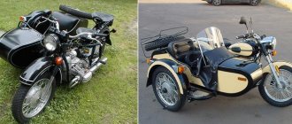
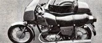
Models of IZH motorcycles are as unified as possible. The wiring diagram for IZ Jupiter 2 is not much different from later versions of the IZ motorcycle. There are external differences. For example, the Planet 5 bike has one cylinder, and the Jupiter 5 has two.
The first 12-volt motorcycle was the IZH Jupiter 4. The wiring diagram for the IZH Jupiter 5 and the wiring diagram for the IZH Jupiter 3 differ in components.
Wiring diagram IZ Jupiter 5
The bike of the fifth Jupiter has a contact SZ, which is powered by a battery, so the operation of the vehicle is highly dependent on the state of charge of the battery.
If charging is insufficient, the following problems occur:
- the motor runs intermittently;
- the engine starts with difficulty;
- At low speed the battery is discharged.
These problems can be eliminated by switching to BSZ. Any electrician can handle this task (the author of the video is Viter Electronic).
How to make the transition to contactless SZ?
To switch to contactless SZ, motorcyclists use parts from other motorcycle models. When upgrading the generator set, the wiring of the IZH Jupiter 5 remains unchanged. Minor alterations concern the electrical circuit of the IZH. After changes, the battery is used to service auxiliary equipment. To switch to BSZ, parts are taken from Planet 5 and the VAZ 2108 car.
The following changes are being made to the electrical circuit of IZH:
- install 2 Hall sensors from the eighth VAZ model;
- 2 VAZ electronic switches must be connected to the sensors;
- each of the cylinders serves a commutator-sensor pair;
- You need to add two more ignition coils to the circuit.
SZ after modernization
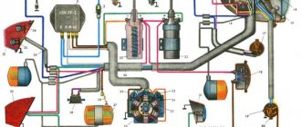
On the electrical circuit of the IZH motorcycle, the components are marked with numbers:
- Spark plug.
- Ignition coils from Planet 5.
- Switches.
- Hall sensors.
- Egnition lock.
- Battery.
For the created ignition system, it is necessary to modify the IZ Jupiter 5 generator, the circuit of which will not require major changes.
How can I modify the generator?
The presented modernization option is advantageous in that it does not require the purchase of a new generator that will service the new ignition system.
Recycled generator design
All you need to do is follow these steps:
- make a modulator-breaker of an electrical circuit;
- install a breaker on the rotor shaft or generator.
You can create a modulator with your own hands. To do this, you need to take a metal plate and drill a hole in it for the fastening bolt. The manufactured part will serve as a modulator-chopper.
Homemade modulator for interruption
The modulator is connected as follows:
- install the modulator plate (2) and tighten it with the bolt (3), but not all the way;
- by rotating the crankshaft, you need to ensure that the piston is at top dead center;
- Next you need to set the ignition timing;
- Now you can tighten the mounting bolt on the plate.
Hall sensors (1) are installed together with the modulator.
Communities › Around the Wheel (motorcycles, ATV, jet skis) › Blog › BSZ and R-R with a road bridge on IZH Yu-5
I have in my garage my “Old Friend” IZH Yu-5, which was given to me when I graduated from school! The only owner of which is only me. I haven’t driven it for a long time, more than 10 years, and it wouldn’t start, there was no charging, constant problems with the cams and dead ignition coils, and of course the right pot! It's time to revive your comrade! It was decided to install the BSZ, do normal charging with car elements and replace the wiring! I go to the store and buy parts: 1. Relay - regulator 2101, 2106. 2. Diode bridge of the generator (suitable for VAZ and GAZ generators. 3. Capacitor for diode bridges (in my opinion, they are all the same for VAZ and GAZ) 4. 2 spark plugs from GAZ with an electronic ignition system. 5. 2 short high-voltage silicone wires (I bought it for fifty dollars in some garage cop) 6. Ignition coil (VAZ 1111, GAZ with engine 406) two-terminal, dry. 7. Switch (VAZ 2108) 8. Hall sensor (VAZ 2108) 9. Connecting blocks for the switch and the Hall sensor 10. Emergency ignition (just in case) 11. Terminals, wires, electrical tape and nut - I think everyone has them in the garage 12. Ordered a modulator plate and a fastening plate The hall sensor on the internet was scrapped by myself))
Installing the BSZ 1. Remove the breaker contacts, coil, capacitor and all other crap from the contact ignition. 2. We put the switch in the right glove compartment, the coil under the tank. 3. Unscrew the generator bolt. 4. Install the modulator. 5.Attach the Hall sensor. 5.1. We fasten the modulator, but do not tighten it! 6.We connect everything according to the following scheme. Save to Album Diagram 1 Diagram 1
7. We put the armor wire on the spark plug and connect it to the coil. Everything is done according to the first scheme, everything is done in an elementary way and in terms of time you can do it in an hour with smoke breaks. 8. Connect the ignition coil. Save to Album 2 color scheme 2 color scheme
The ignition is set simply: the piston is at TDC further 3.5 mm back and for the convenience of finding the moment of the spark, an instant diagnostic unit “MD-1” was purchased
Next, we are engaged in charging 1. We throw out all the elements of the old charging system 2. Brushes. Since the relay-regulator used controls the current on the rotor through (+), you need to do the following. Plastic blocks are installed on the generator housing, which allow you to isolate the wire connections from the housing. We find the connection between the white brush wire and the short wire with the black wire and release the brush wire (unscrew the nut on M3). There is a 3mm terminal mounted on it, we drill it out to 4mm. And now we put this terminal on the mounting screws of the block itself and tighten it, thereby applying it to the brush (-). 3. Diode bridge. On the BPV, black wires (-) go to the lower left part of the BPV and red wires (+) to the middle lower part of the BPV. And three pink ones on the right side of the GSV. We release the black ones and twist them, and we do the same with the red ones. And we remove the pink ones (they come from the generator from each phase and supply alternating current from each phase, of which there are only three) and leave them as is. The diode bridge consists of two plates, one of them is (+), the other (-) and they are insulated from each other, the plate that has insulation on the mounting hole (at the end) is (+). We connect the red wires (+) to plate. And we connect the black and brown ones to ground (-). The diode bridge is connected. 4. Relay regulator. Take (+) anywhere after the ignition key. This terminal will go to the groove size No. 15. We take the wire (+) of the brush, it was removed from the lower right part of the BPV, this is the wire for terminal size No. 67. We take the solution and connect it. Next, we screw the solution to ground; you can’t start it without this, otherwise it will burn out! 5. To make sure the charging light on the dashboard goes out, run it through the relay.
Improving the standard system
The ignition system can be improved in other ways. To do this, you need to identify what problems there are with the wiring. They can occur in the primary circuit between the coil and the 12V battery or due to operating conditions. A visual inspection of the primary circuit can reveal problems with connections, contacts and the ignition switch.
If operating conditions are ideal, the primary circuit will operate with a 12V battery without failure.
But when dirt and dust get into the circuit, the resistance at the contact points increases, which entails a decrease in voltage from 12 Volts to 7-8 Volts. This voltage is not enough for a powerful discharge to appear in the secondary winding of the coil. As a result, a charge of less than 12 V appears on the spark plug, which poorly ignites the combustible mixture in the cylinders. Burnt contacts, oily spark plugs and batteries with a charge of less than 12 V further worsen sparking.
Standard wiring after modification
The following measures help solve these problems:
- The plug connectors are removed and each wire is soldered using traditional soldering and then insulated.
- An additional toggle switch is installed that turns off all consumers when the engine starts. Thus, the coils are supplied with 12 volt voltage from the battery (diagram 1).
- Remake the ignition switch (IZ) (diagram 2). You need to take a wire and solder one end of it to the connector of lock 4, which is free, and the other to the positive terminal of the coil. The standard wire should be re-soldered from terminal 5 to terminal 6. After turning on this position of the key, power is supplied from the battery to the primary circuit according to a simplified scheme.
Thus, the changes made will make the electrical wiring of the IZH Jupiter 5 motorcycle more reliable and efficient.
Diode bridge for Izh Jupiter 5 installation
Motorcycle IZH - Jupiter 5 One of the diseases of IZH is charging the battery.
It is treated quite easily and simply. To do this you will need:
— relay-regulator from VAZ 2106
— 6 connecting chips (female)
- basic knowledge of electrical engineering
And so let's start the installation.
We disconnect wire “X1” from the BVP and screw it to ground. We disconnect the positive wire from the generator brush and connect it to terminal “67” on the RR. We also connect the positive wire from the ignition switch or from terminal “X8” of the BVP to terminal “15” on the RR.
Next, we connect a 5-pin relay, it is needed so that the charging indicator lamp goes out. We connect the positive wire from “X8” to terminal “30”. Connect terminal “85” to ground. We disconnect terminal “X3” from the BVP and connect it to relay “88”. We run a wire from terminal “86” and connect it to terminal “X7”.
Features of electrical equipment
Despite the unification of parts with other models, the IZH Yu5 wiring diagram was chosen for battery use.
We are talking about a contact ignition system, which, if the battery is dead, immediately creates problems for the owner:
- Starting the engine is difficult;
- The engine runs intermittently;
- Driving at low speeds further drains the battery.
Therefore, many owners prefer to upgrade their ignition system with their own hands to a more progressive one - a contactless electronic type. It should also be noted that repairing the wiring of IZ Jupiter 5 should there be a desire for such an upgrade (see also the article about the wiring diagram of IZ Planet 5).
For reference: unlike the Jupiter model, new wiring and an electronic ignition system were installed on the modified IZ Planet 5.
The methods proposed below are designed for simplified work - not requiring major replacement of components.
Transition to a contactless ignition system
Over the years of operation, the owners of IZH Jupiter 5 have developed more than one instruction for altering the electrical network. And almost all of them are based on elements from other domestic motorcycles (see also the features of the Ural motorcycle wiring diagram).
But there is a more progressive way in which:
- The generator and wiring remain on IZ Jupiter 5;
- Minor modifications are made to the electrical circuit;
- The battery remains for servicing auxiliary systems.
We are talking about modernizing the ignition system with the combined use of elements from the VAZ-2108 car and the Planet 5 motorcycle.
At the same time, the wiring diagram for IZ Jupiter 5 remains the same:
- Two Hall sensors are installed;
- Two electronic switches are connected to them (items 1 and 2 - from VAZ). Each sensor-commutator pair covers 1 cylinder;
- Two ignition coils from a motorcycle of the IZh family.
In the diagram above, the numbers indicate:
- Spark plug;
- Reels Planet 5;
- G8 switches;
- Hall sensors from the "eight";
- Egnition lock;
- Accumulator battery.
Modification of the generator
This technology for switching to a contactless ignition system is interesting because the motorcycle owner does not need to buy a new generator designed to work in an electronic ignition system. Accordingly, the cost of rework will be minimal.
- Make a modulator that will interrupt the circuit;
- And install it on the generator (on the rotor shaft).
A metal plate with a hole drilled in it for a mounting bolt can serve as such a modulator-chopper.
The modulator installation procedure is as follows:
- The modulator plate (in the diagram below under No. 2) is installed under the mounting bolt;
- Slightly attracted to him;
- By rotating the crankshaft, set the piston to TDC;
- We set the ignition timing;
- Tighten the plate with the mounting bolt.
For reference: in addition to the modulator, two Hall sensors are installed under the engine cover (in diagram No. 1). There are places to attach them.
Wiring diagram IZ Jupiter 5: alterations of the ignition system
Did you like the article? Follow our channel for new ideas of useful car tips. Subscribe to us in Yandex.Zen. Subscribe.
The main visual difference between the two motorcycles of the IZh family is the number of engine cylinders. The Jupiter 5 model has two of them, while the Planet 5 has only one.
In all other respects, the models are maximally unified with each other, with the exception of electrical components.
For reference: another design feature of the IZ Jupiter of the last 5 years of production is the use of water cooling. And Planet 5 has all air-cooled engines.
Improving the standard system
For those owners who do not want to switch to a contactless ignition system, there are other ways to improve sparking.
At the same time, the wiring of the IZH Jupiter 5 motorcycle is analyzed for problem areas, and most often:
- The primary circuit from the battery to the coil is diagnosed;
- Locations of voltage reduction caused by operating conditions are identified.
A simple inspection of the primary circuit will demonstrate several problem areas at once:
- four plug connectors;
- emergency ignition switch;
- central switch contacts;
- breaker contacts.
Under ideal operating conditions, such a complex section of the chain will work flawlessly.
But in practice, it is exposed to dust and dirt flying from under the wheels, so in the circuit due to the increase in resistance at the contact points:
- the voltage decreases from 12 V to 7-8 V;
- this is not enough to excite a powerful discharge in the secondary winding of the coil;
- as a result, a low discharge on the spark plug, making it difficult to ignite the combustible mixture in the cylinders.
And if you add to this a dead battery and oily spark plugs with burnt contacts, then the sparking process becomes completely problematic.
Motorcyclists solve such defects as follows:
- traditional soldering. The wiring on IZH Yu5 gets rid of plug connections and each wiring is soldered manually, followed by insulation;
- installation of an additional toggle switch (in diagram No. 1), which turns off all consumers at the moment the engine starts. This allows the maximum voltage from the battery to be supplied to the coil;
- alteration of the ignition switch.
A wire is soldered to the free connector of lock 4 (in diagram No. 2), the second end of which is fed to the positive terminal of the coil. The standard ignition wire from terminal 5 is transferred to terminal 6 and when this key position is activated, a simplified power supply circuit from the battery to the primary circuit of the coil is activated.
Conclusions: from this article you can learn not only tried and tested methods for improving the electrical part of a motorcycle (as in the article about the electrical wiring of the Java 350), but also watch video materials that clearly demonstrate the algorithm for modernization work.
Source
If there is no charging on the Izh Jupiter motorcycle.
This article was written to help those motorists who decided to find and fix a malfunction in the battery charging system on IZH 12V motorcycles themselves.
Of the special instruments, you will need the simplest tester with a continuity function (tweeter) and resistance measurement. If you do not have this device, then you can use a light bulb with a battery to determine the contact or break in the circuit.
In this case, you need to install a well-charged battery on the motorcycle, or power the on-board network from another external power source with a constant voltage of 12 V. First of all, we check the presence of voltage with the ignition switch on at the positive terminal of the regulator relay. There should be +12v.
If there is no voltage, then we look for a break from the positive terminal of the battery through the ignition switch and to the + terminal on the relay regulator.
Next, we measure the voltage on the brushes. There should be +12V on one of the brushes. If not, we call the wiring from the relay to the generator brushes.
Next step. We take the brushes out of the holder and ring each of them from the terminal to the graphite. It happens that at the point of contact of the wire with the graphite body of the brush itself, the contact is lost.
Troubleshooting the generator
Three phase wires are disconnected from the stator and the winding (connected to each other according to a star circuit) is connected. That is, the windings should ring with each other and have approximately the same resistance. If some winding does not ring, this means that there is a break and the stator is not working properly.
Next, all three phases are called relative to the body (mass). If it rings, it means the windings are broken into the housing and the stator is not working properly.
Anchor
We ring the armature winding (on copper rings). If the rings ring among themselves - good, if not - there is a break, the armature is not working.
The next step is to wire the armature winding relative to the armature body.
If it doesn’t ring, it’s good; if it rings, the winding is broken into the housing and the armature is not working properly!
Relay regulator
If all the wiring is in order, the brushes, stator and rotor are ringing and everything is working, all that remains is the relay regulator! In my experience, even if you don’t have much knowledge of radio electronics, you can at least remove the back cover of the relay regulator and wipe off all the dirt. Carefully look at all the contacts, fastening parts, wires, jumpers; sometimes the contact or soldering simply falls off due to vibration. The diode bridge is practically “eternal”. But the control thyristors sometimes fly out! They are also called simply - to check for breakdown on the housing and between the cathode and the control electrode!
They are also easy to change; a 10 mm nut is unscrewed from below and the wires are unsoldered from above.
That's basically it. And there is absolutely no need to change entire components at random; there can be a lot of reasons, even banal bad contact on the chips or oxidation of the wires in the connector
The editors of the magazine thank Sergei Sharikov for kindly providing materials for the article.
If you have something to share with readers and would like to publish your story or photo report about your travels on our website, please send the materials to:
Source
Content:
There is no need to have special stands and equipment for repairs. A minimum knowledge of electrical engineering and a simple avometer (tester) is enough; even often you can get by with just a test lamp.
We will tell you in more detail about the main electrical wiring components and possible malfunctions. Finding a broken wire or damaged insulation is easy (for example, a bad contact always gets hot).
But pay special attention to the fact that the electrical circuit is designed not only for 12 volts, there is also a high-voltage cable (connecting the coil and the spark plug), which cannot be checked with a regular ohmmeter.
In this case, we look to see if there is a spark at the coil output and at the output at the spark plug contact. Now in detail about the main wiring components of the Izh Planet.
Generator
The heart is the generator (sometimes called a magneto, but they were never used on Izh Planet). Three windings produce alternating current. For excitation, an additional coil is used instead of a permanent magnet. Therefore, it is impossible to jump start a motorcycle with a completely dead or missing battery.
A diode bridge for current rectification and a voltage regulator assembled in one unit are mounted on the Izh Planet 5 generator (they are not even highlighted in the Izh Planet wiring diagram manuals).
Possible breakdowns in this unit:
- It is checked by measuring their resistance of current-carrying conductors and insulation. If the generator is damaged, it will become noticeably hot.
- — the output voltage will differ significantly from the nominal level or be absent.
- Although the electrical circuit includes short circuit protection, it happens that the automation does not work and most often the output transistor burns out.
How to install BSZ (contactless ignition), diode bridge and relay regulator on a motorcycle
I have been repeatedly asked to share my experience in installing a BSZ, a diode bridge and a relay regulator. I did this as much as possible, until they began to insist that I break out in an article where I could explain everything in an accessible way. The whole difficulty lies in the fact that after these installations I long ago moved towards reworking the Izh-Yunker electrical circuit. And today, reproducing exactly how it actually was on a motorcycle is quite problematic, and even more so since the wire connection points and their colors on any electrical circuits differ from the factory ones, including the fact that I encountered the fact that on different motorcycles (Izh - Juncker) the same wires are different in color.. Therefore, I will not tell you the specific color of the wire and tie it to the diagram, but I will name the wires according to their functionality, for example: “this wire goes to the left rear marker,” and you you will have to recognize it in practice, which, by the way, is very useful for experience. I won’t describe the advantages of this or that device or the advantages of this or that method, everyone chooses shoes according to their feet, I’ll just try to present them in a way that is simple and understandable. So let's begin.
Battery
The battery in the motorcycle is low-power. The motorcycle does not have a starter, so its task is only to supply voltage to the ignition system and the generator excitation winding during starting. Thanks to the battery, designed for 12 volts, a stable start of the fifth Planet is ensured; up to the third model, the wiring was 6 volt, and the ignition was not always clear.
Possible battery malfunctions:
- - housings, plates, leakage of electrolyte.
- - determined by measurements using a hydrometer.
- - detected by measuring resistance.
- minus not on the body (frame) of the motorcycle - all the electronics will not work.
Electrical equipment IZH Planet 5
Wiring for IZH Planet 5 includes:
- generator;
- battery;
- ignition system;
- headlights;
- control devices;
- switching elements.
Video: review of IZH Planet 5 wiring
Taken by user Agronom.
Generator
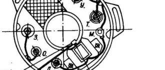
IZ Planet 5 generator design:
- voltage regulator with rectifier BPV-14-10 - 1;
- rotor - 2;
- stator with windings - 3;
- current collector brushes - 4;
- ignition system cam (battery) - 5;
- ignition system contact unit - 6.
The generator converts the mechanical energy of a gasoline engine into electrical energy, which charges the battery. Alternating current is generated by 3 windings and fed to a rectifier, which converts it into direct current. An additional coil is used as an exciter.
Photo gallery: IZH Planet 5 generator and its design
Generator IZH Planet 5
Generator device
Battery
To supply all components, a low-power energy storage device of 12 volts is required, since IZH Planet 5 does not have a starter. The purpose of a lead-acid battery is only to supply voltage to the ignition system and the excitation winding of the generator during startup.
Battery
Ignition system
In IZH Planet 5, the ignition coil converts low-voltage voltage into high-voltage and transmits it to the spark plug. That, in turn, is responsible for the spark that detonates the fuel. To ensure that detonation occurs only in the desired piston position, there is an ignition chopper.
Ignition system
From the factory, this model is equipped with a classic ignition system, which requires periodic cleaning of the breaker contacts and adjusting the gap between them.
Installing a contactless SG on a motorcycle gives:
- timely powerful sparking;
- reduction of vibration levels;
- reduction in fuel consumption.
Control devices
The following control devices are installed on the motorcycle:
- tachometer, on which there are indicator lights for the headlights and turns;
- speedometer showing total and daily mileage;
- power engine temperature indicator;
- voltmeter.
Control devices
Headlight and dashboard lamps
Conventional incandescent lamps are installed as lighting equipment and to illuminate the dashboard. Switching elements are responsible for supplying electricity from the battery to the lamps.
The headlight circuit includes lamps:
- headlight (35 watt);
- parking light headlights (4 W);
- control - blue light (2 watts);
- rear brake light (15 W).
Headlight
Switching elements
Switching elements are various types of switches that close or open an electrical circuit. They can be activated using keys on the dashboard (for example, turn signals) or by sensors.
In IZH Planet 5, the switching elements include:
- turn switches;
- signal key;
- switches for low/high beam headlights;
- neutral sensor;
- egnition lock;
- foot and hand brake sensors.
Ignition system
The ignition chopper is used to ignite a spark at a certain point in the piston stroke. In early modifications of the electrical wiring of Izh Planet 5, contact was mounted, later electronic.
The main malfunctions of this unit:
- Burning of breaker contacts is determined visually.
- Failure of a sensor or switch elements - the easiest way to detect it is to use the method of installing a known-good unit. The lubrication system sensor valve is also checked using the same method.
- An incorrectly set ignition timing is visible from the fuzzy operation of the engine. It can be eliminated by adjustment using special probes.
The ignition coil increases the voltage to several kilovolts so that the discharge can ignite a spark at the spark plug electrodes. The secondary winding is made of a fairly thin wire; most often it burns out. Although a breakdown between the turns or onto the housing is also possible. The same troubles can (but less often) happen to the primary circuit. Everything is revealed using resistance measurements.
Wiring diagram Izh planet - 5, how to determine the malfunction
07.04.2017
While easily fixing mechanical failures, motorcyclists experience difficulties if the electrics fail. It’s completely in vain, the wiring diagram of the planet Izh 5 is not complicated, it’s easy to figure out.
There is no need to have special stands and equipment for repairs. A minimum knowledge of electrical engineering and a simple avometer (tester) is enough; even often you can get by with just a test lamp.
We will tell you in more detail about the main electrical wiring components and possible malfunctions. Finding a broken wire or damaged insulation is easy (for example, a bad contact always gets hot).
In this case, we look to see if there is a spark at the coil output and at the output at the spark plug contact. Now in detail about the main wiring components of the Izh Planet.
Generator
The heart is the generator (sometimes called a magneto, but they were never used on Izh Planet). Three windings produce alternating current. For excitation, an additional coil is used instead of a permanent magnet. Therefore, it is impossible to jump start a motorcycle with a completely dead or missing battery.
Possible breakdowns in this unit:
- Breakdown or breakage of coils. It is checked by measuring their resistance of current-carrying conductors and insulation. If the generator is damaged, it will become noticeably hot.
- Failure of the diode bridge - the output voltage will differ significantly from the nominal level or be absent.
- Failure of the voltage regulator. Although the electrical circuit includes short circuit protection, it happens that the automation does not work and most often the output transistor burns out.
Battery
The battery in the motorcycle is low-power. The motorcycle does not have a starter, so its task is only to supply voltage to the ignition system and the generator excitation winding during starting. Thanks to the battery, designed for 12 volts, a stable start of the fifth Planet is ensured; up to the third model, the wiring was 6 volt, and the ignition was not always clear.
Possible battery malfunctions:
- Mechanical damage - housing, plates, leakage of electrolyte.
- Loss of electrolyte density is determined by measurements using a hydrometer.
- The short circuit of the plates in the banks is detected by measuring the resistance.
- It is possible that the connection is not correct, minus not on the body (frame) of the motorcycle - all the electronics will not work.
Ignition system
The ignition chopper is used to ignite a spark at a certain point in the piston stroke. In early modifications of the electrical wiring of Izh Planet 5, contact was mounted, later electronic.
The main malfunctions of this unit:
- Burning of breaker contacts is determined visually.
- Failure of a sensor or switch elements - the easiest way to detect it is to use the method of installing a known-good unit. The lubrication system sensor valve is also checked using the same method.
- An incorrectly set ignition timing is visible from the fuzzy operation of the engine. It can be eliminated by adjustment using special probes.
- The ignition coil increases the voltage to several kilovolts so that the discharge can ignite a spark at the spark plug electrodes. The secondary winding is made of a fairly thin wire; most often it burns out. Although a breakdown between the turns or onto the housing is also possible. The same troubles can (but less often) happen to the primary circuit. Everything is revealed using resistance measurements.
Headlight and alarm lamps
Regular incandescent lamps are used; it is not difficult to find a burnt coil.
Switching elements
These include switches (high-low, turns, engine stop, etc.) as well as brake and neutral sensors and the ignition switch. You can easily “ring” them with a tester, finding out which contact group is not working.
As can be seen from all of the above, the wiring on Izh Planet is without any special secrets or complex elements, all its parts are easily diagnosed and repairs should not cause difficulties.
Now we advise you to watch the video, which shows in detail and clearly the assembly of the Izh Planet 5 circuit.
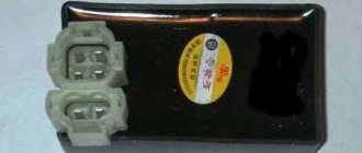
The charger disappeared somewhere and suddenly reappeared, it suddenly stalled during the journey or some mode does not work and the tidy is acting up - a common problem that needs to be solved. After many years of use, when you start to figure out what goes where and where, the roof goes askew, there are some twists, kilometers of electrical tape, oh yeah, things won’t work that way! I’ll say right away that I work at a car disassembly shop, getting wires or spare parts is not a problem, so, it’s decided and done - the wiring is made of Japanese wires and Chinese heat shrink. I spent a day on this. I didn’t buy connectors, I just opened them, took the wire of the required length, inserted it, clamped it, sealed it, put on a heat-shrink tube - hair dryer and voila! The wiring is ready, then the whole harness is braided, we look and rejoice. I decided to put up a horseshoe because I wanted to and that’s it! Is there too much room under the saddle for me? For supertuning, we will need a horseshoe from a vase (about 270 rubles), a relay-regulator (about 150 rubles), it’s better to buy it in a good store, make two brackets ourselves [-shaped (not visible in the photo, the relay is attached to them), an angle grinder. We “finalize” the relay regulator - we cut off a little meat (in the picture on the top left where the output contact is), we bend the contact itself inward, we also make two mounting holes, you can dig it out by hand with a 3 mm drill Using a grinder, we cut off the excess on the generator so that the diode bridge is without problems got in there. Everything is done locally and to the best of your imagination (we file the diode bridge so that the clutch cover does not touch it!). We secure the horseshoe with bolts - so that the diodes do not touch the ground, I used textolite washers. Yes, it’s not very beautiful, but it’s compact and has been working for the second season! Don’t forget, aluminum doesn’t solder well, so it’s better to make a hole, screw on a small bolt and nut and solder the positive wire to it!
in this picture everything is chewed in detail
BSZ! every homeowner's dream! I won’t describe the entire process of purchasing and components; there is plenty of information on the Internet. Like everyone else, I first decided to install a hall sensor (HH), I drove it for a ride, it works, but progress does not stand still! I found a replacement - the BS5-2M optical sensor! It costs quite a lot - about 250 rubles. The VAZ switch receives its signal without any problems. beautiful, but expensive, and if an arctic fox fails somewhere, it’s better to carry a spare one with you (if you still install BS5, I advise you to solder the body and side of the contacts carefully with a soldering iron, otherwise it may die from vibration) And finally, a few photos
Switching elements.
These include switches (high-low, turns, engine stop, etc.) as well as brake and neutral sensors and the ignition switch. You can easily “ring” them with a tester, finding out which contact group is not working.
Switching also includes the Izh electronic turn signal relay. Its malfunction is visible by the absence of interruption or no voltage supply to the turn signals.
As can be seen from all of the above, the wiring on Izh Planet is without any special secrets or complex elements, all its parts are easily diagnosed and repairs should not cause difficulties.
Now we advise you to watch the video, which shows in detail and clearly the assembly of the Izh Planet 5 circuit.
Checking the serviceability of the generator can be done on a motorcycle without disassembling the generator.
To carry out the work you will need a multimeter.
1. Place the motorcycle on the center stand or side stand.
2. Disconnect the battery by removing its fuse.
3. Remove the right cover of the power unit.
4. 6mm wrench
unscrew the nuts securing the five “upper” wires of the generator. In order not to confuse the wires during subsequent assembly, we mark them or tie them with thin wire so that we get a cable.
Maintenance
The owner can independently perform some maintenance procedures:
set the gap between the breaker contacts;
The need to inspect and adjust the wiring arises if:
- the motorcycle moves in the rain for a long time, as this causes oxidation of the contacts;
- a motorcyclist rides in an area with a lot of vegetation that damages wiring;
- The driver rides in snow in winter, which can stick to electrical wiring parts and damage them.
Self-check of the Planet 5 motorcycle generator in case of loss of charge
The cause of loss of charge in the IZH Planet 5 battery is most often a breakdown of the generator.
To check it yourself you need:
- multimeter device;
- straight screwdriver.
Step-by-step instruction
The following steps must be followed:
- Disconnect the wires from the battery and remove the generator cover.
- Disconnect the top 5 wires from the generator, first unscrewing their fastenings. In order not to mix up the wires during assembly, it is worth marking them.
- Measure the winding resistance using a multimeter in ohmmeter mode. To do this, you need to touch the body with one probe, and the other should be connected in turn to the 3 wires of the winding. There should be no short circuits, as indicated by the inscription on the multimeter screen.
- Test the resistance between the stator contacts: you need to touch them one by one with the multimeter probes. The value on the screen should be 8 ohms.
The presence of a short circuit in the 3rd stage or a discrepancy in the indicators in the 4th will indicate problems with the generator.
Photo gallery: stages of checking the IZH Planet 5 generator in case of loss of charge in pictures
How to correctly set the gap between the contacts of the breaker?
In order to set the gap between the breaker contacts, you will need:
- straight screwdriver;
- wrench 10;
- candle key;
- probe thickness 0.4 mm (+/- 0.05 mm).
Next, you need to follow the steps sequentially:
- Place the motorcycle on a stand and place the gearbox in neutral.
- Remove the right crankcase cover and unscrew the spark plug.
- Using a 10mm wrench, grab the generator rotor mounting bolt and turn the crankshaft to a position where the contacts are as far apart as possible.
- Loosen the screw securing the contact.
- Place the probe between the contacts and adjust the tightening of the eccentric screw until the probe passes the contacts with little resistance.
- Tighten the contact fixing screw.
Photo gallery: adjusting the gap between the breaker contacts
Troubleshooting the audio signal and improving signal quality
Poor sound signal quality is mainly caused by improper adjustment.
The following tools will be needed for setup:
- wrench 7;
- a simple screwdriver.
Step-by-step instruction
To adjust, do the following:
- Loosen the locknut with a wrench.
- Turn on the ignition.
- Press the button to turn on the sound signal.
- Adjust the sound by rotating the adjusting screw.
- When the desired result is achieved, tighten the locknut.
Photo gallery: sound signal of IZH Planet 5 and its settings
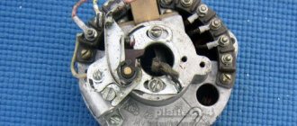
Generator stator 281.3701 for IZH motorcycles
The stator is installed on the right half of the engine crankcase and secured with three bolts. The frame is made of special sheet steel. It has 18 tooth-shaped places for winding phase windings. The phase winding is made of one solid wire with a diameter of 0.9 mm and is wound on six teeth. Each tooth has 20 turns of copper wire wound around it. There are six teeth in total on the winding, so 120 turns are wound. There are three such windings. The connection of the windings is made with a star. The terminals of the phase windings are connected to the terminals of the comb.
The generator stator is covered with an aluminum alloy cover. There are special places on the cover and threaded holes where the carbon brush holder is installed. A breaker with a capacitor to produce a spark. Special comb for connecting wires.
Izh Yu 3 does not work without battery
If there is no charging (6 volts).
Since questions about the lack of charging on 6-volt motorcycles have become more frequent on the forum, I offer a simple guide to action in such cases. First of all, by external inspection, make sure that all the wires are securely fastened, the tips are not oxidized, the battery is charged, and the indicator lamp for the generator is working properly. It would be useful to open the cover of the relay regulator and check the condition of the contacts. Have a diagram of your motorcycle. Let's get started.a) When the engine is not running and the ignition is on, the indicator lamp on the headlight lights up with a low glow. Check the battery charge level. Check the reliability of the connection of the electrical wire contacts in the battery - central switch circuit, as well as the condition of the central switch contacts, the warning lamp holder and the battery terminals for oxidation. Remember: have you recently tightened any long screws or self-tapping screws in the generator area that could cause a short circuit? b) The control lamp lights up at all engine speeds with an even glow. First of all, check the operation of the generator, for which connect the “W” terminal of the generator to “ground” and connect the lamp to the “I” and “W” terminals for 6 volts. If, while the engine is running (do not over-gas the lamp, it won’t take long to burn out) the lamp does not light up or burns with a low glow, then the generator is faulty, and in this case it is necessary to check: 1. Ease of movement of the brushes in the brush holder. In case of jamming, clean the brush holder. (Brushes are a special topic: if you have changed them, check them with an Avometer/multimeter; their resistance should be about 1 ohm; now brushes with a high carbon content and a low graphite content are on sale, their resistance is 20-30 ohms - they are not suitable , definitely throw it away. We try with a drill, a VAZ-classic - grind it first.) 2. The presence of contact between the brush and the current-carrying wire - external inspection. If necessary, replace the brush. 3. Presence of contact between the brushes and the commutator, no hanging of the brush in the brush holder on the wire - external inspection; if there is no contact due to excessive wear, replace the brush. (A brush is considered worn out when worn by 1/4 of the length, i.e. up to a size of 11 mm .) do not forget that the brush connected to the “I” terminal is isolated from ground. 4. Condition of the surface of the collector - external inspection; if the surface of the lamellas is dirty or oily, wash the collector with gasoline or clean it with glass sandpaper. (I insist with glass sandpaper)
5. Check the serviceability of the generator stator excitation coils with an avometer/multimeter. If there is no avometer, disconnect the wires coming from the bundle from the terminals “M”, “I”, “W” of the generator, without removing the output wires of the excitation coils from the terminals “I” and “W”. Disconnect the output wire of the excitation coils (an additional resistance that is available on motorcycles with an IZH-56 relay-regulator) from ground. Then connect one terminal of the battery to the generator terminal “I” or “W”. Connect any motorcycle lamp in series to the second terminal of the battery, and the second contact of the lamp to the free terminal “I” or “W”. If the lamp does not light, it means that there is a break in the excitation coils (usually due to the lack of contacts at the junction of the excitation coils). It is necessary to check the connections of the coils and, if necessary, solder them. If there is no break in the field windings, i.e. the lamp is on, then it is necessary to additionally check that the field windings are not shorted to ground. To do this, connect one terminal of the battery to the “ground” of the generator, and the second - through the lamp to the “I” or “W” terminal. If the lamp does not light, then there are no short circuits and the generator stator is working. If the lamp is on, then you should find the location of the short circuit. To do this, remove the stator from the engine and re-check the absence of a short to ground of the stator coils using the above method. If the short circuit is eliminated after removing the stator, it means that it was caused by contact of the generator mounting screws with the excitation coil due to insulation failure or contact of the screws with the excitation coil wires at the connection points. If the lamp lights up when the stator is removed, the field coil is closed by contact with the pole. To determine the location of the damage, alternately disconnecting the excitation coils from each other, check each for the absence of a short circuit to ground using the method indicated above. Remove the damaged coil by unscrewing the screws securing the pole, apply insulation to the damaged area, securely fasten the coil with pole to the stator. It should be borne in mind that if the pole fastening screws are not tightened sufficiently, it may touch the anchor. If the stator is working and the generator is not working, then the armature is faulty. The anchor needs to be replaced and it is difficult to rewind. C) The generator is in good working order, but the control lamp lights up with an even glow at all engine speeds (that is, checking under point b) showed that the lamp is on - the generator is excited). Check the operation of the relay regulator. First, with the engine running, check whether the contacts of the reverse current relay are closing. If there is a short circuit of the contacts, i.e. the armature is pulled up, then it is necessary to turn off the engine, turn off the ignition and clean the contacts of the reverse current relay with a safety razor blade. It is unacceptable to clean the silver contacts of the relay with emery cloth or glass sandpaper, since in this case the abrasive cuts into the metal and breaks the electrical contact. If the relay contacts do not close and the armature is attracted, then you should check the adjustment of the gaps and the operating torque. In the case when the armature does not pull up and the contacts do not close, check the adjustment of the regulator, since at low voltage the reverse current relay may not operate.
D) The warning light goes out only at high engine speeds. The reason is the low voltage maintained by the relay regulator. Check and adjust the voltage regulator. D) When the engine speed increases and the lights are on, the lamps burn hot or burn out due to the high voltage maintained by the relay regulator. Check and adjust the voltage regulator. E) The control lamp burns with incandescence as the engine speed increases. The battery is connected incorrectly (reverse polarity of the battery terminals) or the generator is reversed polarity. Check and, if necessary, correctly connect the battery to the electrical circuit. If the battery is connected to the electrical circuit correctly, then the generator has been reversed. To reverse the polarity of the generator, it is necessary to open the relay-regulator and, with the ignition on but the engine not running, briefly close the contact of the reverse current relay.
If you can’t purchase a generator, you can rewind it (but then it’s better to think about installing 12 volt equipment) Armature winding PELBO or PEV-2-0.8 mm Number of turns in the section 9 Number of turns in the groove 18 Turn pitch along the groove from 1 to 6 Step turns along the collector ... from 1 to 11 Number of slots in the armature package ... 31 Excitation winding PEL-0.9 MM Number of turns in the coil. . 126 Number of coils 6 Resistance winding PEVMM-0.5 mm Resistance 6-7 ohm Wire length 2700-3000 mm Number of rows 2 Number of turns in each row 8-9
a resistance winding is only needed if you have PP-IZH-56; with PP-1 it is not required. I wish you good luck! when writing, materials from the book “Advice to the driver of an IZH motorcycle” by V.A. Abrahamyan and V.A. Zabelin were used. There is also this addition: the G-36 generators are self-excited due to the residual magnetization of the stator. If you are installing a stator that has been idle for a long time, and even if it is surrounded by pieces of iron, it would not be a bad idea to magnetize it. Either we close the reverse current relay, or briefly apply + to the “I” terminal of the generator, while raising one brush
Generator rotor 281.3701
The generator rotor 1 is located inside the stator. It is installed on the crankshaft using bolt 3 and key 5. An excitation winding 6 is wound on the rotor core with a copper wire with a diameter of 0.56 mm, 600 turns are made. The winding resistance is approximately 6.4 ohms. For contact with the winding, two copper rings 2 and carbon brushes are used. They perform the work of a current collector.
How to remove the generator rotor 281.3701
The breaker cam 4 is installed in one position on the rotor shaft in a special socket and secured with a mounting bolt 3. Under this cam there is a thread that is intended for removing the rotor from the crankshaft. To remove the rotor, you need to screw the screw from the chain disassembly device into the thread. The device is located in the motorcycle tool. If there is no screw, you can use a regular bolt with an M10 thread. The only condition for the thread must be at least 70 mm. Turn until the screw rests on the crankshaft. Then we apply more force to tighten it, and the rotor is removed from the shaft.