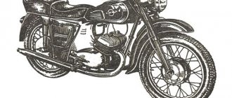
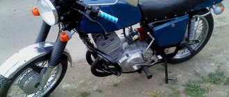
I have in my garage my “Old Friend” IZH Yu-5, which was given to me when I graduated from school! The only owner of which is only me. I haven’t driven it for a long time, more than 10 years, and it wouldn’t start, there was no charging, constant problems with the cams and dead ignition coils, and of course the right pot! It's time to revive your comrade! It was decided to install the BSZ, do normal charging with car elements and replace the wiring! I go to the store and buy parts:
1. Relay - regulator 2101, 2106. 2. Generator diode bridge (suitable for VAZ and GAZ generators. 3. Capacitor for diode bridges (in my opinion, they are all the same for VAZ and GAZ) 4. 2 spark plugs from GAZ with an electronic ignition system. 5 . 2 short high-voltage silicone wires (I bought it for fifty dollars in some garage cop) 6. Ignition coil (VAZ 1111, GAZ with engine 406) two-terminal, dry 7. Switch (VAZ 2108) 8. Hall sensor (VAZ 2108) 9. Connecting blocks for the switch and the Hall sensor 10. Emergency ignition (just in case) 11. Terminals, wires, electrical tape and nut - I think everyone has them in the garage 12. I ordered a modulator plate and a hall sensor mounting plate on the Internet to sharpen myself it was a mess))
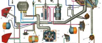
Installing the BSZ 1. Remove the breaker contacts, coil, capacitor and all other crap from the contact ignition. 2. We put the switch in the right glove compartment, the coil under the tank. 3. Unscrew the generator bolt. 4. Install the modulator. 5.Attach the Hall sensor. 5.1. We fasten the modulator, but do not tighten it! 6.We connect everything according to the following scheme. Save to Album Diagram 1 Diagram 1
7. We put the armor wire on the spark plug and connect it to the coil. Everything is done according to the first scheme, everything is done in an elementary way and in terms of time you can do it in an hour with smoke breaks. 8. Connect the ignition coil. Save to Album 2 color scheme 2 color scheme
Changes made by owners
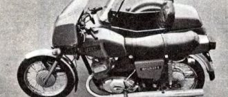
The unreliability of individual components and faulty wiring on IZ Jupiter 3 forced the owners to delve into all the intricacies of the modernized elements.
And the first to cause numerous complaints were changes in the primary circuit of power supplies:
- Battery;
- Generator.
As well as ignition systems and circuits for lighting devices of the trailer module - a cargo-passenger stroller. In most cases, the reason for the refusal was a banal manufacturing defect.
Battery charging system
Given the total shortage of spare parts for motorcycles that existed in those years, unplanned failure:
- battery;
- voltage regulator relay;
- ignition coils;
left the owners without transport for a long time. In addition, poor-quality assembly of individual elements led to unstable operation of all systems. This forced me to improve and polish the factory defects with my own hands (for example, see how to modernize the wiring diagram of IZH Planet 5).
Tip: the regulator circuit presented above has been tested on many motorcycles of the IZh family. Its peculiarity lies in the separate power supply - when turned on, the ignition circuit receives “+” from the battery. And the excitation windings are powered from the generator (terminal “I”) and do not discharge the battery when the engine is stopped.
Generator replacement
The operation of the standard G36M7 DC generator also caused a lot of comments. Frequent breakdowns and unstable operation forced the owners to look for a replacement.
The new modifications of the IZh family with 12-volt generators that appeared immediately attracted the attention of the owners of the IZH Jupiter 3, who were able to find a way to convert their motorcycle to a new operating scheme (see also the IZH Jupiter 5 wiring diagram).
If there is no charging on the Izh Jupiter motorcycle.
This article was written to help those motorists who decided to find and fix a malfunction in the battery charging system on IZH 12V motorcycles themselves.
Of the special instruments, you will need the simplest tester with a continuity function (tweeter) and resistance measurement. If you do not have this device, then you can use a light bulb with a battery to determine the contact or break in the circuit.
In this case, you need to install a well-charged battery on the motorcycle, or power the on-board network from another external power source with a constant voltage of 12 V. First of all, we check the presence of voltage with the ignition switch on at the positive terminal of the regulator relay. There should be +12v.
If there is no voltage, then we look for a break from the positive terminal of the battery through the ignition switch and to the + terminal on the relay regulator.
Next, we measure the voltage on the brushes. There should be +12V on one of the brushes. If not, we call the wiring from the relay to the generator brushes.
Next step. We take the brushes out of the holder and ring each of them from the terminal to the graphite. It happens that at the point of contact of the wire with the graphite body of the brush itself, the contact is lost.
Troubleshooting the generator
Stator
Three phase wires are disconnected from the stator and the winding (connected to each other according to a star circuit) is connected. That is, the windings should ring with each other and have approximately the same resistance. If some winding does not ring, this means that there is a break and the stator is not working properly.
Next, all three phases are called relative to the body (mass). If it rings, it means the windings are broken into the housing and the stator is not working properly.
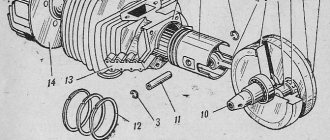
Anchor
We ring the armature winding (on copper rings). If the rings ring among themselves - good, if not - there is a break, the armature is not working.
The next step is to wire the armature winding relative to the armature body.
If it doesn’t ring, it’s good; if it rings, the winding is broken into the housing and the armature is not working properly!
That's it with the generator.
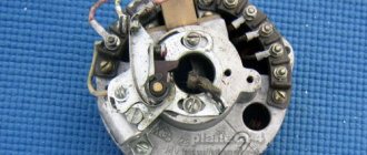
Relay regulator
If all the wiring is in order, the brushes, stator and rotor are ringing and everything is working, all that remains is the relay regulator! In my experience, even if you don’t have much knowledge of radio electronics, you can at least remove the back cover of the relay regulator and wipe off all the dirt. Carefully look at all the contacts, fastening parts, wires, jumpers; sometimes the contact or soldering simply falls off due to vibration. The diode bridge is practically “eternal”. But the control thyristors sometimes fly out! They are also called simply - to check for breakdown on the housing and between the cathode and the control electrode!
They are also easy to change; a 10 mm nut is unscrewed from below and the wires are unsoldered from above.
That's basically it!!! And there is absolutely no need to change entire components at random; there can be a lot of reasons, even banal bad contact on the chips or oxidation of the wires in the connector
Sergey Sharikov
The editors of the magazine thank Sergei Sharikov for kindly providing materials for the article.
If you have something to share with readers and would like to publish your story or photo report about your travels on our website, please send the materials to:
This might be interesting
- Tuning the Izh motorcycle. BSZ on Izh Jupiter The main “soreness” of the Izh Jupiter motorcycle engine is the standard contact ignition system. Any owner of Jupiter...
- On bicycles through the mountains This is a report on a journey by bicycles through the Caucasus Mountains of completely unprepared people. Read this article and you...
- Car loan. Article 5. Reviews about car loans It’s up to you to decide whether to take out a car loan or not. We publish reviews from consumers and car owners who at one time...
Maintenance
The owner can independently perform some maintenance procedures:
- check the motorcycle generator if the battery loses charge;
- set the gap between the breaker contacts;
- adjust the quality of the sound signal.
The need to inspect and adjust the wiring arises if:
- the motorcycle moves in the rain for a long time, as this causes oxidation of the contacts;
- a motorcyclist rides in an area with a lot of vegetation that damages wiring;
- The driver rides in snow in winter, which can stick to electrical wiring parts and damage them.
Self-check of the Planet 5 motorcycle generator in case of loss of charge
The cause of loss of charge in the IZH Planet 5 battery is most often a breakdown of the generator.
To check it yourself you need:
- multimeter device;
- straight screwdriver.
Step-by-step instruction
The following steps must be followed:
- Disconnect the wires from the battery and remove the generator cover.
- Disconnect the top 5 wires from the generator, first unscrewing their fastenings. In order not to mix up the wires during assembly, it is worth marking them.
- Measure the winding resistance using a multimeter in ohmmeter mode. To do this, you need to touch the body with one probe, and the other should be connected in turn to the 3 wires of the winding. There should be no short circuits, as indicated by the inscription on the multimeter screen.
- Test the resistance between the stator contacts: you need to touch them one by one with the multimeter probes. The value on the screen should be 8 ohms.
The presence of a short circuit in the 3rd stage or a discrepancy in the indicators in the 4th will indicate problems with the generator.
Photo gallery: stages of checking the IZH Planet 5 generator in case of loss of charge in pictures
Stage No. 1. Photo disconnecting the generator from the battery
Stage No. 2. Disconnecting the wires from the generator
Stage No. 3. Measuring winding resistance
Stage No. 4. Resistance testing
How to correctly set the gap between the contacts of the breaker?
In order to set the gap between the breaker contacts, you will need:
- straight screwdriver;
- wrench 10;
- candle key;
- probe 0.4 mm thick (+/– 0.05 mm).
Next, you need to follow the steps sequentially:
- Place the motorcycle on a stand and place the gearbox in neutral.
- Remove the right crankcase cover and unscrew the spark plug.
- Using a 10mm wrench, grab the generator rotor mounting bolt and turn the crankshaft to a position where the contacts are as far apart as possible.
- Loosen the screw securing the contact.
- Place the probe between the contacts and adjust the tightening of the eccentric screw until the probe passes the contacts with little resistance.
- Tighten the contact fixing screw.
Photo gallery: adjusting the gap between the breaker contacts
Stage No. 1. Installation on a stand
Stage No. 2. Removing the right crankcase cover
Stage No. 3. Rotate the crankshaft
Stage No. 4. Loosening the contact attaching screw
Stage No. 5. Adjusting the tightening
Troubleshooting the audio signal and improving signal quality
Poor sound signal quality is mainly caused by improper adjustment.
The following tools will be needed for setup:
- wrench 7;
- a simple screwdriver.
Step-by-step instruction
To adjust, do the following:
- Loosen the locknut with a wrench.
- Turn on the ignition.
- Press the button to turn on the sound signal.
- Adjust the sound by rotating the adjusting screw.
- When the desired result is achieved, tighten the locknut.