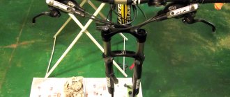
REMOVAL AND INSTALLATION OF FRONT FORK
The front fork is removed for replacement or repair if there are cracks in the fork leg pipe or in the steering column bridge, oil leakage through the oil seals, the fork leg tips moving relative to the pipe axis by more than 8 mm, if the threads on the shock absorber rod are broken and the fork spring is broken.
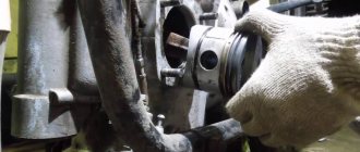
To remove the front fork: remove the front wheel and brake drum cover, disconnecting the front brake cable from it; unscrew the nuts of the signal mounting bolt and remove the bolt; remove the steering wheel by unscrewing the nuts securing the steering wheel brackets and place it on the gas tank; unscrew the long wing bolt of the steering shock absorber and remove the shock absorber parts, unscrew the steering column rod nut; remove the instrument panel, having previously removed the sockets of the warning lamps, the speedometer backlight lamps and unscrewing the speedometer drive shaft (for the Ural M-67 motorcycle); unscrew the nut securing the front bracket of the sidecar frame fastening rod and remove the bracket (for the Ural M-62 motorcycle); unscrew the tightening nuts of the fork legs, remove the washers and crossbar; unscrew the bolts securing the shield to the skin and the bridge of the steering column; remove the bracket for the turn relay and fuse box and the front shield; headlight, unscrewing the bolts securing it to the casing bracket; disconnect the wire from the turn signal terminal. To preserve it from damage, the gate indicator is removed from the front fork (for Ural M-67 motorcycles); from"
turn and remove the central switch from the casing bracket; unscrew the bearing nut and remove the protective washer of the thrust ball bearing (while unscrewing the nut, support the front fork); remove the upper bearing ring; pull down the front fork. When removing the steering column rod from the column itself, be careful not to scatter the balls of the thrust bearings.
Reinstall the front fork in reverse order. When assembling the steering column, make sure that all 48 thrust bearing balls are in place and are not knocked down during assembly. The balls collected in the bearing must be lubricated with Litol-24. Tighten the bearing nut so that the fork rotates easily in the bearings without any jamming, but there is no noticeable gap (tighten until full, and then release 7b-78 turns). The gap between the fork stays (at its extreme positions) and the walls of the gas tank should be uniform, 3...7 mm.
REMOVAL AND INSTALLATION OF STEERING STEERING WITH CONTROL CABLES
The steering wheel assembly is replaced if the following defects occur: a broken or bent steering tube that cannot be straightened.
To remove the steering wheel (Fig. 9, a, b) with all control cables, it is necessary to: remove the gas tank, disconnect the control cables from the carburetor throttle valves, the clutch cable and the front brake cable from the brake drum cover, for which screw in the adjusting screw and install so that its slot coincided with the slot of the bracket. By squeezing the brake lever on the cover, remove the tip of the cable sheath from the socket in the adjusting screw and remove the tip of the cable from the lever; disconnect the ignition timing cable (for Dnepr K-650 and MT-9 motorcycles) and the light switching cable, the signal wire, then unscrew the nuts securing the steering wheel brackets to the fork cross member and remove the steering wheel.
Install the steering wheel in the reverse order.
The handlebars must be installed symmetrically to the longitudinal axis of the motorcycle frame and firmly fixed in the brackets. The bracket, in turn, is firmly attached to the fork crossbar. When making extreme turns of the fork, the steering wheel should not touch the fuel tank.
A lever fork is one of the main attributes of any stroller, and certainly a shit climber can’t do without it. For example, in the West, people generally cannot imagine a motorcycle with a sidecar equipped with a telescopic fork - for them the lever is the first gadget that needs to be installed on the sidecar alone.
General form
.
Of course, I’m not a designer, and I don’t have any special knowledge. This article is written from the perspective of an ordinary person, and may contain many erroneous ideas. The “drawings” given here are also probably not drawn very correctly, but if anyone is interested, then in the future I can post a 3D model of the product in 3dm Rhinoceros format. I’ll say right away that the fork was originally made with a very critical error, as a result of which it broke at the most inopportune moment. This led to an accident, but fortunately no one was injured. I'll talk about this at the very end of the article.
So, making a lever fork is the easiest way to get a durable, long-travel motorcycle fork. However, despite the apparent simplicity of its design, I personally encountered unexpected difficulties, which, however, I was able to overcome after understanding their cause.
A friend gave me 2 ready-made feathers and a pendulum blank, and I started from these details when developing my product.
My tasks were as follows:
- Increase ride comfort over uneven surfaces;
- Raise the front of the motorcycle as much as possible. This was required to increase clearance;
- Reduce the overhang (trail) to the minimum acceptable value in order to facilitate steering both on bad roads and on asphalt;
Based on these tasks, using CAD, I quickly made a model of the fork along with the motorcycle frame, checked everything, and made a swingarm from a round pipe. But this pendulum did not satisfy me with its low rigidity, so I threw it away. I had to redraw the project and weld a new pendulum from a St-3 25x40x2 profile pipe. This pendulum turned out to be very rigid. The only place in it that requires explanation is the bushings under the wheel axle. The bushings are solid, steel, and the axle is simply passed through them and secured with a nut. The wheel and brake drum are secured against axial displacement by a spacer sleeve. The axle play is eliminated using brass bushings that I made from 12 gauge brass sleeve.
Lever fork
I assembled the pendulum in a certain order. First the end tubular sections were cut out, then I welded the bushings to them. After this, the welding points between the bushings and the pendulum were reinforced with side plates, welded in a circle. Then, having threaded the axle through the bushings, I welded the main sections of the pendulum to the end sections. The next step is welding the shock absorber mounting ears. In the end, I realized that it was easier to install the ears on a fully assembled swingarm, and welded the rear bridge to it. It was then that I encountered the problem of the product moving away during welding, but I easily straightened the bent pendulum using a jack. Then I installed reinforcing pads under the ears for attaching the feathers, and then the ears themselves. Next, it remained to install the gussets on the connections of the pendulum jumper, and I did this, spreading its ends with a jack so that it would not move away. All ears should be welded by passing a pin through them to control the location of all parts; It is convenient to measure the size from the inserted wheel axle.
Pen sizes
Pendulum dimensions
Pendulum
Next, I installed the upper shock absorber mounting lugs on the stays, and my fork, in general terms, was ready for fitting. I decided to install silent blocks in the bushings of the feathers, but I couldn’t find anything suitable in auto stores. Silents had to be made from scrap materials: the rubber bushing of the passenger footrest was ideal, and steel bushings with an internal diameter of 12 mm were found on the farm. The wheel axle was made from the rear wheel axle, the “thick” part of which had to be ground 30mm so that the long narrow part, 20mm in diameter, would fit through both bushings.
Now I must say a few words about shock absorbers. Initially, I lengthened the standard Ural shock absorbers, and replaced the “native” mount with a silent block. A silent block on a tube leg was attached to the body by welding. I will not describe all my torment associated with selecting the optimal shock absorber length, but I will say right away that it is now 370mm. Subsequently, on one of these ancient KMZ products, my stem broke, and I replaced them with a Chinese analogue. I also welded tubes for silent blocks onto their lower mount. A little more time passed, and I replaced the Chinese dinners made from someone’s feces with old Soviet ones. From that moment on, everything became good, and I have been driving these shock absorbers for a year now without any problems.
Assembled
The reaction rod of the brake shield is attached to the pendulum. On the one hand, this solution seems good to me, since it does not require any additional tricks. Usually the rod is attached to the feather, and this necessitates allowing the shield to swing relative to the pendulum. In my case, the shield always remains motionless and can be tightly clamped between the bushings of the pendulum and the hub. In general, the anti-dive of the fork is regulated by the location where the torque rod is attached. In my case, when braking, the motorcycle not only doesn’t bite, but on the contrary, it lifts its nose. That is, the force stretching the fork is too strong for me. But since I use standard, very sluggish brakes, I’m not worried about the health of the suspension. In practice, I have never experienced any “reverse breakdowns” in shock absorbers. If you attach the reaction rod a little higher, on the feather, you can ensure that the motorcycle does not receive any trim at all when braking.
Jet thrust
So, I installed the entire structure on the motorcycle, figured out how the wing would be attached, and welded the corresponding ears to the feathers. Now the tests could begin.
Ural
At low speeds on a dirt road, the motorcycle behaved just fine, but as soon as I accelerated, I lost all control over the car, I began to wobble from side to side, as a result of which I almost rolled over. Obviously, this is how problems with the geometry of the fork manifested themselves, namely, with its offset, or trail. Through various observations, measurements, modeling and experiments, I realized that too weak shock absorber springs, as well as unadjusted rebound valves, were to blame. At low speeds, the shock absorbers at least managed to work out all the irregularities and return to their original state, but as the speed increased, they no longer coped with their job and were constantly in a semi-compressed state.
The fact is that a lever fork with a geometry like mine, when the pendulum rises on uneven surfaces, tends to greatly reduce the reach. With strong compression of the shock absorbers, it decreases to almost zero, and sometimes can reach negative values. Naturally, this causes loss of control of the motorcycle at high speed.
Reach change when shock absorbers are compressed
I solved the problem simply. It turned out to be sufficient to adjust the shock absorber valves and increase the spring preload to increase their stiffness. I tightened the springs by 15mm, placing spacer rings under them. 15mm was taken based on the fact that the shock absorbers sagged exactly by this amount when I sat on the motorcycle tank.
As I wrote above, this improvement led to a break in the rod of one of the shock absorbers: old Soviet shock absorbers, in fact, are almost impossible to adjust. They were replaced by the Chinese with good Soviet springs and the same spacer rings.
Not knowing grief, I traveled all winter, and then, in the spring, we went to the Smolensk region. It was then that trouble happened to us. On a very rough road, both forks broke, causing the motorcycle to overturn. At first we didn’t quite understand what had happened, since the fork did not fall apart, but after driving another 500 meters and flying into a ditch, we realized that something was wrong here.
And indeed, an autopsy showed that both “crowbars” were cracked along the groove that was made so that they would fit into the cross beams. The cause of the breakdown was obvious. A sharp step between two diameters served as a stress concentrator. Due to constant vibration and stress, mainly aimed at “bending” the feathers, cracks appeared on their back side. The chainstays straightened out, the trail became negative, and the motorcycle lost control.
Repair
All this could have been avoided if the transition from one diameter to another had been smooth. But ideally, cuttings were also needed, which would relieve the feathers. The broken fork was promptly welded, I also welded these same cuts from the fittings. After that, she traveled another thousand kilometers, and upon returning home, I immediately rushed to my friend, who helped me make this fork, to make new powerful feathers.
Incorrect and correct options for cutting a pen
To make a completely indestructible fork, we welded feathers from “crowbars” from a standard Soviet “telescope”. One lever pen requires one and a half telescopic crowbars. They are connected using bushes secured with electric rivets. Next, the connection is scalded. We retained the original geometry. The difference with the old feathers was the absence of any grooves and the presence of bevels made from pipes. Since the lower traverse is located inside the resulting diamond, it is not removable. That is, the fork can no longer be completely disassembled - the lower yoke is movable, but it will remain with the fork forever.
After this improvement, any problems disappeared, and since then I have been driving without fear.
It was broken
It won't break - it has become so
Messages [ 12 ]
1↑ Topic from Roma 02/26/2013 19:40:52
- Roma
- Uralomaniac
- Inactive
- Name: Roman
- From: Shentala, Samara region.
- Registered: 23-10-2012
- Posts: 6,151
- Reputation: 517
- Motorcycle: Ural IMZ 8.103-10
Topic: Removing the stays and stay covers from the Ural motorcycle.
So. I think beginners and those who have never performed this operation will be interested to know how to do it. First, place the motorcycle on the center stand and remove the headlight. So that the motorcycle becomes like this
We jack up the front end so that the front wheel comes off the ground.
Remove the wheel and fender. I removed the wing. To make it even more convenient
Then loosen the feather clamps. They are under the headlight, on each feather separately. It's a front bolt
And this is it on the other side, with a nut screwed onto it
The nut is 17, the bolt is 13. Hold the bolt and unscrew the nut.
Now unscrew the nut - the plug. It's under the steering wheel. So big shiny
I turned it off with this key, it comes with the motorcycle.
If you don’t have such a key, then the nut is 36. When you unscrew it, hold the pen. It may simply fall out. Unscrew it and pull the pen down.
That's all. The feather has been removed. Don't drop it or oil will spill out of it. Wrap the nut - the cork into the feather. So as not to lose. Now the casing remains
Just pull it to the side and it will come off.
Reassemble everything in reverse order. The left nib and shroud are absolutely the same. Just before removing the casing you need to unscrew the ignition switch, it is held in place by two bolts
That's all.
Edited by Roma (26-02-2013 19:42:11)
+4
2↑ Reply from Dragon 02/26/2013 19:59:44
- Dragon
- Pro
- Inactive
- Name: Max
- From: Troitsk
- Registered: 10-01-2013
- Posts: 680
- Reputation: 28
- Motorcycle: Dnepr MT 11
Re: Removing the stays and stay covers from the Ural motorcycle.
3↑ Reply from Shaman 02/26/2013 21:10:14
- Shaman
- Repressed
- Inactive
- Name: Dmitry
- From: Teykovo 37 region
- Registered: 02/13/2011
- Posts: 1,346
- Reputation: 86
- Motorcycle: imz 8.103-40, dnepr 11
Re: Removing the stays and stay covers from the Ural motorcycle.
And Roma looks like a mechanic
4↑ Reply from Roma 02/26/2013 21:12:23
- Roma
- Uralomaniac
- Inactive
- Name: Roman
- From: Shentala, Samara region.
- Registered: 23-10-2012
- Posts: 6,151
- Reputation: 517
- Motorcycle: Ural IMZ 8.103-10
Re: Removing the stays and stay covers from the Ural motorcycle.
And Roma looks like a mechanic
Come on, what are you doing?
I just made an article. Maybe it will be useful to someone
5↑ Reply from drakone 02/27/2013 05:42:41
- on drakone
- Elder
- Inactive
- Name: Albert
- From: Omsk region. Omsk city
- Registered: 07-12-2012
- Posts: 4,972
- Reputation: 125
- Motorcycle: Ural 8.103.10, GAZ 31029
Re: Removing the stays and stay covers from the Ural motorcycle.
Just pull it to the side and it will come off. Well, some of them will come off and some of them will be crushed with a sledgehammer
And Roma looks like a mechanic
Come on, what are you doing?
I just made an article. Maybe it will be useful to someone
Ahaha
.what’s wrong with one more mechanic. linking them together creates a mechanism
6↑ Reply from SANYa pif 02/27/2013 06:41:39
- SANYA pif
- Elder
- Inactive
- Name: Alexander
- From: Bely, Tver region.
- Registered: 06-02-2013
- Posts: 4,926
- Reputation: 302
- Motorcycle: Ural 8.103.10
Re: Removing the stays and stay covers from the Ural motorcycle.
Roman, once you go through the fork, then go through the steering column carefully. I found an article here that might be of interest.
As you may have guessed, today we will talk about the steering column of the above-mentioned motorcycle, and to be precise, about its next sore. The whole issue is that the “Ural” refers to heavy motorcycles, plus a side trailer. And from this it follows that the load on the steering column is very significant, and based on our own experience, it can be safely multiplied by three or even four times. Judge for yourself:
How to remove a fork from a Ural motorcycle
Removing and installing the front fork of a Ural motorcycle
IMZ-8.103-10
To remove the front fork, you need:
remove the front wheel and brake drum cover, disconnecting the front brake cable from it;
remove the steering wheel by unscrewing the nuts securing the brackets and place it on the tank;
Unscrew the steering shock absorber tightening bolt, remove the spring and support washers and unscrew the steering column rod nut;
remove all steering shock absorber washers;
unscrew the flexible shaft from the speedometer, having first removed the cartridges from the speedometer backlight lamps;
remove the instrument panel, having first removed the sockets with warning lamps;
unscrew the tightening nuts of the fork legs, remove the washers and crossbar; unscrew the nuts securing the front shield to the casings and the steering column bridge, remove the bracket from the turn relay, remove the bolts from the casings and remove the shield;
disconnect the turn signal wire. The turn signal is removed as necessary;
unscrew the screws and remove the ignition switch from the fork housing; remove the headlight, disconnecting the wires, and unscrew the bolts securing it to the casing brackets;
Unscrew the bearing nut, remove the protective washer (support the front fork while unscrewing the nut) and the upper wheel of the thrust bearing;
remove the front fork. When removing the rod from the steering column, make sure that the balls of the upper and lower thrust bearings do not fall apart;
remove the thrust bearing balls.
Reinstall the front fork in reverse order. When assembling the steering column, make sure that all the balls of the thrust ball bearings are in place and are not knocked down during installation.
The balls assembled into the bearing must be lubricated with LI-TOL-24 lubricant. The nut must be tightened in such a way that the fork rotates easily in the bearing, but there is no noticeable play (tighten until it stops and then release 1/8-1/6 of a turn).
Source
The very beginning - the frame
I greet everyone, ladies and gentlemen, who is not indifferent to domestic technology. Today I want to talk about small modifications to the frame for my future motorcycle. So after completely disassembling the motorcycle, I set about finalizing the skeleton for my project. First of all, I removed the homemade terrible side stand and cut off the welded mount under it, then cut off the plate on the right where the charging relay was attached since it will interfere with me in subsequent modifications, then I completely cut off the steering column lock (I have it, like 99% of owners This Pepelaz didn’t have a key, and I don’t see the point of having one on a stroller), and there was a case when a friend apparently had a spring burst and the lock jammed the steering wheel while driving and he got into an accident. I completely removed the lock (though there was still a hole where the pin went in, but this is not so scary because there is welding work ahead).
Then I started trying on the parts that I plan to install on the motorcycle in the future. Namely, a bracket for symmetry for the second arc, like on the Ural Tourist motorcycle, suddenly you want to ride alone (the bracket was cut from the donor frame)
I tried on and marked the area for attaching the side panels so that nothing would interfere with them, and so did they.
I found a place for a side stand (again useful for a single person)
Marked the mounting locations for the seat platform
And of course, I decided to strengthen the lower cross member of the frame where the center stand bracket is welded, because this is their disease. The motorcycle is quite heavy, and when you put it on the stand, for example to remove the rear wheel, there is so much pressure from the lugs of the stand that the tube on one side is dented and on the other it just starts to tear. My pain was so pronounced that the footrest simply turned inside out. I completely cut out the tube and in its place asked the turner to turn a solid round piece, so as to be sure. The last part cut was the seat bracket, which is located near the tank, since I had a solid saddle, and although I plan to leave the same one, it would not hurt to be able to replace it with separate ones if desired, and even with minimal loss of time and without the use of welding. Fortunately, in modern Urals, this problem has been solved by installing a unified platform with the ability to screw a separate saddle bracket to it and adjust the fit (closer or further from the steering wheel). The photo is just above...
After trying it on, I began making different fasteners:
1) Under the seat I prepared two strips onto which the platform will be screwed
2) On the sides in the area of the battery, I prepared two small plates behind the covers for the possibility of attaching some small things.
3) Under the tank, along the top pipe of the frame, I prepared a plate to allow the installation of relays there to relieve the load on the electrical system.
4) Prepared brackets (factory-made) for installing safety bars produced by KBMTS
5) Prepared the side stand bracket from the “Wolf” for subsequent welding to the frame, because It has been verified that if you simply screw it to the engine mounting stud, then under the weight of the motorcycle it begins to turn inside out and simply tear the metal.
6) I prepared a round timber instead of the old tube for installing the central step, as well as the bracket itself for it.
After a test fitting of the parts and marking out where the frame would be attached, I took the frame to a welder I knew and together with him we got to work. We welded everything just fine and welded some old seams, welded the hole for the steering column lock.
Then, after the welding work, I returned to the garage and refined the welding seams and trimmed some brackets.
Even the use of partially painted parts with the use of modern fasteners significantly transforms the old frame. Now it is ready for sandblasting and powder coating, but unfortunately some difficulties greatly slowed down my work and the frame had to be placed in a corner for an indefinite period.
I thank everyone who read my entry simply by chance and, of course, regular readers, everyone has full tanks and a great mood, I hope I won’t make you wait long for the next entry.
Tags
- Ural
- frame
- restoration
- welding
- bracket
- step
- lateral
- covers
- revision
- area
- separate
- solid
- fastener
- arcs
- tourist
