Clutch adjustment Moto Dnepr
MAIN FAULTS IN THE CLUTCH OF MOTORCYCLES “URAL”, “DNEPR”
The smooth operation of the clutch depends on the correct adjustment of its drive mechanism. If the drive cable is pulled too tight, the clutch slips; if the cable tension is insufficient, the separation of the clutch discs is incomplete (the clutch is driven). These defects can be corrected by proper adjustment.
Failure to operate the trigger mechanism is possible due to a break in the rotary spring or its release from sleeve 1 (Fig. 4.6). In this case, the lever itself does not return to its original position, but it can be lifted up by hand. The defect is eliminated after disassembling and inspecting the box.
If the trigger pawl is broken, the lever moves down freely and the engine crankshaft does not rotate. The same thing happens when the pawl spring breaks or due to increased oil thickness.
Loosening of the tightening of the wedge connection of the lever with the trigger shaft is eliminated by additional tension of the wedge bolt.
Increased, monotonous, high-pitched noise during operation may occur due to wear on the working surfaces of the gear teeth. Without load this noise disappears. This noise is not dangerous, but unpleasant and to remove it, the gears are replaced. The source of the noise may be a worn bearing. Self-disengagement of gears may occur due to wear of the splined connection of the gearshift clutch.
REMOVAL AND INSTALLATION OF THE CLUTCH RELEASE MECHANISM OF MOTORCYCLES “URAL”, “DNEPR”
To remove the clutch release mechanism, it is necessary to dismantle the clutch release lever, having previously uncoiled and removed the lever axis, unscrew the lever adjusting bolt, press the front end of the clutch release rod and remove the thrust slide
ball bearing, tip and rod. Wash, inspect, replace defective parts. The clutch release mechanism is assembled in the following sequence:
- lubricate all parts, install the tip, bearing and slider with a rubber ring into the hole in the input shaft at the rear, then install the clutch release lever on the gearbox cover;
— insert the axle and pin it;
— screw the adjusting bolt into the lower head of the lever, insert the clutch release rod with a rubber seal into the hole in the input shaft from the front so that it protrudes from the shaft by 50-60 cm; adjust the gap between the spherical end of the adjusting bolt and the intermediate rod.
• HOW EASIER IS IT TO DISASSEMBLE AND ASSEMBLE A CLUTCH?
To gain access to the clutch parts, remove the rear wheel, reverse gear, and gearbox. Then remove the 6 countersunk screws that are screwed into the engine flywheel pins. For this operation, a massive screwdriver and a hammer are used, because... screw heads are cored. A simple device helps to significantly facilitate the operation, and most importantly, to eliminate deformation of fingers and screws (Fig. 4.4). It consists of a steel strip 1 with a bolt 2, the pointed end of which is sharpened in the form of a screwdriver blade and hardened. Additionally, you need 3 bolts 40 - 50 mm long with M8x1 thread (like standard disk mounting screws) and 3 nuts for them. After dismantling the rear wheel, main gear and gearbox, you need to put bar 1 on the two freed upper studs of the engine crankcase and secure it with the previously removed nuts, without screwing them in completely. Screw bolt 2 into it, bring the disc fastening screw to it, turning the shaft and, directing the blade of bolt 2 into the screw slot, tighten the nuts. Then unscrew the bolt together with the screw. In the same way, remove two more screws (one at a time) and remove the rest. Instead of the removed screws, install 3 bolts with nuts and compress the disks, tightening the nuts. Remove the three remaining screws, and then gradually unscrew the nuts until the discs are free. The clutch is assembled in the reverse order: tighten the discs with technological bolts and nuts, secure the discs with three screws, remove the bolts, install the remaining three screws
and, using the device, finally tighten them. To ensure the exact position of the disc teeth, it is necessary to insert the old gearbox shaft into the disc hole before tightening the screws.
IS THERE A WAY TO TIGHTEN LOOSE CLUTCH DISC SCREWS WITHOUT DISMOUNTING THE MAIN TRANSMISSION AND CARDAN?
In Ural motorcycles, the screws securing the clutch disc often loosen spontaneously, which causes a sharp knocking noise. The “Operation Manual” recommends removing the gearbox to eliminate the defect, which means first dismantling the wheel, main gear and cardan. There is no need for this labor-intensive work if you drill a hole with a diameter of 22 - 24 mm in the lid of the box (Fig. 4.5). Having loosened the fastening of the box (by unscrewing three nuts and one bolt), move it away from the engine by 3 - 4 mm so that it does not interfere with Fig. 4.5. Gearbox: loose screw on the clutch. Then 1 - box fastening nut; bring the screw to the hole, pressing on the hole, tighten and securely seal the screw, and then close the hole with a suitable plug, secure the box.
MY MOTORCYCLE
So, the advantages of a driven tavrodisk are the presence of a spring damper. Its (damper) location “before” the gearbox smooths out torsional vibrations on the shafts of the gearbox itself, which is not actually observed if only a rubber damper is installed “after” the gearbox.
I think that with this scheme the box will work a little longer. Well, I emphasized that this is not “nuno”, but “mono”.
But let's take things in order.
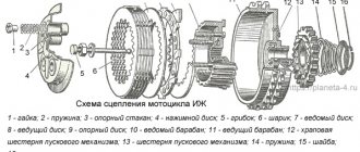
Our standard clutch looks something like this (springs and screws are not shown):
Somehow something started ringing in my engine at very low speeds and with the clutch depressed. The book didn’t tell me anything about this, except that you can drive further, and if necessary, check it out. Well, on occasion, on occasion. It turned out that there was nothing catastrophic there. The middle steel drive disc begins to ring when the holes on it become slightly broken. And this happens very soon.
Let's go further. All this talk to me about installing a disk from Tavria... I couldn’t find any proper information, so I decided to draw everything myself.
Let's first consider the disc itself from the brand.
It consists of two plates that hold springs; a central plate that “hangs” on these springs; a splined bushing, which is cleverly pressed into the central disk; disc-bracket for the friction discs themselves; a centering plastic sleeve (purple in the picture); washers with whiskers and a spring washer. All THIS is assembled with rivets.
Let's get started.
The spline bushing is pressed out of the central disk with three blows of a hammer. We give the plate itself to the turner to grind the inner hole (the teeth must be cut off).
Next, we remove the bushings from our original MT driven disks, cutting off eight rivets with a grinder.
These bushings need to be machined. We also give them to the turner, showing the following diagram...
They need to be machined one and a half millimeters, or a little less, from the chamfer side of the holes, and the diameter must be such that they are pressed into the central disk.
The diagram also shows the new centering sleeve. It needs to be made of duralumin or bronze so that it is pressed onto the MT spline bushing.
Then it gets more interesting. The MT bushings must not only be pressed in, but also secured in the central plate. To do this, in the latter we will need to drill eight holes with a diameter of 5 mm. The plate is basically calcined. We take a victorious drill and remove the side cutting edge on it. Next, using our machined bushings as a template and as a guide for the drill, slowly pouring oil on us, we drill the central plate at very low speeds. Because the holes hit the edge of the metal, the drills experience extreme side load. I ruined four pobedit drills :))))…
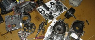
The photo shows the actual central plate on which we drilled and broke :)), and turned MT bushings.
When you mount the bushings into the central disk, pay attention to the fact that they need to be turned so that the holes of the two bushings and their splines coincide. Drilled? Now remove the chamfers on the bushings for the rivets, and rivet the bushings with the central disk. Next you need to remove a 1x45 degree chamfer from the “inner” side on one of the spring holder plates to install the centering sleeve. All that remains is to press on the centering sleeve itself and put it all together.
Well... We made the driven disk itself.
Let's see in the diagram how this is all installed.
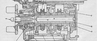
Sectional diagram of the modified clutch, on the right - the standard clutch.
The sequence of discs is: release, intermediate drive from the standard set, driven (already T-type) and drive, which is screwed to the flywheel. The driven disk may rest against the box (as in the case of using the Moskvich one), so you may have to shorten the flywheel pins. Or you can simply put another intermediate drive between the driven (already branded) and the drive, which is screwed to the flywheel. But this will make the whole set heavier, which may affect the dynamics.
I’ll say right away that I sharpened the flywheel. I cut off the outer shell and increased the groove “around” the fastening bolt. This lightened the flywheel by one and a half kilograms.
Before shortening the flywheel pins, ALWAYS make sure that the gearbox drive shaft is long enough for such a disc offset.
If you intend to install a starter, check whether there is room for its crown.
By the way, sometimes there is talk about installing a Moskvich disk (401 or 408), in which the splined bushing matches the teeth one to one with the MTshnoy. But they also say that its damper works “in the wrong direction,” and therefore, with such a disk, the gearbox shafts fly, in the absence of a rubber washer after the box. But it is impossible to turn the disk over due to its specific dimensions. I haven't tested it in metal. That's just what they said.
Sketch of a standard flywheel with some dimensions.
The article is purely informational for those who like to get technical, so don’t be biased. And taken from the first person in a slightly shortened form.
Author: SerDUKE, source: MOTO.kiev.ua
How to properly monitor the Dnepr gearbox
10/26/2014 NEMEC Add a comment
4705
“Dneprovskaya” (MTovskaya among the people) has proven itself on the positive side and is a success. Even I was looking for just such a gearbox for my Cacique, because I don’t have a rear one and it’s difficult to find neutral. Yes, and it adds a little speed (Dnepr gearbox). For this case, I will publish a post about how to properly maintain the MT gearbox.
Since 1971, the plant has installed the MT804000 gearbox with reverse gear and a forced clutch release mechanism when changing gears on all Dnepr motorcycle models. Maintenance of this box is easy. The main thing is to always check and monitor the oil level using the dipstick. In a working box, it is practically not consumed, but the occurrence of an accidental leak can lead to failure of the unit. So keep a close eye on him. At the factory, the box is filled with M8A GOST 10541-78 engine oil. The first oil change is made after 500 kilometers in order to remove the products of running-in parts along with it. In the future, under normal operating conditions, it is changed after 5 thousand kilometers. If possible, it is better to use transmission oils TAD-17 or TAP-15V, which have twice the service life (10 thousand kilometers). During operation, it is necessary to monitor the adjustment of the forced clutch release mechanism. Failure to adjust is possible due to wear of parts, especially those that operate without protection from dust and dirt.
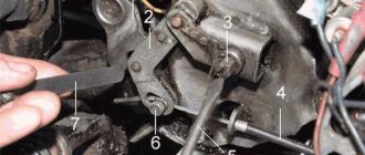
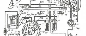
A few words about the operation of this mechanism. When changing gears, the cam-crank 2 (Fig. 1), connected to the shift pedal 1, turning forward or backward from its middle position, raises the long arm of the lever 4 with roller 3. The short arm of this lever acts on the composite intermediate rod 5, which has an outer the end presses on the adjusting bolt 6 of the outer clutch release lever 17. The latter, swinging on the axis 18, acts on the clutch release rod 12 through the slider 16, bearing 15 and tip 13. In the design of the mechanism, the regulating element is bolt 6. It must be screwed in so that there is a small gap between its end and the end of the intermediate rod 5, ensuring free play of the front arm of the shift pedal of no more than 10 mm. The adjusting bolt must not be screwed in too deeply until the free play disappears, since in this case the thrust bearing 15 will be clamped between the slider 16 and the tip 13, and the pressure plate 8 will be pressed away from the flywheel by the clutch release rod. As a result, the bearing and clutch of the Dnepr motorcycle may fail when it slips. It is also impossible to do so that the adjusting bolt is not tightened and the free play of the pedal exceeds 10 mm. This will lead to shocks and jerks when changing gears in cases where the driver does not use the manual clutch release, and in addition, the clarity of shifting will be disrupted.
“Correct” clutch driven disc.
It is traditional for us to install a disc from a 408 Muscovite as a clutch disc with a damper. Accepted and accepted, I installed one for myself. And the other day I came across several discs from various cars (I was looking for them as donors for diaphragm kits), including those with interesting dampers, namely dampers that have a progressive (albeit stepwise) characteristic. At low torques, “weak” springs work; at increasing torques, stiffer ones are connected.
This disk is already gone:
The spline is from a Muscovite, the disc itself, judging by the markings, is from 2110. It can be seen that only two weak springs are immediately put into operation. They are compressed before connecting the first pair of rigid springs with a force of 15 Newtons per meter. The last two pairs of rigid springs are activated at a force of about 80 Newtons per meter. Full compression is about 200 Newtons.
For comparison, the clutch disc damper from the Muscovite 408 begins to rotate with a force of 50 Newtons. It is clear that it will not dampen vibrations of our engine, which has a torque of less than 50 Newtons per meter; the maximum is to dampen shocks when throwing the clutch when the throttle is open and when it is released during the transition to engine braking. No more.
The disk damper, the photo of which was given above, will dampen vibrations over the entire range of transmitted torque.
But I will install such a disk for myself, here is a photo of its damper:
The spline is made in separate detail and is spring-loaded with small springs relative to the main damper. The damper itself consists of two long-stroke springs (they begin to compress at a force of 10 Newtons per meter) and four paired rigid springs (they are activated at a transmitted moment of 70 Newtons per meter). The damper has a very long stroke. It turns out that relatively soft and long-stroke springs will operate throughout the entire range of transmitted torque in all driving modes. If there is a sharp increase in the transmitted torque (you dropped the clutch during acceleration, drove into a hole, etc.), the stiff springs will be activated.
IMHO such driven discs should work and prolong the life of the transmission much better.
Source
How to properly tension the clutch cable.
I searched the forum, but didn’t find or didn’t notice similar questions. A question has appeared. How to properly tension the clutch cable so as not to overtighten it or become too weak. Who exhibits what?
2↑ Reply from Ural*4uK 04/22/2013 15:32:06
- From: Russia, Bryansk region, Mglin
- Registered: 03-03-2012
- Messages: 1 451
- Reputation: 39
- Motorcycle: Ural IMZ 8103 with sidecar
Re: How to properly tension the clutch cable.
at the end of the cable, above the box, there are adjusting nuts - you will understand how and where to turn. and on the steering wheel (on the clutch lever) you make a free play of 2-3 mm and that’s it
3↑ Reply from Student 04/22/2013 15:42:49
- From: Engels
- Registered: 11-04-2013
- Messages: 267
- Reputation: 3
- Motorcycle: Dnepr MT 10, Dnepr MT 11
Re: How to properly tension the clutch cable.
What are the signs that the cable is too tight? Or do I need to tighten it a turn?
4↑ Reply from PATRIOT 04/22/2013 16:25:59
- From: Krasnodar region, Krasnodar
- Registered: 18-02-2011
- Messages: 3 148
- Reputation: 180
- Motorcycle: No. Next will be the K750!
Re: How to properly tension the clutch cable.
at the end of the cable, above the box, there are adjusting nuts - you will understand how and where to turn. and on the steering wheel (on the clutch lever) you make a free play of 2-3 mm and that’s it
What another 2-3mm. If I'm not mistaken, all my life the clutch free play was 5-8mm!
IMZ Ural motorcycle clutch, device, principle of operation, design features.
The clutch of the IMZ Ural motorcycle is designed to smoothly connect and disconnect the engine with the transmission when starting the motorcycle and to change from one gear to another, as well as to limit the torque transmitted from the engine to the transmission and vice versa.
IMZ Ural motorcycle clutch, design, principle of operation, design features, catalog numbers of clutch components and parts.
IMZ Ural motorcycles use a dry double-disc clutch. The drive disks (pressure, intermediate, thrust) are made of steel. The working surfaces of all disks are polished. There is a square hole in the center of the pressure plate. And in front there are grooves for springs. The pressure and thrust discs are centered on the flywheel pins and can move freely along them in the axial direction.
The thrust disk is attached to the fingers with countersunk screws. The screws are secured by punching the metal of the disk into the screw slot. To ensure proper assembly of the clutch and to maintain the balance of the flywheel and clutch, marks are placed on the discs and on the annular edge of the flywheel with a core. Which are combined during assembly. Friction linings are molded to the steel driven disks and splined hubs are riveted to transmit torque.
The clutch release rod has a square shank, which prevents the rod from turning in the pressure plate. The rod together with the tip rotates relative to the slider in the thrust bearing. The slider, under the influence of the lever, moves forward axially and through the bearing. The tip and rod move the clutch pressure plate and separate the discs. As a result, the transmission of torque stops.
Clutch device of the IMZ Ural motorcycle.
If the force is removed from the lever, then under the action of the springs the disks move backward. Returning the rod, tip, bearing, slider to their original position. The disks are pressed against each other by springs. In this case, friction forces arise, which transmit torque. If the lever is released smoothly, the discs are pressed against each other gradually. Friction forces increase smoothly, torque will increase gradually. Due to which the motorcycle moves off smoothly.
If the torque exceeds the calculated value, for example due to the inertia of the flywheel at high speeds, then when the engine and transmission are rigidly connected, destruction of parts may occur. If there is a clutch, if the calculated torque value is exceeded, the friction forces of the disks are not enough to transmit such a torque. The discs slip relative to each other, protecting parts from destruction.
A simple way to assemble a clutch
In general, opposition brothers, due to numerous requests, I am laying out the procedure for assembling the clutch using two bolts. Actually, when I was young and stupid, I thought that this system was the first to invent, but when I got to Opposite, and also after talking with comrades, I realized that there is no smell of a patent