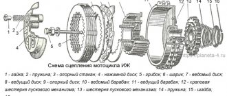
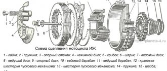
Dnepr motorcycle clutch diagram
Chapter IV.
TRANSMISSION OF MOTORCYCLES “URAL”, “DNEPR” The transmission is designed to transmit torque from the engine crankshaft to the wheel (wheels) of the motorcycle, change it and stop the transmission of rotational force.
The transmission consists of a clutch, gearbox, driveshaft and final drive.
CLUTCH OF MOTORCYCLES “URAL”, “DNEPR”
The clutch is designed to transmit torque from the engine to the gearbox, disconnect the engine from the gearbox during gear changes, and smoothly engage when the motorcycle is moving away. The double-disc dry clutch consists of driven and driven parts and a clutch release mechanism.
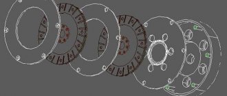
Rice. 4.1. Clutch discs of the motorcycle “Dnerpr-11/16. 1 — disk assembly; 2 - hub; 3, 5, 6, 7 - disks; 4 - spring; 8 - screw; 9 - rivet
Rice. 4.2. Clutch release mechanism: 1 — cotter pin; 2 — washer: 3 — ring; 4 - slider; 5 - bearing, 6 - tip; d 1 - rod, 8 - oil seal; 9 — rod assembly, 10 — lever; 11 - bolt; 12 - nut; 13-axis
The need to check clutch parts arises if the clutch pins and pin holes in the drive discs wear out, the pin fits in the flywheel become loose, the splines in the hub of the driven discs wear out, the fastening of the disc hubs becomes loose, the friction discs wear out and the elasticity of the springs decreases. If the fingers are worn out by more than 1 mm, they need to be replaced. To do this, press out the worn pins, having previously measured the amount of protrusion of the ends relative to the plane of the flywheel. Press in new fingers (Fig. 4.3), leaving an allowance at the ends for grinding. Then the fingers are polished. After grinding, the ends of the fingers should be in the same plane. The runout of the ends relative to the conical seating surface of the flywheel should be no more than 0.2 mm. If the walls of the holes in the drive disks are damaged, then you need to drill new holes with a diameter of 196 mm between the old ones (hole diameter 12.5 - 12.57 mm). Discs with worn out linings and splines in the hub are replaced with new ones. If rivet connections become loose, they must be riveted or replaced. Clutch springs must have the same stiffness. New parts, when compressed to 21 mm and depending on the load, are marked with paint: 17.5 - 19.0 kgf - gray, 16.0 - 17.5 kgf - black. The free springs are about 45 mm long.
Source
content .. 31 32 33 ..Chapter IV. TRANSMISSION OF MOTORCYCLES “URAL”, “DNEPR”
The transmission is designed to transmit torque from the engine crankshaft to the wheel(s) of the motorcycle, change it and stop the transmission of rotational force.
The transmission consists of a clutch, gearbox, driveshaft and final drive.
CLUTCH OF MOTORCYCLES “URAL”, “DNEPR”
The clutch is designed to transmit torque from the engine to the gearbox, disconnect the engine from the gearbox during gear changes, and smoothly engage when the motorcycle is moving away. The double-disc dry clutch consists of driven and driven parts and a clutch release mechanism.
Rice. 4.1. Clutch discs of the motorcycle “Dnerpr-11/16. 1 — disk assembly; 2 - hub; 3, 5, 6, 7 - disks; 4 - spring; 8 - screw; 9 - rivet
Rice. 4.2. Clutch release mechanism: 1 — cotter pin; 2 — washer: 3 — ring; 4 - slider; 5 - bearing, 6 - tip; d 1 - rod, 8 - oil seal; 9 — rod assembly, 10 — lever; 11 - bolt; 12 - nut; 13-axis
The need to check clutch parts arises if the clutch pins and pin holes in the drive discs wear out, the pin fits in the flywheel become loose, the splines in the hub of the driven discs wear out, the fastening of the disc hubs becomes loose, the friction discs wear out and the elasticity of the springs decreases. If the fingers are worn out by more than 1 mm, they need to be replaced. To do this, press out the worn pins, having previously measured the amount of protrusion of the ends relative to the plane of the flywheel. Press in new fingers (Fig. 4.3), leaving an allowance at the ends for grinding. Then the fingers are polished. After grinding, the ends of the fingers should be in the same plane. The runout of the ends relative to the conical seating surface of the flywheel should be no more than 0.2 mm. If the walls of the holes in the drive disks are damaged, then you need to drill new holes with a diameter of 196 mm between the old ones (hole diameter 12.5 - 12.57 mm). Discs with worn out linings and splines in the hub are replaced with new ones. If rivet connections become loose, they must be riveted or replaced. Clutch springs must have the same stiffness. New parts, when compressed to 21 mm and depending on the load, are marked with paint: 17.5 - 19.0 kgf - gray, 16.0 - 17.5 kgf - black. The free springs are about 45 mm long.
Rice. 4.3. Clutch pin
Rice. 4.4. Device for disassembling and assembling the clutch: 1 -bar; 2-bolt
Rice. 4.5. Gearbox: 1 — gearbox fastening nut; 2 — air corrector pipe; 3 - additional hole; 4 - filler neck; 5 — screw securing the clutch disc; 6 — clutch disc
content .. 31 32 33 ..
Dnepr motorcycle clutch diagram
MOTORCYCLE GEARBOX “DNEPR”
In models MT9, MT10, MT10-36, (“Dnepr-11”, “Dnepr-12”, “Dnepr-16”), MV-750M MV-650, a two-shaft four-speed gearbox with reverse gear and an automatic clutch release mechanism is installed model MT804 (Fig. 4.11).
The box has been equipped with a reverse gear, a mechanism for power release of the clutch when changing gears, and other components have been changed. The gearbox can be installed on motorcycles of the Kyiv Motorcycle Plant models K-750, K-750M, K-650 and on the latest models of Ural motorcycles. If boxes from previous editions are replaced, some modifications will need to be made. The driveshaft needs to be shortened.
For a shaft designed by the Kyiv Motorcycle Plant, this can be done by rearranging the retaining ring, which is located at the rear end of the propeller shaft. If necessary, cut another groove on the shaft, slightly shortening the cardan fork. The fork and shaft can also be connected with a pin (Fig. 4.12). The shaft is shortened on the cardan joint side by such an amount that the end of the shaft is removed from the oiler by a distance of at least 3 mm.
On motorcycles of the Kyiv Motorcycle Plant models K-750, K-750M, the frame is shorter than on subsequent models, so contact between the spring cardan disc and the frame is possible. In this case, bevels are made on the disk and frame (Fig. 4.13). Unlike the box of previous releases, the neutral of the switching mechanism is set by a foot pedal using a lamp-lamp indicator, which is mounted on the instrument panel. The flashlight switching circuit is shown in Fig. 4.14. Unlike the previous gearbox, the housing consists of a crankcase and one cover. A cardboard gasket is installed between the crankcase and the cover, which is lubricated with grease, for example, Litol-24. The gasket does not stick to metal surfaces and remains on the cover or crankcase during disassembly.
Dnepr-11, Dnipro-11
Network desktop reel-to-reel tape recorder “Dnepr-11” (“Dnipro-11”) is designed for two-track recording and playback of sound on ferromagnetic tape.
Kyiv Radio Plant Production since 1960
The tabletop tape recorder is assembled in a wooden box with a lifting lid. Under the cover there is a panel of the tape transport mechanism with reel boxes.
Under the housing cover there is a panel of the tape transport mechanism, on which the reels, speed switch, protective casing with a slot for the tape are located, under which there is a universal and erasing head, drive shaft, pressure roller and guide post.
At the bottom of the case there is an audio amplifier and a power supply.
Two dynamic two-watt loudspeakers and an optical recording level indicator are mounted on the decorative front wall.
Single-watt loudspeakers are mounted on the side walls under the decorative grilles.
At the bottom of the front panel there is a key switch for the type of work, knobs for recording level and tone control, as well as volume and playback controls.
On the back wall of the case there is a mains voltage switch with a fuse, a power cable, and sockets for dubbing to another tape recorder. On the right side wall there are the amplifier input and output jacks and a switch to turn off the loudspeaker.
The tape recorder differs from previous models by its indirect drive. The DVA-U4 asynchronous motor was replaced by the DVS-U1 synchronous motor. A second belt speed has been introduced. The erasure and bias generator, as well as the low-frequency amplifier, are made according to a push-pull circuit.
The tape recorder allows you to make trick recordings. From the Dnepr-11 tape recorder, subsequent models began to be called “Dnipro” with the addition of development numbers. The tape recorder uses a two-track magnetic tape recording system of type 2 and CH. The LPM control is keyboard-based, there are tone controls.
Main technical characteristics: Magnetic tape speeds - 19.05 and 9.53 cm/sec. Reel number - 18 Reel capacity - 350 meters Continuous recording time: - at a speed of 19.05 cm/sec - 2x30 min - at a speed of 9.53 cm/sec - 2x60 min The CVL allows the use of reels No. 22 with a capacity of 500 m of tape. Operating sound frequency range: - at a speed of 19.05 cm/sec - 40...12000 Hz - at a speed of 9.53 cm/sec - 100...6000 Hz Detonation coefficient: - at a speed of 19.05 cm/sec - 0.5% - at a speed of 9.53 cm/sec - 0.9% Sensitivity of the recording amplifier: - from a microphone - 0.5 mV, - pickup - 200 mV, - linear - 10 mV. Maximum output power - 5 W. Power consumption - 160 W. Dimensions - 55x33x33 cm. Weight - 24 kg.
Dnepr motorcycle clutch diagram
POWER TRAIN OF MOTORCYCLE DNEPR-12
The power train of a motorcycle consists of interconnected units designed to transmit torque from the engine crankshaft to the rear wheel and sidecar wheel, as well as to change the traction force on the drive wheels.
The power transmission includes: clutch, gearbox, cardan and final drives, differential mechanism, sidecar wheel gearbox.
Motorcycle clutch Dnepr-12
The clutch (double-disc, dry) is designed to transmit torque from the engine to the gearbox, disconnect the engine from the gearbox during gear changes, and smoothly engage when the motorcycle is moving away.
The clutch consists of driven and driven parts and a mechanism
disengaging the clutch. The leading parts of the clutch include flywheel 7 (Fig. 12) and discs (pressure 8, intermediate 9 and thrust 11) mounted on the flywheel pins.
In the center of the pressure plate there is a square hole into which the clutch release rod fits.
The thrust disk is attached to the ends of the fingers with screws, which are secured by drilling the thrust disk into the slot of the screw head.
The driven parts of the clutch include two driven disks 10, with ring linings made of friction material molded on both sides; the discs engage with the splined part of the input shaft.
The clutch has two control drives: from the clutch control lever located on the steering wheel (manual drive) and from the gear shift pedal (foot drive).
When using a manual drive, disengage the clutch before engaging (shifting) gear and release it smoothly
clutch control lever after engaging (shifting) a gear.
When using a foot drive, the clutch is released automatically during the process of engaging (switching) the next gear without affecting the clutch control lever. In this case, after engaging the gear, the pedal should be held with the toe and heel of the foot, smoothly returning it to its original position, while simultaneously increasing the engine speed.
Rice. 12. Clutch and clutch release mechanism when changing gears: 1 — foot shift pedal; 2 — cam-crank; 3 - roller; 4 — internal lever; 5 — intermediate rod; 6 — adjusting bolt; 7 — engine flywheel; 8—pressure disk; 9 — intermediate disk; 10 — driven disk; —thrust disk; 12 — clutch release rod; 13 — rod tip; 14 — sealing rubber ring; 15 — ball thrust bearing; 16 — slider; 17 — outer clutch release lever; 18 - axis; 19 — cable for manual clutch drive; 20 — clutch cable adjusting screw
Source
