Introduced in the 70s, the JAWA family of motorcycles represented a completely new concept in a two-wheeler.
Although, at first glance, all the parameters of the motorcycle are standard - the electrical wiring of the Java 350, the engine operating diagram and electrical systems have been encountered before on other models, including domestic ones.
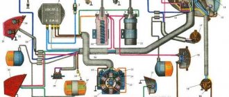
Factory wiring diagram for Java 350 model 1976
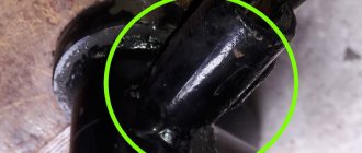
BSZ (Contactless Ignition System) on Java 638
After purchasing and using the Java bike for the first week, I felt that the Java was a beast (my first motorcycle), but almost immediately the problems began after the previous owner, the spark plugs died, or the boiler did not work. I read day and night about BSZ, because I was tired of the contacts, especially since it was time to change them because in 20 years the entire ignition system had worn out. Well, the other day I met Yavist in our town and he had a BSZ. I decided to install it for myself. First I had to buy a Switch from VAZ 2108 – 250 rubles. Hall sensor VAZ 2105-2108 – 95 rubles. Bundle of wires for BSZ from VAZ 2105 – 100 rubles. 2-output coil – GAZ 406 engine (Gazelle, Oka) from 300 to 550 rub And so, everything is there, let's get started 1. Cut out the modulator from the alloy (for starters, you can use steel (iron), for long-term use brass is better). There are 2 types of modulators for BSZ
The plate can be set for the first time (I’ll explain why later), but almost everyone leaves it as the main one. When using this modulator on a perfectly warmed-up engine of the YAVA 638 bike, twitching begins (3-4 jerks when accelerating from low speeds in high gear)
with such a modulator there are 2 options, depending on the driving style, either it rushes like a tank (not bad behavior at the bottom, the dynamics of the Amica, the speed is lower), or it flies like an airplane (that is, the behavior at the bottom is not very good, at high speeds it’s excellent)
Naturally, you can install a modulator from a VAZ (CUP), but few install it.
After we have cut out the modulator, we prepare a platform for the DH (HALL Sensor). If it is possible and you don’t want to waste time, you can try to select a certain number of washers so that the modulator passes through the DH and does not touch it either from above or from below.
Before installing the modulator and DC, it is necessary to remove everything from the pad on the generator (cams, pads, pull out the pin for the cam because it will interfere with the rotation of the modulator.
to install the BSZ there must be an empty surface on the generator. Almost everyone installs the DH on 2 bolts on the lower left side of the generator, which is true, for proper installation we remove the platform on which the cams were attached, etc. and drill a hole with a diameter of 4 under the DH so that the DH It fits perfectly on them, but the bolt must go in (screw in (cut thread 5) so as not to touch anything inside the generator.
We place the modulator on the central bolt of the generator, the DH on 2 bolts, now we can create ignition control using 2 methods - by turning the platform or by turning the modulator.
Now we’re sorting out the wiring.. There won’t be any problems connecting the bundle of wires, there should be 3 more wires left on it, we put the black one on MASS, connect the gray-red one to the blue one (which was connected to both reels earlier) and shove it into the bobbin, making a preliminary connection on the MAMA wire ,The second wire is also inserted into the reel.
We insert the Key, start it, it won’t start))) this is normal, we remove one high voltage, put a foreign spark plug on it (to be sure), and now actually why it won’t start, you don’t need to be scared, it’s normal, you just need to swap the wires on the Brushes, everything is ready , start it up, let it run on one cylinder, turn it off later, remove the cap from another spark plug, put it on a foreign one, and put the one that was hanging on the cylinder that was previously turned off, start it up. let it work a little, turn it off, put both caps on the space, literally adjust the ignition and rejoice
WHAT YOU CAN'T DO NOW:
If you pull off the high-voltage switches while the motor is running, they will immediately break through.
I would like to install the same system on my Java, the spare parts have now arrived, I will install it! Maybe someone who installed it can share their experience!
Source: www.mopedist.ru
Advantages of BSZ relative to KSZ
When writing the article, I sat and thought and thought, and still did not come to a conclusion about what exactly is the main advantage of BSZ; for me, all the advantages listed below are the main ones and are equal to each other.
– Highest stability of the engine (synchronous operation of the cylinders, right in turn)
– Quick response to the throttle
– The best motor thrust (which allows you to easily use the largest drive stars without difficult acceleration!)
– Candles “live” four times longer than at KSZ (I’ll write about this separately below)
– Less recognizable “snot” from Java mufflers (because fuel and oil are burned much better)
– Longer service life of all crank bearings (because there is less third-party detonation and vibration)
– Less fuel consumption (because it burns out better, the carburetor needs to be adjusted to the lowest fuel supply)
Types of BSZ
There are two types of BSZ:
– Single-channel (one Hall sensor, two-lobe modulator, one switch, one two-terminal ignition coil operating on two cylinders at once)
– Two-channel (two Hall sensors, one, or better yet two, modulator lobe, two switches, two ignition coils, one working on each cylinder)
It is better to install a specifically single-channel system, because it will be more stable, because here you do not have to adjust any cylinder (which you have to do at the KSZ), here, if the modulator is manufactured correctly, then only one cylinder is adjusted. Also, in a single-channel one, fewer wires are used, its parts take up less space, and energy consumption is lower (which is very important for 6-volt generators)
There are many people who like to “get confused” who install a two-channel one, shouting at the same time that this way they can configure it more precisely, etc. I assure you that these are unnecessary hassles, and there will be no accuracy here (which is why it is stated above)
Spark plugs. I said above that spark plugs “live” longer, which begs the question “Why?”
Essentially the answer is simple. If you decide to install a single-channel BSZ (or a two-channel one with a two-lobe modulator), then this is what will happen:
When igniting in one cylinder, in the other, with all this, a spark will also strike at BDC, because it strikes on both spark plugs at once, in other words, spark twice per revolution on each spark plug.
What does this give? This allows for warming up and cleaning of the spark plugs at that moment the pistons are at bottom dead center, we get the smallest temperature difference of the spark plug electrodes (not allowing it to cool) and clean electrodes, ready for the new ignition of the fuel mixture. These reasons, as practice has shown, increase the service life of candles.
INSTALLATION OF BSZ
To do this, you need to prepare the following in advance:
– tools: screwdrivers, pliers, hammer, anvil, multimeter (preferably electric), a narrow ruler (up to 10mm wide) or calipers, ratfile and needle files
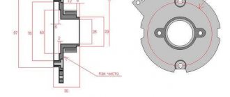
– parts: switch (VAZ-2108), Hall sensor, connecting wiring harness for them (ready-made for sale), two-terminal ignition coil from Gazelle or Oka, modulator (butterfly is made of a magnetic alloy 0.7-1 mm wide according to the drawing below) high-voltage wires (armored wires) of the highest power (preferably silicone)
1.Initial stage
First, let's make a modulator if you haven't already made one. The easiest way to create this is to print out the drawing in real size (the dimensions of the drawing correspond to real measurements), glue the printout onto an iron plate and cut out a modulator along the contours of the drawing. ATTENTION. Accuracy down to mm is key here! So it is not permissible to allow any “in-your-face” behavior here. The edges of the modulator need to be processed with a needle file so that there are no nicks or burrs.
2.Dismantling
– Disconnect the high-voltage wires from the spark plugs.
– Disconnect the inductor wires from the ignition coils
– Remove the ignition coils along with the high-voltage wires (we will no longer need this)
– Disconnect the capacitors from the breaker contacts
– Disconnect the inductor wires from the breaker contacts
– Remove the contacts from the ignition plate
– Remove all screws from the ignition plate and remove it from the generator
3.Preparation
– Place the anvil on a level surface
– Place the ignition plate on the anvil and smooth out all the creases with a hammer, and remove the breaker pins with pliers
– Remove the generator rotor bolt
4.Installation
– Hang the 2-pin ignition coil in a convenient place under the tank
– Connect wires 1 and 4 of the switch to the coil as shown in the diagram, also high-voltage wires to the spark plugs (ATTENTION: DO NOT USE HIGH-VOLTAGE WIRES FROM YOUR OLD COILS. FOR ELECTRONIC IGNITION YOU NEED POWERFUL WIRES, PREFERABLY SILICONE, Sold AVAILABLE IN ANY CAR STORE! )
– Screw the modulator to the rotor with a regular armature bolt
– Attach the Hall sensor to the plate as shown in the photo
– Mount the switch in a place that is comfortable for you (it is recommended to install it on the right cover of the air cleaner directly under the facing cover)
– Lay the connecting wires of the switch and the DC and connect to the switch and the DC
– Ground wire 2 of the switch to the bike frame (do not ground to the tank!)
5.Adjusting the ignition timing (IPA)
5.1. Set the left piston to top dead center, and using a ruler (or caliper) move the piston back 3mm
5.2. Loosen the generator bolt securing the modulator (ATTENTION DO NOT ALLOW THE SMALLEST ROLL OF THE CRANKSHAFT.)
5.3. Connect the multimeter like this: the reddish clamp to the greenish wire of the hall sensor (at the input to the sensor from the greenish wire you need to move the snow-white heat shrink and gain access to the exposed wire), and power the dark clamp of the multimeter to ground (for example, to the engine crankcase)
5.4. Set the multimeter to voltage reading mode in the range of 0-20 volts
5.5. Turn on the ignition (the multimeter should show a value either equal to or close to zero)
5.6. Very slowly turn the modulator so that its alloy enters the Hall sensor while doing this, do not take your eyes off the multimeter!
5.7. As soon as a reading of 4-12 volts appears on the multimeter, stop rotating the modulator, and turn it even more slowly in the opposite direction so that the device just shows zero again!
5.8. Tighten the alternator bolt WITHOUT TURNING THE MODULATOR AND CRANKSHAFT!
5.9. Again, check the position of the piston and double-check the position of the modulator and the readings in this position of the device when tightened; if the readings deviate, then adjust by loosening the screws securing the plate with the DC and slowly rotate the entire plate until the readings become correct.
5.10. Check the readings for the right piston, only if the readings differ, do not move anything from its place (neither the plate nor the modulator), but use a file to sharpen the edge of the modulator that enters the Hall sensor at this moment.
6.Start
– If your bike has a float suppressor on the carburetor, then press it and hold it until fuel starts to drip from the carburetor, but if your motorcycle does not have a float suppressor, but has a cool start mechanism (for example, a Mikuni or Jikov carburetor as on Java 638), then lift flag and pump up three or four times using kickstarter.
– Insert the key into the “ignition” position and sharply pull the kickstarter
If you have the Internet at normal speed, then take a look at our three videos on BSZ to make it more clear how all this is done, including on a bike with 6-volt electrical equipment!
Source: extreme.newline.by
Thanks to the introduction of a 12 V power supply system with a 14 V 15 A generator (i.e. 210 W) on the Java-638 motorcycle, its power is sufficient not only to cover the electricity needs of all consumers on the motorcycle, including the trailed stroller, but also Also, its power reserve allows you to power other consumers, for example, an additional fog lamp, etc.
All elements of the power supply system are manufactured using modern technology and achieve high power and reliability. To prevent damage to them, Java-638 motorcycles should be operated only with a securely connected battery, which cannot be disconnected from the motorcycle’s electrical network while the engine is running. The battery, permanently connected to the synchronous generator (via the “+B” terminal of the rectifier), with its capacity absorbs all voltage peaks that occur in the secondary stator circuit, which in size can be many times greater than the maximum permissible blocking voltage of semiconductor elements and damage them. These voltage peaks occur on the same principle as engine ignition - a spark created by the energy of the spark plug. Under the load of the generator, electric current flows through the coils of the stator winding. As a result of its sharp decrease (by turning off some of the consumers) or even complete cessation (disconnecting the battery if the consumers are turned off), the energy of the electromagnetic field of the coil causes a voltage in the coil by reverse induction, the size of which is directly proportional to the rate of decrease or attenuation of the current and its size. If electric arc welding will be performed on the motorcycle (various types of repairs, improvements, etc.), then before this all wires from the regulator and rectifier should be disconnected.
The following fundamental recommendation regarding the selection of the maximum current of the generator is 15 A. This power can be selected according to the technical conditions of the generator, provided that the temperature of the stator winding does not exceed 155°C. In practice, this means that for a Java-638 motorcycle, including a trailed sidecar, for which a continuous generator power of 12 A is quite sufficient for permanently or temporarily switched on consumers, it is possible to connect another consumer with a power of up to 42 W (i.e. 3 A) for a long time maximum ambient temperature 30-40°C. When using the maximum generator output of 15 A at higher - tropical temperatures exceeding 40 ° C, thermal damage to the stator winding or the insulation of connected wires and connections may occur, particularly when the motorcycle is running at low engine speed and the generator is operating at low engine speeds. characteristic (see Fig. 1) does not yet develop full power.
Rice. 1. Characteristics of a generator with a rectifier in a heated state at an ambient temperature of +20°C
Now let’s look in more detail at the individual elements of the 12 V power supply system. The generator used on the YAVA-638 motorcycle is a three-phase synchronous generator with independent excitation from the battery (i.e., with a six-diode circuit) and a separate rectifier. It consists of a rotor and a stator, and the way it works is similar to how car alternators work.
Rice. 2. Three-phase generator 12 V motorcycle Java-638. The arrow shows the direction of rotation
The rotor is a rotating electromagnet formed by an excitation winding (connected by its contacts to two slip rings), which is wound on a magnetic mild steel core - the core simultaneously represents the rotor axis. It is equipped with an internal cone with a cutout to fit onto the crankshaft. At the other end of the core, in a cylindrical hole, an ignition interrupter cam is installed, the same as that of the generator. The field winding, compressed on both sides between the star-shaped frontal surfaces of the rotor, is impregnated with polyester resin. The magnetic flux generated by the passage of current through the field winding passes through the air gaps between the individual protrusions of the opposite frontal surfaces of the rotor in such a way that its lines of force extend beyond the perimeter of the rotor and, therefore, pass through the stator sheet steel. When the excited rotor rotates, its magnetic field crosses the perpendicular wires of the stator windings, in which an electric current is thus generated by electromagnetic induction. This arrangement of the field winding and the secondary (stator) winding, such as the generator has, produces an electric current with a much higher efficiency already at a lower speed than that of the old 6 V generator - 10.7 A. Therefore, the generator can develop a much higher power than a similarly sized DC generator. The recharging start speed is also lower than that of a DC generator, which allows you to recharge the battery already at engine idle speed when the motorcycle is moving without the headlights on.
The generator stator is a bundle of welded sheet steel with grooves on the inner perimeter in which insulated coils of a three-phase operating winding are installed. The windings of all three phases at one end are combined into a common unit (the so-called star connection), which is output to terminal “86” of the four-pole terminal block and its voltage is controlled by the recharge signal lamp relay. The opposite ends of the windings of the individual phases are individually connected to the “X”, “Y”, “Z” terminals of the four-pole terminal block located in the upper part of the stator casing (when looking towards the generator installed on the engine).
The stator housing is a high-pressure precision casting of aluminum; The stator is hot pressed into the casing. In the middle of the stator casing there is a main breaker board, which differs from the breaker board on the YAVA-634 DC generator only in the size of the 6.3 flat plugs and the longer length of the wires of the connected capacitors. On the right side of the stator casing there is a brush holder made of plastic that is resistant to elevated temperatures. It contains two brushes, pressed by springs to the rotor slip rings; Copper Litz wires connect the individual brushes to the external connection terminals in the form of a 6.3 flat plug, marked "DF" and "I" (ground). The holder with brushes is designed to supply excitation current to the rotor. This is practically the only component of a synchronous generator that is recommended to be checked after a run of about 10 thousand km, namely the degree of wear of the brushes and the possibility of their free movement in the holder. For ease of control of the brushes, a cutout is provided on the side of the stator casing, which allows, after unscrewing the mounting bolts, the holder with brushes to be pulled out of the generator without the need to remove the breaker board and thereby cancel the fine adjustment of the ignition timing. When subsequently installing holders with brushes on a synchronous generator, it is recommended to use the holes in the lower part of the holder under the wire fuse. By first inserting the brushes into the holder and threading a wire approximately 50 mm long through the holes, it is easier to install the holder with brushes and prevents the possibility of breaking the brushes, which otherwise could get stuck behind the edge of the slip rings and break when the holder is pulled to the generator casing. When installing the holder with brushes fixed in this way, thread the wire protruding at the bottom through a suitable hole in the breaker board. After tightening the brush holder bolts, do not forget to remove the wire, since the wire remaining in the brush holder can cause a short circuit on the brushes and damage to the expensive semiconductor regulator when the ignition is turned on (and therefore also the excitation circuit).
The synchronous generator does not require any other monitoring and maintenance. It is only necessary to adjust and lubricate the breaker board in the manner described in the motorcycle maintenance instructions. Therefore, maintenance comes down to only periodic monitoring of the connector connections (no loosening or corrosion). This is the only monitoring and maintenance operation rectifier, semiconductor regulator and relay for the recharge warning light.
The rectifier converts the alternating voltage of all three phases of the synchronous generator into direct voltage. Its basis is a three-phase rectifier bridge, characterized by high rectification efficiency and minimal output voltage ripple
Rice. 3. Connection diagram for generator and rectifier
Rice. 4. Rectifier with designation of connecting terminals made with flat plugs
Due to the fact that it was impossible to place the diodes directly on the stator casing, as is usual on synchronous generators in cars, due to the significant temperatures of the generator without the possibility of cooling by flowing air, as well as due to the vibrations occurring on the engine and the lack of space under the right engine cover, The rectifier is located separately in a box under the saddle. The rectifier is cooled by air flowing into the intake pipe of the intake silencer, near which the rectifier is located, and by air entering under the right cover of the box under the saddle while the motorcycle is moving.
For the rectifier on the YAVA-638 motorcycle, a conventional automobile rectifier bridge is used, from which a direct current of 60 A can be taken with intensive cooling by air supplied from the fan included in each automobile synchronous generator. Due to the fact that the motorcycle does not have such intensive cooling, you can select a maximum direct current of 15 A from this bridge in order to avoid overheating and damage to the diodes - the maximum power of the synchronous generator corresponds to this permissible current.
The rectifier bridge used is manufactured using the most modern technology. So-called tablet diodes are soldered to nickel-plated aluminum profiles - coolers - in a hydrogen electric furnace with one of their electrodes - a cathode or anode, depending on whether the cooler is “plus” or “minus”. A nickel-plated copper strip is soldered to the second electrode of the diode. After assembling both coolers with an insulating insert, these strips are connected by solder at two opposite diodes. Silicon junction pellet diodes can be loaded at high currents and temperatures for short periods of time. The rectifier bridge is mounted in a cover made of sheet material of the rectifier with insulated “PLUS” and “MINUS” pins; on the “MINUS” pin of the rectifier, designated “-I” (grounding). The connections of opposite diodes are connected to the four-pole terminal block by short wires to the terminals “X”, “Y”, “Z”, and to the terminal “+B” - the “+” pole of the rectifier. In this way, the rectifier is connected to the phases of the synchronous generator using the motorcycle wiring harness. The sequence of mutual connection of terminals “X”, “Y”, “Z” on the generator and rectifier does not matter (this means that, for example, you can connect the generator terminal “Y” to the rectifier terminal “X”, etc.).
The semiconductor regulator maintains the DC voltage at the output of the synchronous generator, i.e. at the “+V” terminal of the rectifier, at a constant value of 14 V with a tolerance of +0.3 V - 0.6 V.
Rice. 5. Semiconductor regulator with designation of connected terminals
Its work is to change the value of the average value of the excitation current passing through the generator rotor, in instantaneous, precise dependence on changes in the output voltage of the synchronous generator. This voltage is supplied from the “+B” terminal of the rectifier through the ignition switch to the input of the regulator, i.e. to the “+D” terminal, located in a four-pole terminal block with flat plugs, similar to the rectifier. The output terminal of the regulator “DF” is directly connected to the “DF” terminal on the brush holder of the synchronous generator, the “minus” end of the field winding is grounded, so that the generator excitation operates with the so-called. positive regulation. The “+B” terminal of the regulator must be perfectly connected to the “minus” pole of the synchronous generator, battery and frame (ground) of the motorcycle. For safe operation and shielding of the regulator, the regulator casing is also shorted to ground. The remaining terminal of the regulator “54” in the case of our synchronous generator is not connected; it is intended to signal the recharging of a self-excited synchronous generator, i.e. with a nine-diode circuit (usually used on SKODA passenger cars). To ensure constant regulated voltage at different temperatures, the regulator is equipped with compensation circuits, as well as protective elements to increase operational reliability.
The recharge warning lamp relay is a conventional mechanical relay with NC. contacts - its connection to the terminals is visible in the figure.
Rice. 7. Appearance of the electromagnetic relay of the recharge warning lamp
Rice. 8. Diagram of the electromagnetic relay for the recharge warning lamp
Attraction of the armature (opening of contacts) occurs when the DC voltage on the control winding (terminal “86”) is within the range of 4.8 - 8.6 V; this voltage value, taken from the center of the stator winding of the synchronous generator, corresponds to the correct function of all three phases. In the event of a malfunction or complete failure in the operation of one phase, a change in this voltage occurs, which will immediately be manifested by a constant or intermittent light of the warning lamp. Whenever manipulating the relay, it is necessary to ensure that the plastic relay cap is properly seated so that the relay contacts do not become dirty during operation of the motorcycle.
Installation of BSZ on Jawa-638
I apologize for the repost, this article is lying around in bundles on the internet, but when I need it I can’t always find it in the usual version with all the pictures, and at the moment I’m just installing BSZ on my own Boberly RX1, so I decided to post it on the blog so that was always at hand.
Installation of BSZ on a Java-638 generator
STEALING I saddled my first Jawa ten years ago and since that time I have remained an admirer of Czech technology. But in recent years, the increased need to constantly find spare parts has shaken my attachment. Well, their property became simply “none.”
Including the ignition system breaker. It is crammed with nothing but troubles: either the contacts burn up “in smoke” within a few miles of driving, then for some unknown reason the painstakingly adjusted gaps “float away” from the required dimensions in a couple of days, the spark plug spark gaps are covered with “the devil” and completely refuse to spark. With such a “lighter”, driving turns into fidgeting and endless repairs. Add to this a battery that has dropped by two or three volts, and with it, starting a cool engine turns into torture.
RUSSELLING The publication in Moto (N9-2001) about the non-contact ignition system (BSI) of Jupiter-5 helped free the ignition from defects: installing a similar circuit turned out to be a matter of just one day. The only “author’s” part, invented by me, is the supporting platform of the Hall sensor, and that one was borrowed from the bearing of the vacuum corrector of the “Volgov” ignition distributor.
Contactless ignition system: 1 - battery; 2 — ignition switch; 3 — spark plugs; 4 - two-terminal ignition coil; 5 - voltmeter; 6 - switch; 7 - Hall sensor.
The performance of the Jawa engine equipped with BSZ has become completely different and, I would add, pleasant to the pilot. The sound of the engine has acquired the required softness; at idle speed it simply rustles. The “steel” notes inherent in the occurrence of glow ignition and detonation have completely disappeared. The bike obeys the throttle perfectly and responds to the opening of the throttle with a quick increase in speed. The engine starts smoothly even with a quarter-discharged battery.
But the circuit seemed overloaded to me: I think two stripes “sensor - switch - coil” are unnecessary. I simplified the BSZ. “Double” parts become unnecessary when using a two-terminal coil and a symmetrical shutter modulator. In my circuit, the coil discharges to both spark plugs at once. In one of the cylinders, the spark coincides with the intake-compression stroke and ignites the working mixture, in the other it occurs during the working stroke - exhaust and is wasted. But a massive “electrical” discharge is more than enough for both cylinders. By the way, ignition components have become half cheaper: from 680 to 350 rubles.
What to do next?
Most likely, the ignition you assembled from a Java 634 scooter is rough and consists of twists, which is why you should replace them with normal terminals and twist the wires into braids. There is only a small matter left to do - completely replace all the remaining electrical elements, starting from the dashboard and ending with the head lighting and turn signals. Fortunately, now you have full 12 volts, so you can replace everything with spare parts from older models. On the other hand, 12 volts open up the opportunity to install almost any modern turn signal, high-quality lighting and many other useful devices such as a charger for a smartphone or an on-board audio system.
BSZ to Java 638
Ded140 Senior Member Topic creator
| 8 years on the website user #451748 I understand that the topic has already been heard 100 times and they will send me to Google, but I’m asking KNOWLEDGEABLE guys to explain what’s what. I ask you to write a list of what exactly is needed (preferably with a photo and, if possible, with photographs), but the more thorough the better. Effort is not enough to achieve the goal. Naumbl4 Senior Member |
| 9 years on the website user #311284 . uh in Java ru, everything is chewed up izerli Senior Member |
| 9 years on the website user #315974 Ded140 , which specific BSZ? From Zhigov's tsatsek or the Minsk gene? I put it together according to the scheme from Zhigov’s tsatseks into a motorcycle and nothing works for me, although it works for others. Skomoroh Senior Member |
| 14 years on the website user #36696 izerli , I still forgot the optical one. izerli Senior Member |
| 9 years on the website user #315974 Skomoroh , Oh yes. feet in my mouth. Naumbl4 Senior Member |
| 9 years on the website user #311284 when Java was collected from Zhigava trants, it worked on it and others like it, and it seems like 6 in Java izerli Senior Member |
| 9 years on the website user #315974 But still the branch lives. Cams, capacitors are a thing of the past! And now it's not high quality. Well done Ded140 , constructive! Naumbl4 Senior Member |
| 9 years on the website user #311284 Yes, how I remember the micrometer at the moment, the fists that were playing around...ooohhh izerli Senior Member |
| 9 years on the website user #315974 or capacitors - xs. some are normal and some are not. Skomoroh Senior Member |
14 years on the website user #36696
In Java it was made from Lada parts, because... It was impossible to find high-quality cams even then. On the boxer, where high-quality cams were obtained, the cam worked unsurpassed. So it's not a matter of design. Ded140 , there is such a person - Roma Fakn Mad, on the L_R onliner. Contact him, he can create a BSZ for money. Ded140 Senior Member Topic creator |
| 8 years on the website user #451748 I think something from the Russian “Magic of Automotive Equipment”. I am interested in a certain model of equipment, certain sizes of records and all that, even better with the prices for these products. Java 638. I will assemble the BSZ myself, but I don’t understand or understand anything. explain everything as thoroughly as possible plz)) and so that everything is CHEAPER. I understand sarcasm.. but plz))) Effort is not enough to achieve the goal. izerli Senior Member |
| 9 years on the website user #315974 Ded140 , coil for electric ignition from Volga, switch, Hall sensor, harness. The prices at the moment are bad, I don’t understand them clearly. skif1905 Senior Member |
| 10 years on the website user #191690 So find someone to do this for you. Or buy a book on the theory of the internal combustion engine, read it and then we’ll talk further. Ded140 Senior Member Topic creator |
| 8 years on the website user #451748 You will need to purchase: 1. a two-channel ignition coil (Oka car), 2. a switch from VAZ (*.3734), 3. create a curtain modulator (according to the dimensions of the OP already installed on the generator) 4. and a set of wires ( This is not for everybody, you can make do with your own) 1. two-channel ignition coil (Oka car), 1.1. ignition coil from VAZ 2108 for example 27.3705 2. switch from VAZ (*.3734), 2. 1. switch from VAZ 2108 for example 76.3734 or 0529.3734 or some other. 3. 4. connecting wires for BSZ from VAZ without EPHH for example like this. I compiled it from a search engine. - correct me if something is wrong Effort is not enough to achieve the goal. Wofka Bolt Member |
| 11 years on the website user #154614 For a fee, I’ll install and set it up! I’ll select high-quality components! I will also convert the 6V Java to 12V General IZH. Ded140 Senior Member Topic creator |
| 8 years on the website user #451748 You will need to purchase: 1. a two-channel ignition coil (Oka car), 2. a switch from VAZ (*.3734), 3. create a curtain modulator (according to the dimensions of the OP already installed on the generator) 4. and a set of wires ( This is not for everybody, you can make do with your own) 1. two-channel ignition coil (Oka car), 1.1. ignition coil from VAZ 2108 for example 27.3705 2. switch from VAZ (*.3734), 2. 1. switch from VAZ 2108 for example 76.3734 or 0529.3734 or some other. 3. 4. connecting wires for BSZ from VAZ without EPHH for example like this. I compiled it from a search engine. - correct me if something is wrong For a fee, I’ll install and set it up! I’ll select high-quality components! I will also convert the 6V Java to 12V General IZH. I have a faceplate for transition to 12V equipment from Java 638. I forgot to add, OP and FUOZ will do it for me. (I am making a FUOZ board (as in the picture) - 150 thousand and an opto-sensor (OP) - 50 thousand) Source: forum.onliner.by |
What will you need?
To install the ignition from a scooter in Java, we will need a specific conversion kit. First of all, there is the generator itself; there are two models to choose from. The simpler QMB-139 will perform all the necessary functions, but problems may arise with the light at night, since the winding for the head light is rather weak and will greatly depend on the speed. If this parameter is important to you, then choose a stator from the QMI-157 or 152QMI model - they will be sufficient to achieve your goals.
You will also need an ignition coil with two terminals, here again there is plenty to choose from. For our purposes, motor coils ZMZ-406 or from Oka are suitable.
You will need a 12 volt battery. We don't need a new one; any used motorcycle or new Chinese battery will do. Its role is to smooth out voltage drops in the turn signal and stop signal circuits.
Also, do not forget about the set of wires/terminals. It is better to take the latter from Japanese scooters.
The last item is the adapter plate. Alas, it cannot be found on sale, but kind people have prepared the exact drawings presented below, according to which you can assemble your own adapter plate or order it. The thickness of the metal is 4 mm, this is an important parameter, because if you make the plate larger or smaller, some elements of the system may not fit or work incorrectly.
To watch online, click on the video ⤵
inexpensive BSZ set for Java (Jawa, Cezeta 501) More details
INSTALLED BSZ on Java 638 (634) 350. More details
Installation of the SoveK LLC Contactless Ignition System on a YAVA bike. Part 1. Read more
CONTACTLESS IGNITION SYSTEM for Java 638 (634) 350. More details
BSZ INSTALLATION JAWA JAVA 350 638 634 IZH ELECTRONIC IGNITION SYSTEM Read more
Installation and adjustment of BSZ Saruman on a Jawa 350 638 bike Read more
Java electric ignition setting 634-638 (BZS) Java 350 Read more
Installation of the SoveK LLC Contactless Ignition System on a YAVA bike. Part 2. Read more
installation of ignition with a hall sensor on a bike. BASHKIRIA STERLITAMAK Read more
Overview of the BSZ Jawa 638 installation Read more
electric ignition in reality 350 638 More details
adjustment and repair of motorcycle JAWA 638 Java (electric ignition. carburetor) Read more
contactless ignition IZH Jupiter 5 Read more
How is BSZ better than contact ignition? Read more
It can't be! It is so simple! Checking the Hall Sensor. More details
Setting the ignition in Java with free Read more
Java errors according to BSZ Read more
BSZ with variable OZ for 634 engine with 12V generator. More details
INDEPENDENT PRODUCTION OF IZH PLANET MOTORCYCLE IGNITION SYSTEM MODULATOR Read more
Source: putinizm.ru
Features of the package
The motorcycle was supplied to the USSR in several modifications:
- “JAWA 250” model 559-07 - option with 6V equipment and a 250 cc engine with 12 hp. Produced since 1969;
- “JAWA 350” model 634-04 - option with 6V equipment and a 350 cc engine with 16 hp. Produced since 1973;
- "JAWA 350" model 634-08 - version with 12V equipment on 16-inch wheels. Produced since 1977;
- “JAWA 350” model 638 is the last of the models supplied to the USSR. It was produced since 1986 and was distinguished by wheels increased to 18 inches and a different frame shape.
The price of a used Java was 2 times higher than the price of a new domestic motorcycle
Power supplies for electrical equipment
A special feature of the Czech motorcycle was a generator, which made it possible to operate the Java without a battery. Its design included a method of exciting an electric current sufficient to supply a spark when the engine starts.
Factory black and white instructions - main generator components
In the diagram presented, the numbers indicate:
- JAWA generator stator;
- breaker lever;
- electronic voltage regulator;
- relay-regulator panel 4-terminal;
- capacitors 2 pcs. - for each cylinder.
For reference: the generator was a system of insulated radial lamellas. Inside the stator there were coils and a rotating rotor with a winding. During the rotation process, a magnetic field was formed in the excitation winding, and the alternating current was converted into direct current through an electronic converter.
Accumulator battery
Along with the new motorcycle, a 14 Amp-hour alkaline battery was included.
Its peculiarity was that:
- The battery was supplied in a dry charged state;
- Before operation, it was required to fill it with electrolyte;
- It was recommended to charge the battery for 5-6 hours before starting work.
In practice, everything happened differently:
- The happy owner brought ready-made electrolyte with him to the store;
- I filled the battery containers with it;
- ;
- Exploited (drove home).
For reference: the additional battery charge recommended by the manufacturer is needed to ensure that the lead plates are saturated with electrolyte under the influence of electric current. Thanks to this, the battery life increased to 4-5 years, while violation of this recommendation shortened the service life to 1-2 years.