Moto Dnepr gearbox repair
REPAIR OF GEARBOX OF MOTORCYCLES “DNEPR” AND “URAL”
Dismantling.
Most often, the need to repair the gearbox is determined while the motorcycle is moving: by the strong noise of the gear wheels, jerking in the transmission, and self-disengaging gears. In each case of repair, the gearbox is disassembled only to the required extent. Before disassembling, drain the oil from it (preferably when it is still warm), pour in 1 liter of kerosene, turn the box shafts and then drain it.
The 6204 gearbox mechanism is assembled in a cast one-piece housing with three removable covers: the front one, which serves as a support for the bearings, and two side ones - right and left. The main parts of the gearbox (section along the shafts) are shown in Figure 48.
The gearbox is disassembled in the following order: remove the clutch release lever, press the front end of the clutch release rod 6 and remove the clutch release slide 15 with the thrust bearing and rod tip and the clutch release rod. Unscrew the speedometer drive bushing bolt and remove the thrust bushing. Rotating the driven shaft counterclockwise (as viewed from the side of the elastic coupling disk), remove the driven gear of the speedometer drive 13. Unscrew the castle nut 14 of the driven shaft, remove the cotter pin, unscrew the nut, remove the washer and drive disk of the flexible coupling of the cardan shaft.
The gearbox shift mechanism is shown in Figure 49. To remove the left cover assembly with the foot shift mechanism, you need to unscrew the bolts. After unscrewing the nut, remove the crank lever and the shift pawl. Remove the ratchet along with the crank from the cover socket. Remove the retaining ring from the ratchet hub. Unscrew the screw securing the right cover and remove it as an assembly with the sector and manual shift levers, remove the cover gasket. Unscrew the nut, remove the washer and knock out the wedge. Remove the lever. Unscrew the shaft stopper of 4 gearshift forks in the rear wall of the gearbox housing and, lowering the screws, knock out the shaft from the front wall of the housing and remove the shift forks.
The details of the trigger mechanism, shafts and gears of the gearbox are shown in Figure 50. To remove the lever 20 of the trigger mechanism, unscrew the nut, remove the washer and knock out the wedge bolt. Unscrew the trigger shaft buffer plug and remove the spring, and then the buffer pin (not shown in the figure).
Unscrew the screws securing the front bushing of the trigger shaft and remove the bushing. When unscrewing the second screw, the bushing is kept from rotating. Unscrew the screws securing the rear shaft bushing oil seal, remove the washer, oil seal, and rear bushing.
Unscrew the bolts securing the front crankcase cover. With light blows of an aluminum hammer on the end of the driven shaft and through a mandrel on the end of the drive shaft, the shafts are pressed out of the gear housing along with the front cover. Unscrew the screws securing the flange of the front bearing cover of the driven shaft, remove the flange, cover washer and adjusting washers. Press the drive and driven shafts and driven shaft bearings out of the front cover.
If necessary, completely disassemble the drive and driven shafts using the device shown in Figure 51. To press the ball bearing 304 from the driven shaft of the gearbox (Fig. 51.6) from the specified set of auxiliary parts
use: support bar 5, mandrel 6 and support washer 7. To press out the roller bearing from the drive shaft, use support bar 5, mandrel 9 and washer 12 (Fig. 51,c). When pressing out the fourth gear gear, ball bearing and oil release clutch from the drive shaft, use a support bar 5, a sleeve 8 and a mandrel 9. The auxiliary parts shown in Figure 51, c, fully ensure the disassembly and assembly of the gearbox shafts.
A section of the MT-804 gearbox (section along the shafts) is shown in Figure 52. All parts of the box are installed in a cast crankcase. The crankcase is closed at the back with a lid. At the front, the crankcase has a flange that secures it to the engine crankcase using three studs and one bolt. Remove, like the 6204 gearbox, the trigger lever, lever
clutch release, slider, thrust bearing, clutch release rod tip and elastic coupling disc. Unscrew the screws securing the bushing/shaft of the trigger mechanism to the front wall of the crankcase and, having reset the winding of spring 3, unscrew the bolts securing the cover, install the axis of the clutch release lever in its place, and thread a soft cord through it. Holding the cover by the cord, lightly knock out the drive 9 and driven 10 shafts. Remove the cover and gasket.
The reverse gear is removed from the drive shaft, and the reverse gear with the shift fork is removed from the driven shaft. Take out the trigger shaft 5 assembly, remove the spring and gears 33 and 32 of the trigger mechanism and washers from the intermediate shaft 5. Slide the shift fork shaft out of the hole in the crankcase (without removing it from the shift forks); remove the forks with the shaft from the grooves of the shift disk. Place the disc of the elastic coupling 26 on the driven shaft and secure it with a nut. With light blows on the end of the drive shaft and the elastic coupling disk, the shafts with forks are pressed out of the crankcase. Pull back the lever lock and remove the shift disk from the axle.
Figure 53 shows the drive and driven shafts and the trigger mechanism in disassembled form, and Figure 54 shows the parts of the reverse gearbox shift mechanism.
To remove gear shift shaft 5 from the crankcase (see Fig. 54), remove the pawl shaft 16, pawl 17 and spring 14, unscrew and unscrew the nut 19 securing the crank cam 3 and remove it from the shift shaft splines.
Remove pin 29 from the crankcase (Fig. 55), remove the reverse gear lever 17 and remove the reverse gear lever 31 from the crankcase.
Source
content .. 31 32 37 ..MOTORCYCLE GEARBOX “DNEPR”
In models MT9, MT10, MT10-36, (“Dnepr-11”, “Dnepr-12”, “Dnepr-16”), MV-750M MV-650, a two-shaft four-speed gearbox with reverse gear and an automatic clutch release mechanism is installed model MT804 (Fig. 4.11).
The box has been equipped with a reverse gear, a mechanism for power release of the clutch when changing gears, and other components have been changed. The gearbox can be installed on motorcycles of the Kyiv Motorcycle Plant models K-750, K-750M, K-650 and on the latest models of Ural motorcycles. If boxes from previous editions are replaced, some modifications will need to be made. The driveshaft needs to be shortened.
For a shaft designed by the Kyiv Motorcycle Plant, this can be done by rearranging the retaining ring, which is located at the rear end of the propeller shaft. If necessary, cut another groove on the shaft, slightly shortening the cardan fork. The fork and shaft can also be connected with a pin (Fig. 4.12). The shaft is shortened on the cardan joint side by such an amount that the end of the shaft is removed from the oiler by a distance of at least 3 mm.
On motorcycles of the Kyiv Motorcycle Plant models K-750, K-750M, the frame is shorter than on subsequent models, so contact between the spring cardan disc and the frame is possible. In this case, bevels are made on the disk and frame (Fig. 4.13). Unlike the box of previous releases, the neutral of the switching mechanism is set by a foot pedal using a lamp-lamp indicator, which is mounted on the instrument panel. The flashlight switching circuit is shown in Fig. 4.14. Unlike the previous gearbox, the housing consists of a crankcase and one cover. A cardboard gasket is installed between the crankcase and the cover, which is lubricated with grease, for example, Litol-24. The gasket does not stick to metal surfaces and remains on the cover or crankcase during disassembly.
Rice. 4.11. Gearbox of motorcycles "Dnepr": 1 - intermediate shaft; 2 - input shaft; 3 - clutch release rod; 4 — dipstick with breather; 5 - crankcase; 6 - idler gear; 7 — idler gear axis; 8 - gasket; 9- cover; 10 — reverse gear shift handle; 11 — clutch release lever; 12 — elastic coupling disk; 13 - secondary shaft; 14 — adjusting bolt; 15 — drain plug; 16 — shaft with the trigger sector; 17 - gear shift pedal
Rice. 4.12. Reducing the dimensions of the driveshaft
Rice. 4.13. Mating the spring clutch disk and the motorcycle frame: 1 - bevel on the disk. 2 - maximum permissible position of the spring clutch disk. 3 — memorial position of the disk: 4 — bevel on the frame
Rice. 4.14. Switching diagram for the neutral indicator lamp: 1 - neutral indicator lamp; 2 - wire, 3 - insulating cap
Rice. 4.15. Primary shaft and starting mechanism for motorcycles “Dnepr-11/16”: 1 - shaft assembly; 2 - key, 3 - shaft; 4, 5 — gears; 6 — bearing; 7 - ring; 8 - coupling; 9 — washer; 10 - spring, 11 - washer; 12 - ring; 13 — bushing; 14 - screw; 15 - spring; 16 — washer, 17, 18 — gears; 19 — lever assembly, 20 — lever; 21 - roller; 22 — bushing; 23 - wedge bolt; 24 — washer; 25 — nut, 26 — shaft assembly; 27 - shaft; 28 - sector
Rice. 4.16. Secondary shaft of motorcycles "Dnepr-11/16": 1 - shaft assembly; 5, 9, 11, 15, 20, 22, 23, 29 — gears; 2 - key; 3 - shaft; 4, 8, 10, 14 — bushings; 6, 7, 12, 13 — couplings; 16, 19, 26 — washers; 17, 18 — bearing; 21 - bolt; 24 - nut; 25 — cotter pin; 27 — disk; 28 — disk assembly; 30 - ring; 31 - gasket.
SHAFT OF MOTORCYCLE GEARBOX “DNEPR”
The primary shaft is mounted on two bearings. The shaft is made integral with the rims of the reverse gears, first and second gears. The gears of the third and fourth gears are mounted. The fourth gear gear is kept from turning by a slot key. The third gear gear is connected to the fourth gear gear using end lugs.
The secondary shaft is also mounted on two bearings and has a spline for the reverse sliding gear. Two splined couplings are pressed onto the shaft and are held from turning by keys. The gears of the first, second and third gears rotate freely on cermet bushings, and the fourth gear gear rotates freely on a bronze bushing. The gears are connected to the shaft using movable gear clutches. There is no special supply of lubricant to the rubbing surfaces.
Rice. 4.17. Shafts and gear wheels of the gearbox of Ural motorcycles: 1, 20 - oil squeegee washers; 2, 6, 7, 9 — gear wheels of the 4th, 3rd, 2nd and 1st gears of the driven shaft; 3, 5 — driven shaft and its coupling; 4 — engagement clutch, 8, 27 — clutches; 10 — bolt of the speedometer drive bushing; 11, 12 — bushing and gear wheel of the speedometer drive; 13 — cotter pin; 14, 29 — nuts; 15, 28 — washers, 16 — driveshaft coupling disk assembly; 17 — lever wedge bolt; 18 - lever, 19 - bearing; 21 — block of gear wheels of the 3rd, 2nd and 1st gears of the drive shaft; 22 - key; 23 - drive shaft assembly; 24 — gear wheel of the 4th gear of the drive shaft; 25 — bearing; 26 - gasket; 30, 31 — pawl spring and its pin; 32, 33 — pawl and its axis; 34, 36, 38 - shaft, gear and trigger spring; 35 - pin; 37 — bushing
content .. 31 32 37 ..
Messages [1 to 20 of 115]
1↑ Topic by mexanik62 09-10-2011 23:41:16
Topic: Addition to the topic of repair of the Dneprov checkpoint
I took a photo of the key moments (in my opinion) of disassembling and assembling the Dnepr checkpoint
Added: 09-10-2011 16:28:47
Added: 09-10-2011 16:43:22
Loosen the screws of the clamp Place the key while holding the tension of the spring Unscrew the screws, lower the spring and remove the clamp
Added: 09-10-2011 16:45:15
After this, you can disassemble the box with something like this:
Added: 09-10-2011 16:55:27
Added: 09-10-2011 17:13:02
Take everything out of the box Rock this lever The accuracy of gear shifting depends on its position; it is also the automatic clutch drive. If it is loose, loosen the nut and tighten it. If it still hangs, then the splines have already sagged and you need to file the end as in the photo so that the washer will hold.
Added: 09-10-2011 17:27:25
and it should turn out something like this
Added: 09-10-2011 17:38:50
There is no need to grind down too much so that there is a millimeter of reserve
Added: 09-10-2011 17:58:15
Check the forks, bosses without flats, horns 5.7-6 mm thick, grooves in the disk, three bosses on the disk should not wobble, if necessary, rivet the neutral contact
Added: 09-10-2011 18:13:38
Assemble the switching mechanism Install the primary shaft, do not forget the spring washer with teeth inward and towards the bearing, assemble the secondary shaft as in the photo and insert it into the box
Added: 09-10-2011 18:23:40
Assembling the kick shaft for installation
Added: 09-10-2011 18:32:25
Kick groove position
Added: 09-10-2011 18:35:57
I will try to answer questions about the repair and setup of the Dnieper checkpoint
Added: 09-10-2011 19:33:39
Added: 09-10-2011 19:41:16
This is about the difference between the Dnepr gearboxes. At the top, the primary shaft of the MV650 was sometimes installed at 16. They differ in 1st gear, 37:9, i.e. 4.1, more high-torque than 36:10 (3.6) for all other Dneprs. Everything else is the same.
Source
Dnepr motorcycle gearbox repair
Whether your transmission needs repair or not, you will be able to understand when driving your motorcycle. If there is a strong gear noise coming from the unit, the gears switch off automatically or do not engage (non-engagement), or some gear is jammed, jerks or shocks occur in the transmission - this means that repair cannot be avoided. I advise you not to lay out your road tool on the asphalt, but rather to somehow get to your garage, where there is a more reliable tool and a clean table, because there is nowhere to rush.
The first step is to remove your transmission from the motorcycle. To do this, remove the rear wheel, rear axle with driveshaft, disconnect the neutral wire and disconnect the clutch cable. Don't forget to remove the air filter. Before disconnecting the box from the engine and removing it from the motorcycle, I advise you to drain the oil from it by unscrewing the drain plug at the bottom. And before moving your gearbox onto a clean table or workbench, thoroughly wash it from any dirt on the outside. There are plenty of cleaning chemicals on the market now that can make the crankcase of any unit look like new, but Solvent can also be used. A clean gearbox will be much easier and more enjoyable to disassemble.
Photo 1. Details of the kickstarter mechanism. 1 - shaft sleeve, 2 - thrust washer, 3 - return spring, 4 and 5 - ratchet gears, 6 and 7 - thrust washers of ratchet gears, 8 - support spring, 9 - shaft sleeve, 10 - shaft with gear sector, 11 - kickstarter lever.
Place the gearbox on a clean table or workbench and begin disassembly. First of all, reset the kickstarter spring tension. To do this, on the front of the crankcase (where the box is attached to the engine), unscrew the two countersunk screws that secure bushing 1 of the kickstarter spring (photo 1). Then turn the box over with the back cover up (where the rubber cardan coupling is put on) and disconnect clutch lever 5 (photo 2), then remove slider 1 with a rubber ring (I advise you to give the slider to a turner to machine another groove for the second rubber ring, it’s more reliable) . Also remove the thrust bearing 2 and the tip of the clutch rod 3. Next, remove the wedge that holds the kickstarter 11 (photo 2) and remove the kickstarter itself.
Photo 2. Clutch release mechanism. 1 — slider with a rubber sealing ring, 2 — thrust bearing, 3 — tip of the clutch rod, 4 — clutch release rod, 5 — clutch lever.
Photo 3. Rubber coupling fork disc and castle nut.
Remove the cotter pin and unscrew the castle nut of the rubber coupling fork disk, then remove the fork disk itself (photo 3). Now you can use a 10 mm socket to unscrew all the M6 bolts securing the rear gearbox cover. Now, having inserted a metal pin into the hole in the clutch lever axis, lift the box slightly above the table, holding it by this pin, and with light blows of a wooden, plastic or lead mallet, knock out the primary and secondary shafts from the cover. The lid will remain in your hands.
The time has come to wash everything from the inside using Solvent or gasoline and carefully examine all the insides of the gearbox, looking for wear or breakage of parts (photo 4). On the right is the secondary shaft 1, in the top center is the reverse idler gear 3, below it in the center is the primary shaft 4, to the left of it is shaft 5 on which the kickstarter ratchet gears rotate, and below on the left is shaft 6 of the lever with the kickstarter gear sector . Just below and to the right there is a gear shift mechanism 7, which is controlled using gear forks, which are installed on the shaft 8.
Photo 4. Location of shafts and gearbox parts. 1 - secondary shaft with first-fourth gears and reverse gears, 2 - reverse gear, 3 - reverse idler gear, 4 - input shaft with first-fourth gears and reverse gears, 5 - shaft with kickstarter ratchet gears, 6 - kickstarter shaft with a gear sector, 7 - gear shift mechanism, 8 - shaft with gear shift forks.
Subsequent disassembly of the box is simple and removing the shafts will not be difficult, but searching for worn parts will require attention and careful examination of the surfaces of the parts. When removing the shafts, I advise, in order not to confuse the parts, for each shaft with its gears, prepare some kind of container (bath), for example, cut out of a small oil canister. This will help you avoid mistakes and unnecessary movements later during assembly.
To begin, remove the reverse gear 3, and also remove the reverse gear 2 from the secondary shaft along with its shift fork. Remove the kickstarter shaft 6, together with its parts and the ratchet gears with thrust washers and spring 5. Remove the shaft 8 of the gear shift forks, and separate the shift forks themselves from the disc grooves. Next, put the fork disk of the rubber coupling in its place (on the secondary shaft 1) and secure it with a castle nut.
Then, with light blows of a mallet on the fork disk and on the end of the input shaft 4, remove both shafts from the gearbox housing along with the gear shift forks. Press out all the removable gears from the shafts, and also remove all the keys and bushings. When pressing, use pullers or a press, such as the one in this article. And between the press and the gears when pressing out, use spacers made of brass or bronze. The shaft details are shown in detail in photographs 5,6 and 7.
Photo 5. Details of the input shaft. 1,2,3- sealing rings, 4- bearing, 5,6- third and fourth gears, 7- input shaft with cut second, first and reverse gears, 8- key
When you remove the gear shift fork shaft from the gearbox housing, remove the pawl shaft, pawl and spring 3, then pull out the lever lock 1, and then remove the gear shift disk 2 from its axis (photo 8). To unscrew nut 4, remove the cotter pin that secures it, unscrew the nut and then remove the figured crank 3 (photo 9) from the splines of shift shaft 5. All gear shift parts are shown in detail in photo 9.
After disassembling all gearbox mechanisms, thoroughly wash all parts and carefully inspect them. Such noticeable defects as chipping or wear of gear teeth, breakage or wear of the surface (all parts should not have wear steps) of parts are immediately visible and should be replaced. The bearings should not have any play, crunch or jam, but in general I advise you to replace all the bearings with branded ones (read how to choose a bearing here), since recently the Ukrainian bearings that are used to equip the Dnieper boxes at the factory, and the Ural ones too, are of very low quality . The bearings must not rotate in their seat in the crankcase. Replace all seals with new ones, preferably from European companies.
Photo 6. The secondary shaft is almost assembled. 1 - ball bearing, 2 - fourth gear, 3 - fourth and third gear shift clutch, 4 - third gear, 5 - second gear, 6 - second and first gear shift clutch, 7 - first gear, 8 - rear gear gears, 9 - washer, 10 - secondary shaft.
Also, most domestic gearboxes suffer from mismatched teeth of the shaft gears (primary and secondary), that is, the gears seem to be shifted relative to each other and their teeth do not work with the full surface, but only half. You can correct the position by moving the gear on the shaft and placing an adjusting washer.
All gears whose teeth are at least partially worn or chipped should be replaced with new ones. If the teeth are intact, but heavily worn, then the gearbox usually howls loudly, especially under load (when gas is supplied). Only new gears will help get rid of this. A puller will help you pull gears or bearings off the shaft, and an example of a universal puller for most gearboxes.
When purchasing new parts (gears), check their hardness using a needle file (otherwise there is a lot of raw lefty stuff on sale). The needle file should not leave marks on the gear teeth and surfaces of the new shafts. Backlash of shafts and gears is unacceptable. The keys on the shafts should not show wear in the form of a step, and the keys themselves should be inserted tightly into the keyway of the shaft.
The shift forks may be worn at the point of friction, but wear in the form of a step is unacceptable. The same goes for the shift dial. Its pins should not have a development in the form of an oval or ledge (step). The pins of the forks that go along the figured cutouts of the disk should also not be worn out in the form of an oval or step. There should also be no stepped wear on the gearshift couplings or licked spline edges (on gear splines too), since this can cause the engaged gear to fly out, but small abrasions from friction are acceptable.
The gearbox housing and its cover must be connected to each other without distortions, and the planes of their joining must not have nicks, scratches or chips. Scratches and small nicks can be eliminated on a lapping plate, and chips can be restored by argon-arc welding, followed by grinding of the seams. Don't forget to install a new gasket under the box cover. It costs a penny, but it will help avoid oil leaks. I advise you to use a paronite gasket rather than a cardboard one.
Photo 8. Details of the gear shift mechanism. 1 - lever retainer, 2 - gear shift disc, 3 - shaft with pawl and spring, 4 - castle nut, 5 - gear shift shaft with crank cam and return spring.
The gearbox is assembled in the reverse order of disassembly. Before assembly, set the gear shift dial to neutral (put the gear in neutral between first and second). Also, do not forget to turn the kickstarter return spring 3 (in photo 1) 1.5 turns counterclockwise. To do this, you can use a grinder key by inserting it into the screw holes and turning the bushing with it. Then try to hold the bushing in this position, slightly lift one pin of the key, and insert at least one screw, and then the second.
After assembling the box, check that all gears shift easily and without jamming; when shifting, do not forget to rotate the secondary shaft by the rubber coupling. And in general, also check the ease of rotation of the shafts without jamming in all gears. Under the castle nut of the fork disk of the rubber coupling, or rather under the washer of this nut, do not forget to place a new rubber ring, and even lubricate it with sealant. This will prevent oil from flowing along the splines of the secondary shaft.
Photo 9. Gear shift mechanism. 1 - gear shift shaft with pedal, 2 - return spring, 3 - automatic clutch crank cam, 4 - washer, 5 - shaft with pawl, 6 - gear shift disc, 7 - castle nut, 8 - reverse gear fork, 9 - fork for shifting the first and second gears, 10 — fork for shifting the third and fourth gears, 11 — roller for shifting forks.
After repairing the gearbox and installing it on the motorcycle, the gearbox should be run in (especially when replacing most of the parts with new ones). To do this, place your bike on the center stand and start the engine, keep it in first gear for 10 minutes, at an engine speed of approximately 1500 rpm. Then let it run for 10 minutes in second gear at 2000 rpm, and then 5-7 minutes in third gear, and also in fourth, and this at 2000 rpm. Just remember to cool the engine with a household fan, or take breaks after each gear to cool the engine. After the first idle run-in, drain the oil from the box and fill it with fresh oil. All that remains is to run the motorcycle in again, but on the move, adhering to the above-described crankshaft revolutions and time for each gear, and not exceeding them.
When operating a motorcycle, often pay attention to the asphalt under the bike’s engine. If oil leaks appear, it is advisable to eliminate them in a timely manner and monitor the correct oil level in the crankcase. This is important, since most breakdowns or rapid wear of gearbox parts occur due to a decrease in oil level. By following this simple rule, your gearbox will not need repairs for a long time. Good luck everyone!
Source
Dnepr gearbox with accelerated gears. Brief report and my impressions
We look at GOST or the directory of Anuriev’s designer. If the number of teeth is less than 17, an angular correction of the tooth is necessary, otherwise there will either be jamming of the gearing or (if the involute is made correctly on a gear cutter) - undercutting of the tooth stem (the teeth will break off, not strong).
Just look at the M-72 drawings, which are also available on this site. The center line in the Urals and Dnieper is made a little more positive - so that tooth correction can be done for 1st gear (10 teeth gear) and 2nd gear (gear). Probably, after all, the gearbox was designed by the Germans in 1939-1940, and on the M-72, as you know, they stupidly copied it from the Germans. In total, with a slightly increased center distance, the total correction factor is 0.41. The breakdown of the correction coefficient is as follows: on a gear, the correction coefficient is positive and equal to +0.41, and on a 36-teeth wheel, the correction coefficient is 0. Thus, there is no cutting of the tooth stem on a 10-teeth gear. Similarly for the second gear, on the gear the correction coefficient is positive and equal to +0.41 and on the wheel it is zero. As a result, there is no cutting of the tooth stem for the 1st and 2nd gears of the input shaft.
We look at the reference book of the Jew Bolotovsky, “Handbook for adjusting gears”, 1958. There are blocking circuits there. So to speak, clearly, for engineers. They are not used in the West; they count differently there.
Below is written about angular tooth correction. Although there is also high-altitude tooth correction, it is almost never used. The breakdown of tooth correction factors can be “all gear correction” or all wheel correction. The correction can be negative (the tooth “falls” towards the center of the gear) or positive (the tooth protrudes upward). Or part of the correction is on the gear, and part is on the wheel. Bolotovsky has a choice of how to divide the correction coefficients, for example, break them down to maximum tooth strength or break them down so that there is minimal noise during operation (ensured by equality of specific sliding speeds on the gear and on the wheel).
With a given center-to-center distance between the primary and secondary shafts of the Ural-Dnieper, the following is obtained. The correction coefficients for the gears of the 1st and 2nd gears are equal to 0.41 and the entire correction is only on them, and on the wheels of the 1st and 2nd gears the correction coefficients are equal to 0. This is done so that there is no cutting of the tooth stem in the gears of the 1st and 2nd gears, because the number of teeth they are less than 17.
For gears and wheels of 3rd and 4th gears, the breakdown of correction coefficients is based on minimal noise - on the equality of the specific sliding speeds of the gear tooth and wheel tooth. For example, in the Bolotovsky reference book there is a blocking circuit for the transfer of 18/28 teeth. There is a line almost straight and almost from the origin. Line of equality of specific sliding speeds. We draw a perpendicular from the ordinate axis and a perpendicular from the abscissa axis. The total correction coefficient is 0.41. We break it down, and on a gear of 18 teeth the correction coefficient will be approximately (error in graphical constructions) 0.3, and on the wheel the correction is 0.11.
So why 46 teeth and not 47 teeth? With a given center distance there are 2 options. Option 1 is to make 46 teeth in total and positive correction coefficients on the gear and wheel, and divide the total correction coefficient so as to ensure equality of specific slips and minimal transmission noise. As well as durability and abrasion resistance. Yes, oil rubs between the teeth, but gradually, after many, many revolutions, the teeth also wear out.
Option 2 is to make 47 teeth and negative correction coefficients on the gear and wheel. In this case, there will be no equality of specific sliding speeds, the transmission will be noisy.
Only with option 1 or 2 can you fit into the center distance and the gears will not jam.
It follows from this that 1st and 2nd gears in the gearbox will always be noisy due to their geometry. But no one drives in 1st and 2nd gear for a long time; the boxer needs speed to cool. And 3rd and 4th gears with a total of 46 teeth are very low-noise, with the correction coefficients correctly divided into equal specific sliding speeds. Well, if anyone needs a different gear ratio, let them make 47 teeth in total, but it will make noise and increase tooth wear.
And also, if anyone says that their 3rd and 4th gears are noisy with the factory gears, turn these gears in a bienometer or secure the shaft in a vice and turn them on the shaft. Often the gears are crooked, have radial runout visible to the eye, and even axial runout. Moreover, the curves and shafts are crookedly ground on a cylindrical grinder after heat treatment. This is a low production culture of the economic councils. Only on modern Urals with Duke shafts and gears, the gears are smooth, the runout is within tolerance and they spin quietly.
Wow, I wrote so much and in detail!!!!!!
MY MOTORCYCLE
The Dnepr motorcycle is one of the most popular “soviet” motorcycles in Ukraine. It is exploited everywhere and everywhere. The engine itself, of course, is as wear-resistant as in the Ural (well, to be honest, our “Kulibins” were a little unfinished), but the gearbox performed quite well. But whatever one may say, when a motorcycle is used for a long time, more or less complex malfunctions arise in the gearbox that must be repaired!
In order for repairs, usually associated with replacing worn parts, to be successful, you need to know, firstly, what caused the malfunction, and secondly, how to properly eliminate it. Otherwise, instead of one problem, you can get another. To begin with, we will characterize the main malfunctions that may occur in the box, their causes and methods of elimination, and then we will deal with the procedure for disassembling and assembling it.
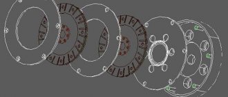
Fig.1. Driven (secondary) and drive (primary) shafts, engine starting mechanism: 1, 20 - ball bearings 304; 2 — washer; 3, 7, 9, 12, 16 — driven shaft gears; 4 - bushing; 5, 10 — gear clutches; 6, 11 — driven shaft couplings; 8 — bushings; 13 — bushing; 14 - driven shaft; 15 — keys; 17 — reverse idler gear; 18 — washer; 19 — gasket; 21 — bolt of the speedometer drive bushing; 22 — thrust bushing for speedometer drive; 23 — driven gear of the speedometer shaft; 24 — speedometer drive gear; 25 — disk of the elastic coupling of the cardan; 26 — washer; 27 — nut;; 28 — cotter pin; 29 — washer; 30 - coupling; 31 - gasket; 32 — ball bearing 205; 33 — gear wheel of the fourth gear of the drive shaft; 34 — gear of the third gear of the drive shaft; 35 - drive shaft; 36 - key; 37 — washers; 38, 39 — intermediate shaft gears; 40 - spring; 41 — bushing mounting screws; 42 — front bushing of the trigger shaft; 43 — rubber sealing ring; 44 - special washer for securing the end of the spring; 45 — gear sector return spring; 46 — gear sector; 47 — trigger shaft; 48 — wedge bolt nut; 49 — washer; 50 - wedge bolt; 51 — rear bushing of the trigger shaft; 52 — lever assembly.
The start pedal goes all the way down, but the crankshaft does not turn. To determine the cause, engage the gear and press the start pedal. If the motorcycle remains motionless, it means that the teeth of gears 38 and 39 (Fig. 1 - see below) of the ratchet mechanism or the starting gear sector 46 are broken and these parts need to be replaced. If the motorcycle moves slightly, the clutch is slipping and its drive needs to be adjusted.
To repair, the gearbox must be removed from the motorcycle and disassembled. These works are described in the instructions supplied with the machine by the factory, and usually do not cause any difficulties. Assembly is another matter. It is important here not only to install the parts in a certain order, but the main thing is to ensure the required nature of their connection. If, say, a gear must sit motionless on a shaft in order to rotate with it, then its hole in diameter must be smaller than the shaft. Conversely, a freely rotating gear must fit onto the shaft with a certain clearance. Deviations from these requirements, caused by wear of parts, disrupt the operation of the mechanism. Therefore, after disassembling and washing the parts, it is advisable to check their main dimensions, which must correspond to the values given in the table, otherwise, soon after replacing only the damaged part, the gearbox will have to be disassembled again to install a number of new ones. We recommend assembling the box in the following order, by unit:
Press into the cover 14 (Fig. 3) the ball bearing 17 of the drive shaft until it stops, the idler gear axis 15 is flush with the outer wall of the cover (tightness of at least 0.01 mm), alignment pins 16 and 19 (tension of at least 0.03 mm), rear bushing of the starting shaft (tension less than 0.025 mm) and oil seal 3. Install bracket 25, previously assembled with lever 24 and roller 22, and secure it with nut 5 with flat washer c. Install oil seal 1 into the hole for the driven shaft. Press key 36 into the drive shaft 35 (see Fig. 1) of the gearbox and then press gear 34 of the third gear onto it until it stops. The 0.05 feeler gauge should not pass between the end of the pressed gear without distortion and the shaft shoulder. Place gear 33 of the fourth gear on the shaft and bring its cams into full engagement with the cams of gear 34 of the third gear. Press ball bearing 32 onto the shaft until it touches the end of gear 33, put on gasket 31 and press coupling 30 onto the shaft so that it fits tightly onto the gasket. Place bushing 13 on the front end of the driven shaft 14 until it stops in the splines, onto it - gear 12. Press in two opposite keys 15, put coupling 11 on the shaft, and on it - coupling 10, bushings 8 and gears 9 and 7 on them. Press in the remaining two keys 15, put coupling 6 on the shaft, and on it - engagement coupling 5. Press sleeve 4 onto the shaft until it stops in coupling 6, put gear 3, washer 2 on the sleeve and press ball bearing 1 until it stops. gear 16, washer 18 and spacer 19. The entire set of parts assembled on the driven shaft will be secured when the ball bearing 20 is pressed onto its free end. All gears of the driven shaft should rotate easily on the shaft without jamming (radial clearance 0.02-0 ,1 mm), gear clutches - move freely along the splines of the driven shaft couplings. Once you are convinced of this, you can lightly lubricate all the rubbing pairs with oil, which will be used to fill the gearbox, in order to save the parts from dry friction in the first minutes of operation of the unit on the motorcycle.
Press gearshift disc axis 25 and lever lock axis 22 into crankcase 3 (Fig. 4). Screw the stop 20 of the cam-crank return spring to the crankcase with bolt 17. Screw the rubber buffer 28 of the gear sector of the trigger mechanism with lining 27 to the crankcase with two bolts 30 with washers 29 and nuts 26. The nuts must be secured with a cotter pin. Press in bushing 31 and oil seal 33 with spring 32. Press in intermediate shaft 13 with the short end. Place washer 37 on this shaft (see Fig. 1). gear 38 with the cams outward, then put the gear 39 with the cams on gear 38, the second washer 37 and spring 40.
Press axle 18 into the crankcase (see Fig. 2) and put pawl 19 on it. Install gear shift assembly with pedals into the pressed bushing 31 (see Fig. 4) and oil seal 33. Place the return spring 6 on the inside of the crankcase and place its end behind the protruding tendril of the stop 20 (see Fig. 4). Place cam-crank 7 on the splined section of the shaft (see Fig. 2), placing the second end of the spring behind the cam pin. Place spring 8 and ring 10 onto the second crank pin. Place the end of the crank pin into the shift pawl groove. Place washer 9 on the threaded end of the shift shaft and tighten it all with nut 12, which is secured with cotter pin 13. Install lever 23 (see Fig. 4) in the crankcase for engaging reverse gear. Install shift disk 11 on the axle (see Fig. 2) after first securing the gear shift disk retainer spring 17 to it. install lever lock 16 (see Fig. 2) on axle 22 (see Fig. 4), rest one end of spring 17 against the crankcase wall, and place the other end on the lock. Place washer 15 (see Fig. 2) on axle 22 (see Fig. 4), insert cotter pin 14 into the hole of the axle and separate its ends.
Now you can move on to the general assembly of the gearbox. Press the previously assembled drive and driven shafts into the crankcase. Insert gear shift forks 1 and 2 (see Fig. 2) into the grooves of the couplings switching the driven shaft and into the groove of gear 16 (see Fig. 1) reverse gear fork 3 (see Fig. 2). Insert roller 4 into the holes of the shift forks and install it in the corresponding hole in the crankcase. Insert the pins of gearshift forks 1 and 2 into the grooves of the shift disk, and insert the pin of the reverse gear lever into the groove of the fork 3. Screw the stop 14 (see Fig. 4) of the idler gear to the crankcase with screw 15. Screw in the sensor contact with plug 5. Install the assembled gearbox cover onto the shafts, having previously coated their planes and the gasket with some sealing compound. With light blows of a hammer (not steel), seat the cover until the planes touch and tighten the nine coupling bolts 7 crosswise (see Fig. 3) with washers 8 on them. In the assembled box, the shafts and gears should rotate easily by hand without jamming. Press drive gear 24 (see Fig. 1) of the speedometer drive onto the shank of disk 25 of the elastic coupling. Using light blows of a hammer, press the elastic coupling disk assembly onto the driven shaft so that the hole for the cotter pin is between the fingers of the disk. Place washer 26, tighten nut 27 as far as possible and secure it. Insert the driven gear 23 of the speedometer shaft into the hole in the crankcase, having previously lubricated its lower end with grease, insert the bushing 22 N through the recess on it and screw in bolt 21. To wind the return spring of the starting shaft sector, it is necessary to turn the front bushing 42 180° counterclockwise and secure it two screws. Install lever 52 on the protruding end of the trigger shaft and secure it with wedge bolt 50. Install the clutch release mechanism and screw in drain plug 9 (see Fig. 3) with washer 10 and breather 13 assembled with dipstick 12.
After installing the gearbox on your motorcycle, do not forget to fill it with oil.
That's the whole robot. If you understand it well, it’s not difficult at all - the main thing is to be careful!
Top 10 idiocy when assembling the Dnepropetrovsk transmission system
To follow up on the topic of “Why collective farmers don’t drive Urals.”
10. The top ten, of course, opens with the well-known broken ear of the lower right mount of the gearbox to the engine. KMZ (and possibly BMW) engineers played a great joke on motorcycle users by making three studs with nuts and one bolt, which can only be seen if you lie under the motorcycle. As a result, people often forget about the bolt and begin to remove the, for some reason, tightly seated gearbox from the engine with various tools, from a clock screwdriver to a crowbar. The result is that the ear remains on the gearbox, and the crankcase goes into non-ferrous metal. Although, I’ve seen them drive like that too.
9. Lubrication . There is an opinion among collective farmers that grease can lubricate gearbox and gearbox parts no worse than liquid lubricant. Like, “they even use grinders, and then there’s the speed!” And they push grease through the filler hole with a screwdriver. About half a kilo. “And there won’t be any leaks at all.” As a result, the lubricant is peacefully scattered by the gears along the walls of the gearbox, the gears rotate dry, the bearings, and even more so the bushings of the driven gears do not get anything. The result is hellishly devoured gear teeth (especially the fourth), tightly killed bushings, bearings... When disassembling such a box, half of the parts immediately go into a bag of ferrous metal. There are other extremes, in the form of strange liquids, such as drying oil... And sometimes with water (see photo).
8. Home-made parts . Tuning is, of course, good, but only with the right approach. What they don’t stick into the boxes... And the bushings of the driven gears are made of aluminum (bronze or metal-ceramic in their native), acceleration gears with a hardness of about forty, which wear out after a couple of hundred mileage, etc.
7. Washers. Adjusting . The collective farmer quietly hates them, I can feel it. There are 5 of them at the checkpoint. Two with a protrusion inside for the axis of the ratchet mechanism, one remote for the front bearing of the drive shaft, one hardened for the shaft under the front bearing of the drive shaft and an oil squeegee at the back of the driven one. No, they put them anywhere. In the blind, sometimes it seems. The result is, at a minimum, incorrect operation of the gearbox, possible knockout of gears, or even a jam.
6. Broken off clutch release lever ears on the crankcase cover. Yes, people often use a bolt and nut instead of the lost axis of the clutch release lever (which is under the cotter pin). Only few people realize that there is no way to tighten the nut there. Silumin is a fragile material. Doesn't spring. Tighten the nut a little, a “crunch” is heard - and the crankcase cover goes to at least welding, and at most to non-ferrous metal.
5. Customized mating planes . Sometimes you take it apart and there’s not enough evil. The previous owner dismantled the gearbox by driving a screwdriver (sometimes, judging by the damage, even a crowbar) between the crankcase and the cover. But there are three special protrusions on the cover, by tapping on which you can easily disassemble the gearbox through a wooden or aluminum spacer. And if the shafts are firmly seated in the bearings, then through a spacer on the bearings. And then they are surprised that the CP flows along the joint... And the same comrades rive the ball into the trash. Although if you put a piece of pipe on the vtorval and knock through it, then nothing bad will happen.
4. Broken crankcase covers during assembly . People, when putting the cover on the crankcase, sometimes hit all the protrusions with a hammer. Apparently without bothering to check whether the cover was warped, whether the axles of the forks and pawls, bearings, etc. were misplaced. The result is damaged landing seals and a non-marketable appearance.
3. The situation with the speedometer drive gear . People often forget that leaving the speedometer driven gear without a cable or plug is fraught with danger. When moving backwards (even half a meter), the gear is pushed out, it rests against the cable fixing bolt and... At a minimum, it bends the bolt so that it cannot be unscrewed, and at maximum, it breaks off a piece of the seat for the cable.
2. Sealant is evil! Or rather, he is evil - in the hands of an illiterate collective farmer (and he, a collective farmer, can be different). How does an illiterate collective farmer assemble a checkpoint? He generously spreads the sealant onto the mating surface of the gearbox housing, fits the cover, tapping it thoroughly with a hammer, and then attaches and tightens the bolts. Unaware that a considerable amount of sealant was squeezed into the threaded hole. As a result, the bolt presses the sealant down, compresses there, and the whole thing perfectly tears the crankcase under pressure. Many times I have seen crankcases with cracks near EVERY bolt. Rukalitso... It happens, however, that they do not use sealant, but gaskets (or even two) of enormous thickness. As a result, the driven shaft moves along the axis in the crankcase, which may well lead to a gearbox wedge...
1. The bearing was mixed up . When I took apart one of the boxes, I was quite surprised. Instead of the native 303 there was 204. What does this mean? A trifle... In total, the hole in the bearing is not 17 mm, but 20. As a result, the teeth of the 1st and 2nd gears are gnawed, the front bearing is killed to death. Well, yes, the bearing fit into the crankcase, the cover sat properly - that means everything is in order.
0. Well, the winner: 10 + 37 = 46 . Everyone knows that on the Dnieper gearbox there are ordinary first gears (10 teeth on the drive gear and 36 on the driven gear) and “lower gears” (9 on the drive gear and 37 on the driven gear). Once I opened the gearbox and was stunned: there is a shaft with a “regular” first one, and the driven one has a 37-tooth gear on it. It will not be possible to assemble a checkpoint with such a “set”. What did the collective farmers do? They took a grinder and made a “negative offset to the drive gear teeth.” Simply put, they were cut in height and shape so that the lid would fit. And it even drove, as can be seen from the presence of a contact patch...
These are the sad things.
Repairing the gearbox of a Dnepr motorcycle: One comment
Then, with light blows of a mallet on the fork disk and on the end of the input shaft 4, remove both shafts from the gearbox housing along with the gear shift forks. Press out all the removable gears from the shafts, and also remove all the keys and bushings. When pressing, use pullers or a press, such as the one in this article. And between the press and the gears when pressing out, use spacers made of brass or bronze. The details of the shafts are shown in detail in photographs 5, 6 and 7. Hello! Please tell me why 1st gear might fail and how to eliminate them? I will be very grateful for your answer
Source
How to remove a gearbox from a Dnepr motorcycle
REMOVAL AND INSTALLATION OF THE TRANSMISSION OF MOTORCYCLES “URAL”, “DNEPR”
To remove the gearbox from the motorcycle without removing the engine, you must:
— place the motorcycle on a stand;
— remove the rear wheel;
— Unscrew the nuts securing the main gear to the rear suspension arm;
— remove the main gear;
— remove the elastic coupling disc with the rubber coupling from the fingers of the gearbox disc;
— dismantle the suction pipes to the carburetors, the air filter and the battery;
— disconnect the flexible speedometer drive shaft by first unscrewing the nipple mounting bolt;
— Unscrew the clutch cable adjusting fitting from the upper head of the clutch release lever;
— unscrew the nuts of the box mounting studs and unscrew the box mounting bolt located at the bottom right;
— move the gearbox back and remove it from the frame to the front.
Install the gearbox on the engine in reverse order. Before installation, you need to check the alignment of the teeth of the hubs of the driven clutch discs and, if necessary, adjust them so that the teeth match. This can be conveniently done using a special mandrel or input shaft. The teeth at the end of the input shaft of the gearbox are adjusted (by turning the shaft) according to the position of the teeth of the hub of the driven clutch discs.
To put the gearbox in place, you need to push the clutch release rod forward, insert it into the square hole of the clutch pressure plate, then, moving the box forward, insert the input shaft into the splined holes in the hubs of the driven clutch discs.
CARE OF MOTORCYCLE GEARBOX “URAL”, “DNEPR”
Caring for the gearbox involves timely topping up and changing the oil. You need to use the recommended type of oil and change it after 4-5 thousand kilometers. The oil level should reach the lower threads of the oil filler hole.
During operation, there may be a need to adjust the gear shift mechanism. To ensure normal operation of the foot switch mechanism, the adjusting screws 10 (Fig. 4.9) must be installed so that at the extreme positions of the foot switch pedal, the locking holes of the 2nd and 3rd gears of the sector reach the lock ball.
The fixed position of the sector is felt when moving the manual shift lever 5. The need to adjust the switching mechanism appears when the sector locking holes do not reach or cross the lock ball.
Correct adjustment is checked using the manual shift lever. When switching with your foot from 2nd to 3rd gear (Fig. 4.28, b) (the rear arm of the shift pedal is lowered down all the way), if the locking hole of the 3rd gear of the sector does not reach the lock ball (Fig. 4.28, c) , the manual shift lever must be moved forward until the hole coincides with the ball. In this case, you need to unscrew the lower adjusting screw. If the locking hole passes beyond the locking ball (Fig. 4.28, d), the manual shift lever must be returned back until the hole coincides with the ball. In this case, you need to tighten the lower adjusting screw. The position of the engaged 3rd gear is shown in Fig. 4.28, d. When switching from 3rd to 2nd gear (the front arm of the shift pedal is lowered down all the way) (Fig. 4.28, g), if the locking hole of the 2nd gear of the sector does not reach the lock ball (Fig. 4.28, d), the manual switch lever can be turned back until the hole coincides with the ball. In this case, you need to unscrew the upper adjustment screw. If the locking hole passes behind the lock ball (Fig. 4.28, i), the manual shift lever can be turned forward until the hole coincides with the ball. In this case, you need to tighten the upper adjustment screw. The position of the engaged second gear is shown in Fig. 4.28, k.
The clutch release mechanism is adjusted when necessary. Using the adjusting screw (see Fig. 4.21), adjust the cable tension so that in the free state the clutch release lever (left lever on the steering wheel) has a free play of 5-8 mm.
Source