CLUTCH OF MOTORCYCLE “IZH”
If we consider the motorcycle transmission in order, then the first article should appear on the motor transmission - the first link of the transmission. But for various reasons we were forced to change our plan. And let's start this cycle with the second link - the clutch .
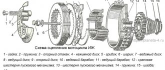
The clutch (Fig. 1) ensures the transmission of torque from the large gear of the motor transmission to the input shaft of the gearbox, short-term separation and smooth connection between them. IZh motorcycles use a friction multi-plate clutch operating in an oil bath. Let's consider the operation of the clutch using the example of the IZH Planet power unit.
The large driven gear of the motor transmission is made integral with the drive drum 8 of the clutch (Fig. 2). The driving plastic disks 6 fit with their protrusions into the grooves of the large drum 8. Between the driving disks, driven steel 5 are installed, which are connected in the same way to the small, driven clutch drum 7, mounted on the splines of the input shaft of the gearbox.
The package of disks in working condition is compressed by five cylindrical springs 2, which rest on cups 3, fixed in the outer pressure steel disk 4. The force of the springs can be changed using shaped nuts 1: during operation, this has to be done when replacing the package in order to move it evenly in the grooves drums The normal position of the clutch is constantly closed, the discs are pressed tightly and with great force against each other. To disengage the clutch, you need to separate the discs and move them away from each other.
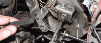
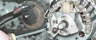
This is accomplished by a shutdown mechanism mounted on the right engine crankcase cover and a drive. The clutch release lever is located on the left side of the steering wheel. A cable 14 is fixed in it. When you press the lever, the force is transmitted through the cable to the worm 13; the latter turns, moves along the three-start thread and presses on the ball 11, the thrust rod 10 and the pusher 9 and moves the pressure disk 4, overcoming the force of the springs.
At the same time, the clutch discs are released from the force compressing them and are separated, the clutch is disengaged. As soon as you release the lever on the steering wheel, the release mechanism returns to its original position under the action of springs 2 and 12. Normal operation of the clutch mechanism is ensured only if there is sufficient clearance in the drive (free play on the release lever), and the springs are preloaded so that the disks move without distortion and over a sufficient distance.
Approximately, the spring force can be considered normal if the nuts protrude above the caps by approximately 4.5-5 mm. The clearance in the clutch release mechanism is, first of all, ensured by the adjusting screw 17. First, this screw must be screwed in until it reaches a noticeable stop (without, however, allowing the discs to move), and then loosened 1/2-3/4 of a turn and secured with a nut 16. Then use the adjusting screw on the steering wheel to set the free play of the clutch cable: it should be 5 mm at the end of the lever.
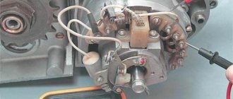
The clutch release mechanism of the IZH Jupiter engine (Fig. 3) differs significantly from that previously described in that it is interlocked with the gear shift mechanism. This allows you to disengage the clutch using both the lever on the steering wheel and the pedal, and gear shifting occurs more smoothly and quickly. The shutdown mechanism is also mounted on the right engine crankcase cover.
As in the previous case, it is connected to the lever on the steering wheel by a cable drive, the operation of which requires no explanation. As for semi-automatic clutch release, we need to talk about it in more detail. The gear shift pedal is mounted on the left end of the shift shaft; At the right end of this shaft 14 there is a cam 15 of the automatic clutch release.* The cam has a complex shape; in constant contact with its working surface there is a roller mounted on the end of a double-armed lever 19.
In the normal position of the shift lever, the roller is located in the cavity of the cam 15. When the lever moves down or up (this or that gear is engaged), the cam 15 with its protrusion runs onto the roller, through it presses on the shoulder of the lever 19; the second arm acts on the pusher 13, the ball 12 and the thrust rod 11 and moves the pressure plate 6. The springs 2 are compressed and release the disks, the clutch is disengaged. The working surface of the cam 15 is designed so that the clutch disengages earlier; what switches on this or that gear; It turns on only after the transmission is detected. You have to pay for convenience - in this case, with more complex adjustments.
If in the IZh Planeta clutch release mechanism it was necessary to adjust only the free play of the lever on the steering wheel, then on the Jupiter it is also necessary to adjust the free play of the shift pedal. Moreover, the sequence of adjustments is also important. Start, as in the first case, with the clutch springs. They should protrude above the cups by approximately 3.5-4 mm and ensure uniform, distortion-free movement of the discs when the clutch is disengaged. After this, screw 4 must be screwed into the pressure plate until it stops and unscrew it 1/4-1/2 turn. This may not work right away; for insurance purposes, it is better to perform this operation several times to be absolutely sure of the result. Then lock screw 4 with nut 5.
Clutch - disc replacement
Before replacing the clutch discs, motor chain or drive sprocket, it is necessary to remove the left muffler from the left driver's footrest (with a two-pipe exhaust system), drain the oil from the power unit crankcase, or (for repairs on the road) place the motorcycle on its right side.
If the fuel tank is full, the fuel must be drained or the tank removed. The work is shown on a removed power unit.
1. 12 mm
loosen the gear shift lever pinch bolt.
4. Remove the O-ring.
4. 14 mm
loosen the pinch bolt of the kick starter lever.
6. Using a slotted screwdriver, unscrew the eight screws securing the left crankcase cover. If necessary, you can use an impact screwdriver.
Please note that the screws vary in length and some have aluminum sealing washers underneath.
7. Remove the cover along with the paronite gasket. Be careful not to tear the gasket.
8. Using a large slotted screwdriver, unscrew the five nuts of the clutch pressure springs.
9. Remove the five springs along with the caps from the inner clutch drum.
11. We take out the driven and driving disks.
12. We lay out the disks in the order of removal, so that (in case of assembly without replacement) install them in their original places.
13. Inspect the clutch discs. The driven (steel) discs must not be deformed as a result of overheating, and the driving (plastic) discs must be free of cracks, burns and visible wear of the contact surfaces. The outer protrusions of the discs must not be damaged. If defective disks are found, we replace the entire set.
Installing clutch discs
We install the clutch discs in the reverse order.
Uniform compression of the springs is ensured by equal protrusion of the ends of the nuts above the ends of the studs. It should be equal to 4.0-4.5 mm (for new disks) and is measured with a caliper depth gauge.
The pressure plate should move without distortion or jamming. Otherwise, it is necessary to eliminate the distortions by additional adjustment with nuts.
Before installing the crankcase cover, it is recommended to degrease its seating surface and the crankcase seating surface, and apply a thin layer of sealant to them or to the oil-free gasket (on both sides).
The holes in the cover for the screws should also be degreased, and sealant should also be applied to the back of the screw heads.
After installing all the removed parts, you should adjust the clutch drive (see below), and, in addition, repeat this adjustment after several hundred kilometers of the motorcycle, when the clutch discs have become accustomed to each other.
Source
Setting up the Izh Planet 5 clutch
Motorcycles made at the Izhevsk Machine-Building Plant were considered one of the most reliable and comfortable. The motorcycles of the Izh-Planet and Izh-Jupiter series were especially different. A reliable and powerful engine, an improved gearbox and bearing lubrication, convenient clutch repair on Jupiter - all this made these motorcycles the best of their kind and few others at that time could compare with them.
But even such an ideal motorcycle as the Jupiter had one drawback, which was a poorly designed and ill-conceived starting mechanism. During startup, a so-called “reverse kickback” occurred, as a result of which both minor and fatal breakdowns could occur.
The main part of the repair of such a motorcycle is replacing the clutch on an Izh Jupiter.
How to change the clutch cable on Izh Planet 5?
That's right, you need to do 3 things: 1. Depress the clutch pedal 2. Shift to the desired gear 3. Release the clutch pedal
It's simple. I thought so too. But one fine day, while trying to complete step 1, I felt the cable make a “Pop!” and the clutch pedal sank to the floor. I've already experienced this somewhere...
What should you do in this situation? You need to instantly get your bearings and try to make the most of the current situation. well, kind of like Bruce Willis. “Damn, but I’m not Bruce Willis...” you say. Ha! So Bruce Willis doesn’t have this wonderful manual! Read on!
Pneumohydraulic trunk stops for VAZ 2115 in place of torsion bar
So, the situation is bad. We are in third gear and have no clutch. In addition, we are in the city and therefore it is impossible to get to our destination without changing gears (possible, of course, but very painful).
I immediately rejected option 2, since I did not have the skills to drive without a clutch and it was dangerous to continue driving.
how to FIX a clutch cable on a motorcycle QUICKLY and EASILY!?
Therefore, you need to look for the nearest parking place and drive there in gear. As a last resort, you can stand on the side of the road or take the right lane, but in this case our car can be towed by traffic cops.
Replacing the clutch cable and adjusting the clutch on Minsk cross
Unfortunately, I didn’t know a suitable parking place, and ahead was my favorite Bangalore roundabout, and I wasn’t going to drive through it without a clutch. Therefore, I put the gear in neutral (you don’t need a clutch for this) and temporarily stopped at the side of the road on Surganova Street opposite the Europe shopping center.
Profile pipes are common in industrial and private construction. They are used to construct outbuildings, garages, greenhouses, and gazebos. The designs can be either classically rectangular or ornate. Therefore, it is important to correctly calculate the pipe for bending. This will preserve the shape and ensure the structure’s strength and durability, on the website https://avtoindustriya.com/gruzovye-avtomobili/gruzovye-avtomobili-kitay/faw/.
Metal has its own point of resistance, both maximum and minimum.
Maximum load on the structure leads to deformations, unnecessary bends and even breaks. When making calculations, we pay attention to the type of pipe, cross-section, dimensions, density, and general characteristics. Thanks to this data, it is known how the material will behave under the influence of environmental factors.
We take into account that when pressure is applied to the transverse part of the pipe, stress arises even at points distant from the neutral axis. The zone of most shear stress will be the one located near the neutral axis.
During bending, the inner layers in the bent corners are compressed and reduced in size, and the outer layers are stretched and lengthened, but the middle layers retain their original dimensions after the end of the process.
The gun that fits you goes where you look. This way, when you bring the butt of a shotgun to your face, you can pull the trigger without hesitation, confident that whatever you are looking at will receive a load of pellets right in the center. In addition, the gun that suits you is easier to handle and much more enjoyable to shoot, visit https://avtoindustriya.com/gruzovye-avtomobili/gruzovye-avtomobili-kitay/faw/.
How do you know if your gun is right for you? Most people pick up a gun, shoulder it, and lean into the sights. If the aiming line matches the expected one: “It fits well.” The downside to fitting is using a test gun with a fully adjustable stock. You shoot at a steel plate or at skeet, and at this time the master adjusts the dimensions of the stock to suit you.
Although full adjustment is a very useful thing - you can adjust the gun to suit yourself. An increasing number of shotgun models—Browning, Benelli, and Beretta semi-automatics, as well as Mossberg pump-action shotguns and semi-automatics—are sold with shims and spacers that allow you to change the bevel, drop, and length of the stock. With other guns you'll have to improvise.
Gunsmiths use 91cm or 121cm square steel plates coated with paint or lubricant to show the shot grain when checking the fit of a gun. If you don't have a plate, you can use a sheet or plastic tablecloth. Hang it with a 5 cm reticle in the center. Use a choke with a strong constriction and stand at a distance of 14 meters. Use the gun unlocked first and gently lift it toward your cheek. Focus on the target and fire as soon as the gun touches your shoulder. Don't try to aim and don't look at the front sight. Repeat until a hole appears in the target. If the hole is located strictly above or below the mark, you need to change the bend (bend) of the butt. If it is strictly to the left or to the right, you need to change the tap. Each cm of displacement at a distance of 14 meters corresponds to 1.58 millimeters of change in the size of the butt.
Clutch drum Izh Jupiter
When repairing the clutch on Jupiter, keep in mind that the main element subject to heavy loads is the ratchet mechanism. This is what needs to be checked first. To do this, rotate the clutch basket so that you have access to the ratchet. Then remove the stop ring and disassemble the ratchet mechanism. Ratchet maintenance is carried out in several stages:
– The first thing you need to pay attention to is the teeth of the ratchet. They must be in good condition. Chips, bends or any other deformation are unacceptable. They also need to be sharp enough to have a good grip on the winding foot, otherwise the foot may slip. If the teeth are dull or deformed, the ratchet needs to be replaced. It is not necessary to buy a new one in the store; you can use a ratchet from another basket; problems with a “foreign” ratchet are usually not observed if it is in good condition.
– When replacing the clutch on an Izh Jupiter, another element that needs to be carefully inspected are the rivets on the ratchet. They wear out and no longer hold the ratchet securely. As a result, it may wobble. To check this, simply move the ratchet with your hand. If it is not securely fastened and there is movement, the rivets must be replaced.
– Next, you should check the condition of the teeth of the motor chain. It often happens that teeth become deformed over time. If this is not noticed in time, they will begin to turn in the opposite direction. If this does happen, the only way out is to completely replace the basket. It makes no sense to continue using it. An incomplete clutch repair on Jupiter will certainly lead to the fact that one day you will simply have to manually push the motorcycle.
– Sometimes it happens that the cast-iron body of the basket can crack. The only way to save such a basket is to weld the crack and then turn all the seams using a lathe. However, welding cast iron is a rather problematic task and not every welder will undertake it.
Clutch discs Izh Jupiter
If problems arise with the operation of the clutch, first of all it is worth carrying out a procedure such as checking the clutch discs on Jupiter, since it is due to wear of the discs that breakdowns most often occur. They may become deformed or burst. In this case, no matter how you adjust and repair other parts of the clutch on Jupiter, nothing will work or they will begin to function incorrectly.
You can find out their general condition by looking at the condition of plastic discs, since this is not so noticeable on metal ones. You need to look for cracks, concavities, chips. In order to determine the curvature of the disk, you can place it on a flat surface. If the disk sways from side to side, it is bent. If there is no obvious deformation, look at the protrusions of the work surface. Over time, they wear off and this can lead to negative consequences. If any signs of poor condition of the discs are found when checking the clutch on Jupiter, they should be replaced immediately.
Clutch adjustment Izh Jupiter
The next item included in the procedure for replacing the clutch on Jupiter is adjusting the alignment. In order to check the alignment of the teeth of the motor transmission, you must follow the following points:
– Place the adjustment washer and then the spacer onto the transmission input shaft.
– Take the spring washer and place it on the crankshaft journal.
– Install the outer drum and the main sprocket of the motor transmission. The sprocket must be firmly secured with a bolt.
– Using a ruler, check whether the teeth of the motor transmission are aligned.
Now you have two options: either the teeth are aligned and everything is fine, or they are not. If the teeth do not converge, their position should be aligned by adding or removing the required number of adjustment washers. Once you have adjusted the teeth, remove the drum and motor, but leave the adjustment washers and spacer. Then continue repairing the clutch on Jupiter according to the following algorithm:
– Mount the return spring main washer.
– Place the claw shaft onto the shaft intended for gear shifting and secure the return spring hook into the special connector.
Note. In order to avoid injury during the process of replacing the clutch on the Jupiter, the tension of the kickstarter spring should be done only by the cranking foot.
– Place the tab on the kickstarter shaft, secure it with the bolt and tighten the spring.
– Next comes the installation of a basket with a sprocket under the motor chain and the motor chain itself. To secure the sprocket as effectively as possible, place a small stick under the chain and then tighten the bolt as tightly as possible.
– Place a special control washer on the drum shaft, then screw on the nut and firmly fix the drum. It is important that the nut is tightened as tightly as possible.
– We continue replacing the clutch on Jupiter. From a selection of metal clutch discs, select the disc with the thickest thickness. It is persistent, the entire mechanism is based on it. If in doubt which disc is the thickest, look for one that has a small groove on the inside of the surface.
– Install the selected disc on the inner drum from the clutch basket with the inner side facing the engine. After this, place a plastic disk and then, installing the disks sequentially, form a basket. Keep in mind that before assembly, the clutch discs must be checked on Jupiter for possible deformation or defects.
– Place the clutch rod on the main shaft of the gearbox. Then put the pressure plate on the basket and insert the cups for the pressure springs into the special holes in the pressure plate.
– Insert the springs into the cups and secure them with nuts.
– After the clutch repair on Jupiter is completely completed, it is necessary to clearly adjust all the mechanisms.
Motorcycle IZH-Planet.
Operation, maintenance and repair. >> Front wheel, front brake. Front wheel hub - disassembly and assembly "World of Autobooks" LLC
Front wheel hub - disassembly and assembly
Disassembly
1. Remove the front wheel (see above) and place it with the brake cover facing up.
2. Remove the brake cover with pads.
3. Using a soft metal drift, carefully knock out the driven (worm) gear of the speedometer cable drive.
4. Using thin pliers, remove the drive gear along with its support sleeve.
5. Use a thin screwdriver to pry up the spring retaining ring of the right oil seal.
6. Remove the ring.
7. Remove the oil seal from the brake cover.
8. Using a special ring wrench or sliding pliers, unscrew the nut with the left oil seal. If the thread of the nut is “soured”, you can use a bit or chisel.
9. Remove the nut and oil seal bushing.
10. Remove the decorative cover.
11. Use a screwdriver to pry up the lip of the oil seal.
12. Remove the oil seal from the nut.
13. Remove the locking ring of the speedometer drive gear (screw).
14. Remove the speedometer drive gear.
15. Remove the oil seal bushing.
16. Place two wooden blocks under the wheel hub. Applying light blows through the bead on the end of the spacer sleeve (not on the ring of the right bearing!), we knock out the left bearing.
17. Remove the left bearing along with the spacer sleeve.
Attention!
The right bearing is secured in the steel hub bushing by two circlips.
18. Using special compression ring pliers or round nose pliers, remove the outer retaining ring of the right bearing.
19. On the left side of the wheel, applying light blows through the groove along the contour of the inner ring, knock out the right bearing.
20. Remove the bearing.
21. Use a screwdriver to press the brake pad away from the cam and throw the pad over the cam. We do the same with the other block.
22. Remove the pads.
23. Disconnect the tension springs from the pads.
24. Use a 10 mm wrench to loosen the tightening bolts of both brake levers.
25. To simplify subsequent assembly, use a marker to mark the shafts of the cams and levers.
26. Remove the levers from the cam rollers.
27. Uncheck the pad wear indicator, noting its position relative to the roller, unless we replace the pads.
28. Remove the cam rollers from the brake cover.
We wash the bearings, speedometer gears, cams and bushings in kerosene.
Cleaned bearings should rotate easily without noticeable play, clicks or jams. Oil seals should not be worn, cracked or hardened.
We check the condition of the teeth of the speedometer drive gears (they may be chipped), and the wear of the bushing.
Cracks are not allowed on the brake cover, and the wheel axle must be completely straight (checked with a metal ruler) and with undamaged threads.
We replace defective parts.
We replace brake pads with worn linings. If small scuffs or corrosion are noticeable on the working surface of the brake drum, remove them with emery cloth. In case of severe wear, cracks and deformations, we replace the hub (separately or as an assembly with spokes and rim).
We polish the working surfaces of the bushings along which the edges of the seals slide.
Assembly
Reassemble the front wheel in reverse order.
1. Fill the bearings with grease and press them with the open side into the bushing. When pressing, apply light blows to the outer rings of the bearings.
We coat the working edges of the oil seals and the helical gear with lubricant.
2. Having lubricated the surfaces of the cams and axles with grease, we install the parts in place, while orienting the pad bearings along the splines.
Attention!
Make sure that the lubricant does not get on the working surfaces of the pads and brake drum.
3. Install the pads with springs on the cams.
4. Set the wear indicator flag to mark 0.
5. Before installing the lower arm, uncotter the axle and disconnect the synchronizing rod from it.
6. Raise the lever half the length of the splined axis of the cam and use narrow pliers to insert the return spring behind the lever.
7. We push the lever along the splines until it stops and return the rod to its place.
Attention!
Before installing the synchronizing rod, especially if the pads have been replaced, it is advisable to check the simultaneous contact of the pads with the drum.
8. To achieve simultaneous contact between the shoes and the drum, without connecting the cable, simultaneously turn both levers until they stop (the upper one to the center of the wheel, and the lower one in the opposite direction). In this position, the hole in the synchronizing rod eye should coincide with the hole in the lower arm fork. If there is no coincidence, then, using an open-end wrench, unscrew the lock nut on the rod by 10 mm, and rotate the rod relative to its fork. This changes the length of the rod. Having achieved the coincidence of the holes, install the axle, pin it and tighten the nut.
9. Before installation, we also lubricate the driven gear of the speedometer cable drive and its bushing with grease. You can also pre-polish the pinion journals.
Contents :: Next >>