The gearbox of the Taiga st500d snowmobile includes a cover and a housing in which the shafts from the variator, rear-wheel drive, and brake devices are installed. Also built into the device are: 2 axles, track bushings, gears and other parts.
Gearbox device:
- Cam-type couplings are mounted on the shaft (VL) of the variator and reverse gear, which are needed to shift the gearbox and reverse gear.
- The overhead line and bushing are built into a box on bearings (ПШ), and the axles are bolted together. The splined end of the brake variator (CV) has a brake disc.
- The shaft, including the fork and the ball, which enters the axle groove during shifting, is the gear shifting mechanism. Structurally, the reverse start mechanism is similar to the design of the gearbox device, but 2 ditches are built into the overhead line.
- The upper half of the box body includes a mechanism containing levers with overhead lines and a cable with springs. Speeds, reverse and forward are switched by moving the lever. The second lever is located along with the hitch with the speed component, at the bottom - with the rear drive launch component.
To allow the box device to be filled with oil, its upper shell includes two holes: the first is covered with a plug, and the second is intended for draining liquid - it is closed. The level can be controlled with a dipstick.
Repair
To solve problems, take the measures prescribed in the instructions and follow the advice of specialists who encountered the same problem but successfully fixed it.
| Signs | Causes and method of solving the problem |
| Slow acceleration. The discrepancy with the technical parameters is very noticeable after a complete stop. | A) Look at the belt of the VR device. Often wear of this component is the cause of improper operation of the device. Replace the belt if the width is significantly less than the new product, i.e. by three millimeters. B) Check two geometric criteria: distance between pulleys and belt deflection angle. If there is a large bend, or the length between the pulleys is small, then contact the manufacturer (instructions). C) check the quality of the movable disk (MD) of the driven pulley. Replace the disk if it is broken. D) Check the spring tension. |
| It is not possible to accelerate under normal conditions to maximum speed at maximum speed | A) Look at the snowmobile under item one in the table. B) Inspect and adjust the minor pulley tension. |
| The variator greatly underestimates the gear | A) Adjust the spring tension adjustment of the non-main seam. If it is weak, then there is a high probability of a malfunction. B) Inspect the condition of the centrifugal regulator bushings. If there is contamination, then you need to clean the bushings. If broken, replace it. C) Check the backlash of the driven pulley disk, replace the disk elements if the backlash is not working correctly. |
Engine
Single carburetor engine (A)
Twin carburetor engine (B)
Engine technical data
| THE MODEL OF CAR | "TAIGA" ST-500D | |||||
| engine's type | RMZ-500 | |||||
| Number of cylinders | A | IN | ||||
| 2 | ||||||
| Cylinder diameter | mm | 72,0 | ||||
| Piston stroke | mm | 61,0 | ||||
| Cylinder volume | cm3 | 496,7 | ||||
| Compression ratio (geometric) | 10 | |||||
| Maximum engine speed (1) | ±100 min'1 | 6500 | 6800 | |||
| Gap at the junction of the piston rings | New | mm | 0,2 | |||
| Wear limit | mm | 1.0 | ||||
| Piston groove/ring clearance | New | mm | 0,03 | |||
| Wear limit | mm | 0,2 | ||||
| Clearance between piston and cylinder | New | mm | 0,08 | |||
| Wear limit | mm | 0,4 | ||||
| Connecting rod end clearance | New | mm | 0,2 | |||
| Wear limit | mm | 0,7 | ||||
| Crankshaft axial play (2) | mm | 0,3 | ||||
| Maximum runout of crankshaft journal journals | mm | 0,08 | ||||
| Ignition system RZP | ||||||
| Generator power | W | 135 | ||||
| Ignition | BSZ (thyristor) | |||||
| Spark plug | NGK BR9ES | |||||
| Spark plug gap | mm | 0,45 | ||||
| Ignition timing (3) | mm | 1,66 | ||||
| Sensor coil (4) | Ω | 3,5-4,5 | ||||
| Charging coil (4) | Ω | 550-600 | ||||
| Light coil (4) | Ω | 0,12-0,15 | ||||
| High voltage transformer (4) | Primary | Ω | 0,3-0,5 | |||
| Secondary | kΩ | 8-9 | ||||
| DUKATI ignition system | ||||||
| Generator power | W | 200 | ||||
| Ignition | BSZ (thyristor) | |||||
| Spark plug | NGK BR9ES | |||||
| Spark plug gap | mm | 0,45 | ||||
| Ignition timing (3) | mm | 1,66 | ||||
| Sensor coil (4) | Ω | 140-180 | ||||
| Charging coil (4) | Ω | 230-330 | ||||
| Light coil (4) | Ω | 0,05-0,6 | ||||
| High voltage transformer (4) | Secondary | KΩ | 5,1-6,3 | |||
| Carburetor | VM 32 | 2xVM34 | ||||
| GTZ | 250 | 210 | ||||
| Spray | 159 0-0 | |||||
| Idle jet | 25 | |||||
| Needle Identification - Clamp Position | 6DH8-4 | |||||
| Adjusting the float position | ±1 MM | 23,9 | ||||
| Mixture quality adjustment screw | ±1/16 rev. | 1,5 | ||||
| Idle speed | min'1 | 1600. | ..1750 | |||
| Gasoline type/octane number | AI-92 | |||||
| Engine lubrication - mixture of oil and fuel | 1:50 | |||||
| Oil injection system | E11 | |||||
| Adjusting the fan belt tension | Deflection (5) | mm | 8…9 | |||
| Force | kg | 5 | ||||
A – engine with one carburetor; B – engine with two carburetors
Engine speed at maximum power modes. The crankshaft axial play is not adjustable. At 6000 rpm (engine cold) with headlight on. All resistance measurements must be carried out with parts at room temperature (~ 20 ºC). Temperature significantly affects resistance measurements. The force applied midway between the pulleys to obtain a given deflection.
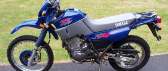
The snowmobile is equipped with a two-cylinder, two-stroke with loop crank-chamber purge, carburetor engine model RMZ-500, forced air cooling. Figure 13 corresponds to the basic engine configuration. At the consumer's request, the engine can be equipped with two carburetors, a separate lubrication system and an electric start system.
Crankshaft
The crankshaft consists of the left 4, right 30 and middle 31 axles and cheeks 32, interconnected by press fits. The crankshaft is supported by five bearings 2. The ends of the crankshaft emerging from the crank chambers of the crankcase are sealed with cuffs 3. A flywheel 29 (magdino rotor) is installed at the right end of the crankshaft, and a centrifugal variator regulator is installed at the left end.
Connecting rods
Connecting rods 33 provide articulated connection between the pistons and the rotating crankshaft. Needle bearings are installed in the holes of the upper and lower connecting rod heads. The radial clearance in the bearings is 0.012…0.024 mm. The specified clearances are ensured by sorting by diameter into size groups of bearing rollers, piston and crank pins and the corresponding holes of the connecting rods. The connecting rod hole group is marked on the rod near each head (numbers 1...6 for the upper head, numbers 1...7 for the lower head).
Pistons
Pistons 11 are cast from aluminum alloy. For piston rings, two annular grooves are machined on the side surface of the heads. Steel locking pins in the grooves secure the lock of each ring in a specific position, which protects the rings from breakage. In the middle part of the piston there are bosses with holes for installing the piston pin.
So that during thermal expansion the piston can move freely, it is installed in a cylinder with a gap. The gap between the piston skirt and the cylinder in a cold state is 0.08...0.10 mm.
To ensure selection of liners, pistons are produced in three size groups: M, S, B (small, medium, large). The designation of the size group is marked on the inner belt of the piston skirt. Based on the diameter of the hole for the piston pin, the pistons are sorted into two size groups: the group is marked with the letters B and C. When changing the piston, it is necessary to install a piston of the corresponding group.
Figure 13 – Engine – 1 – lower half of the crankcase; 2 – bearing; 3 – cuff; 4 – left axle; 5 – upper half of the crankcase; 6 – needle bearing; 7 – gasket; 8 – piston pin; 9 – lower piston ring; 10 – upper piston ring; 11– piston; 12 – cylinder; 13 – sealing ring; 14 – cylinder head; 15 – spark plug; 16 – spark plug tip; 17 – fan housing; 18 – bearing; 19 – driven pulley; 20 – fan belt; 21 – fan impeller; 22 – air intake; 23 – nut; 24 – roller; 25 – adjusting ring; 26 – manual starter; 27 – nut; 28 – drive pulley; 29 – flywheel; 30 – right axle; 31 – middle axle; 32 – cheek; 33 – connecting rod; 34 – hairpin
35 – exhaust manifold; 36 – intake manifold; 37 – intake manifold cover; 38 – clamp; 39 – intake manifold coupling; 40 – carburetor; 41 – recoil starter handle
The piston is installed in the cylinder in such a way that the arrow marked on the piston head is directed towards the outlet port of the cylinder.
Piston rings
Each piston is equipped with two piston rings 9 and 10, which provide the necessary seal between the piston and the cylinder and heat removal from the piston head to the cylinder walls. The ring lock has a thermal gap. When installing rings into the engine cylinder at a depth of 15...16 mm from the upper edge of the liner, the gap should be: at the top ring 0.20...0.45 mm, at the bottom - 0.20...0.35 mm. The gap between the ends of the ring and the groove when the ring is compressed to a diameter of 72 mm should be 0.03...0.07 mm at the lower ring and 0.035...0.08 mm at the upper ring.
Piston pins
Piston pins 8 are designed to articulate the piston with the connecting rod. Based on their outer diameter, piston pins are sorted into two size groups. The groups are marked with the letters B and C on the outer surface of the finger. When assembling, the pin and piston are selected from the same group.
Cylinders and cylinder heads
Cylinders 12 consist of an aluminum jacket and a liner pressed into it. To ensure selective assembly of the liner-piston interface, the cylinders are produced in three size groups. The size groups are designated by letters (M, C, B) and are marked with impact on the belt at the lower end of the cylinder. When changing a cylinder, it is necessary to install a cylinder of the corresponding group. The 14th cylinder head is installed on the upper end of the cylinder. To ensure the required degree of compression, the heads are produced in four size groups and are marked with numbers 1…4. A rubber sealing ring 13 is installed between the head and the cylinder, and a gasket 7 is installed between the lower end of the cylinder and the supporting plane of the crankcase. Each cylinder and head are secured to the crankcase using four studs. To avoid unacceptable deformation of the head and cylinder, during assembly the stud nuts are tightened crosswise in two steps: first preliminary, and then finally with a tightening torque of 2.2...2.4 kgf-m. The nuts should only be tightened when the engine is cold.
Carter
The crankcase consists of two halves 1 and 5. The crankcase halves are connected to each other with bolts and screws, tightened with a torque of 2.2...2.4 kgf-m. During assembly, the crankcase connector planes are lubricated with sealant. To ensure alignment of the crankshaft support bearing bores, both crankcase halves are machined together and are therefore not interchangeable. Four studs 34, screwed into the bosses of the lower half of the crankcase, serve to secure the engine to the sub-engine base. The magdino base and fan housing 17 are installed on the crankcase flange on the right side.
Engine cooling system
The air cooling system is designed to remove excess heat from the engine and includes a blower fan and air shrouds. The basis of the fan is the housing 17. In the housing, on two oil-filled bearings 18, a roller 24 is installed with a driven pulley 19, consisting of two half-pulleys, and an impeller 21. The impeller is driven by a V-belt 20 from the drive pulley 28, mounted on the flywheel 29 Magdino. Nut 23 securing the pulley is tightened with a torque of 4.5...5.0 kgf-m.
The belt is tensioned by moving the adjusting rings 25 located between the half-pulleys to the outside of the rear half-pulley. When operating the engine, it is necessary to periodically check the tension of the fan belt. Under a force of 5±0.5 kgf, the belt should bend by 8...9 mm. Weak tension causes the belt to slip at high engine speeds and be damaged by heat. Strong tension damages the bearings of the driven fan assembly.
Grease should not come into contact with the belt.
Recoil starter
The recoil starter 26 is located on the fan housing flange on the right side of the engine. In the starter housing, the parts are installed on the axle in the following order: a return coil spring, a cover, a pulley with a cam and a cord wound into the pulley groove, a carrier, a washer, a spring and a ring that secures the parts on the axle. The inner end of the spiral spring is engaged in the slot of the pulley, and the outer end is engaged in the slot in the spring housing. When viewed from the inside of the starter housing, the coil spring winding should be directed clockwise, and the cord winding should be counterclockwise. The end of the cord is brought out through the hole in the starter housing and secured in the starter handle.
Exhaust system
The exhaust system is designed to remove exhaust gases from the engine cylinders into the atmosphere and reduce exhaust noise.
On snowmobiles with a single-carburetor engine, the exhaust system includes a muffler and a connecting pipe through which the muffler is connected to the cylinder exhaust pipe. The muffler is attached to the snowmobile body and connecting pipe by springs. The connecting pipe is attached to the cylinder exhaust pipe also using springs.
On snowmobiles with a two-carburetor engine, the exhaust system includes a muffler, which is attached by springs directly to the exhaust pipe of the engine cylinders and to the body of the snowmobile.
Engine mount
The base with the engine is mounted on the snowmobile frame at four points on the shock absorbers. An adjustable stop bracket is attached to the left rear engine base mount.
The engine is attached to the base using studs screwed into the bosses of the lower half of the crankcase. A steel bushing is installed on each stud between the engine and the base. The tightening torque of the nuts securing the engine to the base is 2.7…3.0 kgf-m.
To adjust the distance between the variator pulleys and ensure parallelism of the pulley axes, which is achieved by moving the base with the engine, grooves are made in the base. Adjusting washers are installed between the front shock absorbers and the base, designed to eliminate misalignment of the axes of the variator pulleys. After adjustment, the base fastening nuts are tightened with a torque of 2.7...3.0 kgf-m. During operation, the tightness of the nuts must be checked periodically, since displacement of the base with the engine leads to rapid failure of the variator belt.
Tightening torques for engine threaded connections
| THE MODEL OF CAR | "TAIGA" ST-500D | |||||
| engine's type | RMZ-500 | |||||
| A | IN | |||||
| Nm (kg/cm) Cold engine | Magdino base mounting screw | M5 | 5 (0,5) | |||
| Exhaust manifold nuts or bolts | M8 | 22 (2,2) | ||||
| Magdino flywheel nut | M16 | 70(7) | ||||
| M22 | 105(10,5) | |||||
| Crankcase screws, fan pulley | M8 | 22 (2,2) | ||||
| Motor base nuts or screws | M10 | 39 (3,9) | ||||
| Cylinder head nuts | M8 | 22 (2,2) | ||||
| Cylinder nuts or screws | M8 | 22 (2,2) | ||||
| MB | 9…10 (0,9…1,0) | |||||
| Fan shaft nut | M16 | 45…50 (4,5…5,0) | ||||
A – engine with one carburetor; B – engine with two carburetors
Video
How to disassemble the gearbox
Before disassembling the device, select the plane of the gearbox from the driven pulley (VS) with the right side, and the plane of the brake disc with the left.
Step by step, follow these steps:
- Take out the dipstick. Remove cover 1 from the gearbox shell by unscrewing screws 16. After that, remove the upper part 13, cuff 12, unscrewing 4 screws (numbered 14).
- Remove the rubberized rings (RK) 11 sealing the axles of three elements: variator, brake and reverse.
- Pull out bar 47 by unscrewing nut 45. Unscrew bushing 53 and remove cable 44 with spring 52.
- Unscrew sleeve 48 with bolt 61.
- Pull out lever 51.
- Partially remove the two axles 60 and 63 and remove the forks 64, 56, having previously installed the ball 57 with the spring 58. Remove the overhead line 60, 63 completely.
- In plugs 40, hole 010 should be drilled completely and the plugs removed from the gearbox shell.
- Remove the cuff 22. Using an aluminum drift, remove the brake overhead line 39 from the gearbox shell with the assembly unit, which is part of the support supporting the brake overhead line 39, from the shell of the box with PSh 5. It is important that this element fits into the left half.
Gears 35, 36, 38, as well as bushing 37 must remain in the gearbox body. Remove PSh 5 from brake shaft 39 using a press.
Using an aluminum drift, remove reverse overhead line 43 until bearing 5 is released from the left side of the gearbox. It is important to understand that the teeth are connected by moving them in a different direction. Rotate the reverse axis (VR) so that tooth 42 MT does not touch the elements of gear block 8 of component 2 at VR. The reverse shaft must come out so that you can remove the left PS 5. Use a puller to get the left PS 5 VL reverse. To remove MT 42 from the reverse axis, you need to remove the ring with spring 41.
CITD and other options for cylinder temperature control
Active participant
I took two options, first I’ll put it under a candle, after the guarantee I’ll probably drill it, on the Thermiko website there are installation instructions and insertion points.
Installation of an engine temperature monitoring device on snowmobiles such as “Buran” and “Taiga”.
Fig.1 Fig. 2 Rice
3 Attention: The thickness of the cylinder heads is limited to 22-24mm. To avoid through-drilling of the cylinder heads, drilling must be done carefully. Installation of an engine temperature monitoring device TSITD 2-1 on a snowmobile
Installation of the TSITD 2-1 engine temperature monitoring device on a snowmobile.
To install a digital engine temperature indicator TSITD-2-1, it is necessary to prepare a cutout measuring 42.5x92mm in the dashboard or hood of the snowmobile Fig. 1Photo1. Install CITD 2-1 into the prepared hole, using the side holders to fix the device in the panel. Lay the measuring cable in the standard electrical wiring fasteners. Connect the connector of the measuring cable to TsITD-2-1. Connect the power output of the measuring cable to the on-board network of the snowmobile, for example: to the headlight size or to the wires on which 12V appears when the ignition is turned on. Note: The device can be powered from both alternating and direct voltage 12V. When connecting the device to a constant voltage (+), the red (-) black wire of the device. Installation of temperature sensors TPT3-6 for snowmobiles “Buran and Taiga”: Drill a hole (not through) 19 mm deep in the cylinder head. in any of the four head mounting stiffeners, at a distance of approximately 12mm. from the stud, so that the sensor is completely recessed in the body of the head, and the pressure washer of the stud does not touch the sensor cable photo2-3. For drilling, use a drill with a diameter of 3.2–3.3 mm. Next, fill the prepared hole with heat-conducting paste (KPT8) and install the sensor in the cylinder head. A core is used to fix the sensor. Photo3. Install the second sensor in the other cylinder head in the same way. Mount the third (air) sensor on the inside of the front bumper (photo 4). Install the cooling casing. Using connectors, connect the sensors to the measuring cable. TPT 3-6R For the Lynx snowmobile: When installing temperature sensors (we recommend), use standard holes in the cylinder heads with a depth of 20 mm. and M6 thread. These holes must be refinished by deepening the hole by 6mm using a drill with a diameter of 3.5mm. Fig.2 The right cylinder head (for older snowmobiles) must be modified so that the left head temperature sensor nut does not interfere with the installation of the right head. To do this, you need to select a vertical axial groove 5 mm deep in the head. and 15mm wide. (Fig. 3 - photo 6). Install the right cylinder head, fill the standard hole with heat-conducting paste (KPT-8) and install a temperature sensor into it. Install the left cylinder head in the same way with a pre-installed temperature sensor. Mount the third (air) sensor on the inside of the front bumper (photo 4). Route the lead of the temperature sensor of the right cylinder so that it goes into the technological hole of the cooling casing on the variator side (photo 7). Secure the air cooling casing. Using connectors, connect the temperature sensors to the measuring cable. Installation of temperature sensors TPT3-6U (under a spark plug): 1) To install temperature sensors, it is necessary to remove the standard sealing rings from the spark plugs. 2) Place the temperature sensors on the spark plugs so that the brown plane is at the bottom, install the spark plugs in the standard places of the heads. When tightening the spark plugs, do not allow the temperature sensor washer to rotate, since the cooling lamellas on some snowmobile models are located very close to the spark plug, and can lead to a break in the temperature sensor cable.
Operating order of the device. Start the snowmobile, the indicator will display the current engine temperature, the upper indicator R (right cylinder) - the lower indicator L (left cylinder). When you press the button, the upper indicator displays the ambient temperature.
*Critical engine temperature: If the instrument display begins to flicker while the snowmobile is moving, then the engine temperature has reached critical (195ºC - 200ºC). It is necessary to immediately stop driving and let the engine idle for about 3 minutes to prevent burnout or jamming of the piston.
Source
Disassembly and replacement of bearings
It is necessary to remove the gears 35, 38 and 36 together with the brake axis bushing 37 from the body part 10 of the gearbox, unscrew the bolt 3 of the overhead line 2 of the variator and remove the washer 4.
Continue disassembly:
- Remove the spring ring 65.
- Pull axle 2 BP from the gearbox housing to the right side until its left gear 8 touches the inner wall of the gearbox housing. Use a puller to remove ПШ 5 of the left BP axis support.
- Remove adjustment ring 6, gear 8. Now the variator overhead line can be pulled out of the gearbox housing.
- Unscrew bolts 3 from intermediate shafts 29 and remove washers 4. Using extended bolts M8x1.25, pull out axles 29 to the left, starting from the upper overhead line (using a technological stop).
- Remove the idler gears 30 from the gearbox housing. Do not further disassemble the idler gears.
- Remove cuff 22 from the gearbox body.
Remove cover 18 by unscrewing screws 16. Remove RK 19 of the lower shaft seal. Using a press, squeeze out the splined VL 23 on the right with the left PSh 24 and the spring ring 26. They should not contain rollers, balls, or broken clips. Check the quality of the gear teeth.
How to Measure Snowmobile Engine Temperature
It is necessary to monitor the operation of the engine. Need to:
- Listen to the engine running.
- Monitor his temperature.
In order for the mode to be maintained at the desired level, all snowmobiles have a cooling system. It is better to control it using a special temperature sensor.
This is especially important to do on two-stroke engines.
Not all snowmobiles have sensors installed from the factory; therefore, on many it is highly recommended to install them yourself or in a workshop.
So, when a digital display is displayed on the dashboard, you can control the fairly accurate temperature of each cylinder.
Assembly
In advance, insert the gear 25 shoulders to the left side into the housing 10 gearboxes. Install the splined axle 23 with the inner plane on the right half, and the splined one on the left. During the assembly process, connect the key connector in gear 25 together with the key located on VL 23. Fix the gear on the shaft with element 26. Install component 22, left bearing 24, RK 19 and upper shell 18.
There is no need to press on the inner half of the bearing. Remove gear 25 from the body of the box, use a puller to remove the right bearing 24 of the lower overhead line.
Availability of DIY snowmobile repairs "Taiga"
To snowmobiles "Taiga" Quite detailed repair instructions are included. Therefore, having basic knowledge of mechanized equipment (passenger cars or scooters), you will be able to figure it out. The main thing is your time and desire.
For repair of "Taiga ST 500-d" you will need a set of necessary tools. In addition to the standard set of keys, you will need special tools to repair the engine, transmission, suspension or replace track linings. Purchase of all keys, measuring instruments and lubricants? it's not a cheap thing. However, if you do not plan to constantly run to the repair shop for any reason, then you will have to purchase everything you need.
Bearing quality check
Check reliability. Install the PSh with its shoulders to the left side, then secure the inner rings of the PSh 31 on the axles with 29 bolts 3. Mount the right bearings 5 of the VL brake and reverse into the gearbox body. Place the gears (35, 36) on axle 39 in advance with the shoulders of element 36 facing recess 35.
Follow these steps:
- Place sleeve 37 on brake shaft 39, moving the gears with the sleeve until the end of the sleeve connects with the end of the brake overhead line.
- Mount the VL 39 brake in the housing half of the gearbox, having previously installed the gear 38 with its shoulders facing the right bearing 5. Do not insert the VL brake into the bearing 5 in a disassembled form. Insert the assembled shaft 43 into a suitable PS 5 on the right side.
- At the end, install the entire gear 38 on the brake VL 39 with its shoulders in the inner part of the 5 side ring PN and stop the process of installing the brake 39. Place element 2 BP with MT 9 in the body half of the gearbox. In this case, component 8 must be located in its position on the variator axis.
Check that the gears are installed in mesh with each other.
Install the following items:
- ring with spring 65, part 22;
- details 5;
- elements for adjustment 6;
- parts 3 and 4, which lock the variator overhead line;
- rings, rubberized 11;
- cover 13 with element 12.
Install the elements for switching the speed mode and starting reverse movement. The order should be the reverse of dismantling work.
All about snowmobile skis
Sooner or later, all happy owners of snowmobiles have to deal with adjusting and fastening skis, fortunately, this does not require special skills or expensive tools. Many regularly change the shoes of their cars so that they drive even better, even making homemade skis from plastic pipes for this purpose.
Installing the box and checking the oil
The installation process is carried out in the reverse order of disassembly, and the balance of the pulley should be checked. Check the oil level using the dipstick. Normally, the liquid should touch the mark on the dipstick itself. After filling, the fluid level in the gearbox will decrease because the voids will be filled with oil. Check the level of this fluid again and top it up to the mark. To do this, remove part 67 from cover 1 of the gearbox shell.
Before adding oil, you need to thoroughly tighten parts 21 with additional gaskets 20 of the gearbox shell holes.
Availability of spare parts for snowmobiles "Taiga"
Spare parts, new skis, linings for caterpillar propulsion, glass, skis, parts for engine repair, etc. for snowmobiles "Taiga" can be ordered online stores. It is usually not difficult to get Chinese spare parts, but finding high-quality original parts is more difficult.
As we have seen, to be able to repair the “Taiga” yourself, you only need a little ingenuity. Over time, you will learn how to adjust snowmobile skis, adjust tracks depending on the type of snow or ice cover, replace glass, and much more.
Features of repair of a new type gearbox bulkhead
Repairing the gearbox in the Taiga 500 snowmobile is easier with a new type of bulkhead. The manual says that to remove the gearbox you need to remove the rear suspension and move the drive shaft. But in reality everything is simpler:
- Loosen the Taiga st500d caterpillar.
- Disconnect the gear lever.
- Disconnect the wire to the reverse sensor (preferably with a sensor).
- Pull out the brake disc with the brake itself (it’s better to leave the mount).
- Remove the four nuts securing the shift box to the frame.
- Unscrew the channel of the speedometer device.
- Pull the box off the shaft. You don’t have to drain the oil at this stage, because it is inconvenient to reach the drain element.
- Remove the top shell, unscrew the nut from the switching device element. Pull out the gearbox rod.
- Unscrew the cover of the gear base, remove the rubberized rings and unscrew the bolt from the overhead line of the VR device.
- Unscrew and remove the variator itself. Pry up the oil seal located underneath it and remove the ring.
- Knock out the shaft in the direction BP. Be careful, there is a spring with 2 balls under the coupling - it is important not to lose it.
- Having removed the gear and MT from the overhead line of the variator, pull out the shaft.
- Hit the end of the plug with a screwdriver and remove the gear from the MT.
- Drive out the brake and transmission shafts (rear-wheel drive).
Thus, it is easier to repair the new type of transmission bulkhead.
Modifications
The Taiga Varyag 500 snowmobile is a modification of another machine produced by RM - the Varyag 550. While working on this model, engineers were looking for new ways to improve the basic version, which would reduce the cost of production without losing quality at the same time.
Main differences
The new all-terrain vehicle turned out to be 15 kilograms lighter than the prototype. As a result, engineers had to abandon the electric starter in favor of a manual one, and also lighten the design of the front bumper. At the same time, the car did not lose any strength. But the most important and successful decision was the replacement of the 553-ml engine with an analogue with a smaller volume - 407 cubic meters.
Another modification of the model is a change in the center of mass. The 500th model received a low center of gravity, which was now located next to the drive axle of the snowmobile. This made it possible to achieve good vehicle stability when moving along steep slopes.
Expert advice
Wear of transmission parts is associated with improper operation of the snowmobile or a long period of use without mandatory maintenance. Snowmobiles, like other vehicles, require service and careful handling. By timely replacing the belt and pulley, you can avoid expensive repairs of the entire vehicle.
If you experience symptoms of transmission problems, contact a diagnostic service center. The company supplies high-quality tools and equipment. Specialists look at and recognize breakdowns, informing clients in advance of the time frame and prices for repairing the gearbox of a snowmobile model Taiga 500d.
Before riding, you should inspect your snowmobile. Carry out maintenance at the designated intervals prescribed by the regulations. For snowmobile maintenance instructions, refer to the appropriate category in your owner's manual. For all problems with diagnostics and maintenance of your snowmobile, contact your dealer.
There are breakdowns that can only be eliminated with the help of an experienced specialist with special tools. His help will be needed in the following cases:
- the engine and gearbox are not functioning;
- the electronic equipment system, optical system does not work;
- the radiator is damaged (deformed);
- faulty suspension;
- the presence of shell defects (dents, cracks, peeling of the varnish layer, rust, etc.);
- The snowmobile needs major repairs after an accident occurs.
Reliable repair work involves the use of original spare parts, which have been tested many times by the development company and are distinguished by high precision in execution and quality. A snowmobile that has undergone similar service procedures should last for many years.
Owner reviews
The Taiga Varyag 500 snowmobile model has mixed reviews from owners regarding fuel consumption. Some say that the SUV consumes too much fuel, others note that a full tank lasts for a long time. Many praise the car for its affordable price, but note a lack of comfort.
Eugene
“I purchased this model in 2013. I've been riding it for over five years now and I love it. As for consumption, it takes me 19 liters for rolled snow, and about 25 liters for freshly fallen snow. Although all two-stroke engines are voracious"
Danil
“I bought this “miracle of technology” in 2015. I was simply shocked when I discovered that the car consumes 40 liters per hundred kilometers. I contacted the service center and it turned out that the corrector cable was faulty. After replacing the part, the snowmobile began to consume 24-26 liters. Still, it seems to me that this is too much, despite the fact that the manufacturer claims 22 liters.”
Sergey
Filippovo: “I took the Taiga 500 two years ago. During this time the car never broke down. Used strictly for economic purposes, for walking livestock on the farm. I had to change the spark plugs from time to time, because when driving at low speeds, carbon deposits appeared on them. My device consumed about 18-19 liters per 100 km.”
Specifications
Technical characteristics of the Taiga snowmobile and performance characteristics:
| Brake system control | Hydraulic |
| Launch | Electric starter |
| Brake mechanism | Mechanical, disk |
| Rear shock absorber view | Hydraulic, pneumatic, single pipe |
| Gearbox type | Two-stage |
| Transmission | Variable speed drive |
| Snowmobile engine model | RMZ-550 |
| Track Parameters | Width - 0.5 m Length - 3.93 m Height - 22 mm |
| Track width | 0.9 m |
| Fuel tank volume | 40 l |
| Number of speeds | 4 |
| Hanging mechanism type | Telescopic |
| Track dimensions | 0.5 m |
| Drive axle suspension travel | 10.5 cm |
| Rear suspension mechanism | Slimy |
| Rear cart suspension travel | 19 cm |
| Front headlight | Halogen |
| Heated steering wheel | Eat |
| Engine power | 50 l. With. |
| Ignition system | Ducati CDI |
| Equipment weight | 280 kg |
Snowmobile Taiga Varyag 550 technical characteristics (dimensions of the snowmobile) have the following:
- width - 1.05 m;
- height - 1.38 m;
- snowmobile length - 2.99 m.
What are they?
In the good old days, metal skis were churned out by the thousands and fitted to virtually every model, and on spring sleds the design of the skis was not particularly important. For many years now, manufacturers have partnered with various snowmobile parts suppliers, who are constantly developing new models of plastic skis with improved performance. The use of high-tech plastic options allows the skis to flex to stay on track.
Many Russian and foreign companies produce reinforced plastic skis for most modern snowmobiles.
Some are suitable only for one specific model with the corresponding marking, while others have a more universal device for wide use. Efficient winter driving depends on proper design and provides improved handling in all conditions.
The weight of each plastic ski is about 2 kg, width from 130 mm, length from 1 meter. At the same time, the supporting area is about 1 m2, which makes it possible to demonstrate surprisingly high cross-country ability in powder. The thermoplastic from which they are made has unique properties, great flexibility and the ability to take on most of the load upon impact.
Manufacturing
Not everyone is ready to spend money and maintain such a machine, so savvy craftsmen quickly figured out how to convert the dusty walk-behind tractor into a homemade snowmobile or, as it was called in the Soviet Union, a motor sleigh.
Skis are the simplest part that you can easily make with your own hands. Metal is rarely used for their manufacture due to their heavy weight, because the motor of a walk-behind tractor is not very efficient anyway (up to 15-20 km/h), and there is no point in making the structure additionally heavier.
The easiest way to make skis is either from factory plastic linings or from ordinary plastic pipes. To do this you will need:
After the pipe is cut lengthwise, it is heated until it begins to straighten, this takes on average up to half an hour.