Scooters are used by both fans of two-wheeled transport and those who save on fuel. The scooter still remains an indispensable assistant for both. But like any other vehicle, it also sometimes requires attention. For example, periodic tuning. Incorrectly adjusted valve clearances can cause a lot of trouble for the owner. Below we will look at valve clearances on a 4-stroke scooter, or rather their settings.
Although four-stroke scooters are reliable, they also require maintenance. If they do not receive service on time, then over time you can end up with serious sums of money. If you feel a hum or knock in the engine that was not there before and is not typical for standard engine operation, then something is wrong. It's probably time to start regulating. It’s a pity not everyone understands this, some just drive with it and then wonder why repairing such a small vehicle is so expensive.
It is recommended to check valve clearances on a scooter regularly (especially clearances on a Chinese scooter). After about 3-4 thousand kilometers. It happens that a scooter can travel 10,000 and not have any extraneous sounds, but it happens that after 1000 km it needs to be adjusted. Regulation is recommended even if there is no extraneous noise after a mileage of 4000 km.
Adjusting valve clearance on 4-stroke scooters
Is your engine knocking or is it just time to check the valves?
We read, ask questions. Adjusting the valve clearance Whether to adjust it yourself or in a workshop, everyone decides for themselves. I would like to note that adjusting the valve clearance is not such a difficult task; anyone who knows how to turn nuts can handle it. All you need is attention and accuracy. This article will help you. When it is necessary to make adjustments - After the first 500 km, then according to the table of prof. works; — The scooter does not start or starts with difficulty; - Has difficulty gaining momentum; — Constantly stalls; — The motor makes a ringing noise.
Attention, it is not only incorrect valve adjustment that can cause these problems. Descriptions of common problems, possible causes and solutions will be published on our website. Attention: - Adjust the gap only ON A COLD ENGINE! — Remove the seat carefully, the plastic is fragile, especially at low temperatures! — It is possible that after adjusting the gap, the carburetor will need to be adjusted (read on the website). — Before removing the cylinder head cover, it is advisable to wipe the engine. After removal, make sure that no foreign objects get into the engine. — The author of the article does not bear any responsibility for possible harm caused by improper adjustment.
— Pliers — Phillips screwdriver — 9 and 8 mm wrenches (heads) — Feeler gauge for setting the valve clearance (we need 0.05 and 0.1 mm).
Step 1. Preparatory work. Prepare 3-4 jars or other containers for screws, nuts and other small parts. This way we won’t lose anything during the work process.
Removing the seat. Here we will need a 10mm socket wrench and a screwdriver. There are 4 nuts in the luggage compartment that need to be unscrewed (two on the sides of the seat lock and two on the bottom). Under the rubber foot mat there are 2 screws, which we also unscrew (see photo).
Next, carefully remove the seat along with the helmet box (luggage compartment). Below it is the engine. Now the motor is free and nothing bothers us.
To adjust the valves, we must find the top dead center of the compression cycle . I draw attention to this because the engine is 4-stroke and the piston can be at TDC 2 times per working cycle. To do this, remove the plastic lining of the fan for the generator:
Unscrew 2 nuts (M8) and two screws and remove the lining:
Step 3: Cylinder head cover. Remove the cylinder head cover:
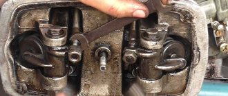
To do this, unscrew 4 M10 bolts and 2 nuts (the gasoline supply pipe is screwed on with nuts). Now we remove the cover and see the following picture:
To align the protrusion and the TDC mark, use a socket wrench and rotate the fan CLOCKWISE until TDC is reached. To find out that this is really TDC, lightly move the key, while the valve rocker arms should not move. If they move, then this is not TDC, turn the fan further, CLOCKWISE, until the mark and the protrusion align.
Well, we have found the top dead center, now we can start adjusting the valves.
Attention! If you are installing a new head, before adjusting, unscrew the valve adjustment screws as much as possible! Otherwise, due to carelessness, you can bend the valves.
Step 5: Adjust/Check Valve Clearance. To check the gap, take a 0.05 mm feeler gauge and try to insert it between the intake valve and the adjusting bolt.
If this fails (due to the absence or insignificant gap) or the gap is too large, then loosen the M9 lock nut and turn the adjustment bolt with pliers or a suitable wrench. Clockwise - the gap decreases, counterclockwise - increases. At the same time, hold the feeler gauge between the valve and the adjusting bolt.
The probe should fit tightly between them, so that the probe can be moved, but when moving, there should be no scratches on it. Tighten the locknut while holding the adjustment bolt with a wrench or pliers. After tightening, check the gap again.
So we adjusted the intake valve.
We do the same with the exhaust valve. Access to it with a probe is difficult, but possible. The gap here should be 0.1 mm.
The valve adjustment is now complete. We reassemble in reverse order, putting all the parts in place (head cover, fan cover, seat).
Let's see if we have forgotten anything. Tighten all screws, bolts and nuts accordingly. We work with plastic carefully! May break, especially at low temperatures.
When to adjust valves
Service work will also be required when troubleshooting engine problems, characteristic sounds, loss of power during acceleration, or when the bike stalls and it is impossible to start it.
To carry out repair work you will need a minimum set of keys and tools:
- Pliers;
- Crosshead screwdriver;
- A pair of horns for 8 and 9;
- Socket wrench 10;
- Probes 0.05 and 0.1 mm.
Adjustment of thermal clearances of valves of 4t engines
#1 Adjustment of thermal clearances of valves of 4t engines
Post by Kurgen » Aug 27, 2015, 00:11
The text is honestly taken from here. The most intelligent one, in my opinion. Added a little gag.
1. Valve clearances are adjusted on a cold engine (15-30°C). 2. Set the engine crankshaft to TDC on the compression stroke: • remove the plug from the inspection window in the engine cooling casing; • remove the valve cover. On some models this can be done directly on the scooter, in some you will have to disassemble half the plastic, and there are some that you will even have to remove the engine from the moped. We look at the situation ourselves. The direction of rotation of the motor is clockwise from the fan side. It is not allowed to rotate the crankshaft in a counterclockwise direction!
• by rotating the crankshaft, align the “T” mark (different manufacturers have different names) on the generator rotor with the protrusion on the crankcase.
for clarity, the plastic fan casing has been removed in the photo, but this is not necessary (remember the rubber plug for the inspection window, which we have already removed)
In this case, the camshaft must be in the position shown in the following photo
This is important: two small holes (sometimes also 2 notches) along the edge of the head, a large hole at the top. Only this way and no other way! 3. Using a feeler gauge, measure the gap between the pusher and the valve stem. For 150cc engines, valve clearances: intake 0.08mm, exhaust 0.1mm. We use these numbers only if there is no manual for the scooter. If you have a manual, check “our” gaps in it! (for reference, for “poltos” 0.03 and 0.07 mm)
The exhaust valve is almost always marked "EX" on the supports. (accordingly, the photo shows the inlet valve)
4. Loosen the locknut of the pusher adjusting screw using a 9mm wrench. The thread is right-handed.
5. Using pliers, rotate the adjusting screw while simultaneously monitoring the gap with a feeler gauge. The gap is set correctly if the feeler gauge moves in it with slight resistance, but not freely and does not wedge between the valve and the pusher. It is very important not to pinch the dipstick! It often happens that during tightening the feeler gauge is pressed and it changes its thickness. There is no way to check or correct this, so it is better to tinker with the tightening longer than to get a damaged dipstick.
139QMB 0.05 mm. — inlet, 0.1 mm. - high school graduation*
139FMB 0.05 mm. — inlet, 0.05 mm. - high school graduation*
157QMJ in 0.1mm standard. — inlet, 0.1mm. — exhaust* desired setting error (- 0.02) for the intake valve and (+ 0.02) for the exhaust valve total:
- at least 0.08 inlet and 0.1 outlet.
- maximum 0.1 intake and 0.12 exhaust.
- as an option 0.08 intake and 0.12 exhaust.
* - the setting is indicated at 20 degrees C. every 5 degrees C. from above reduce the gap by 0.01mm
6. Holding the adjusting bolt with pliers in the set position, tighten the locknut.
7. Once again we check that the gap is set correctly.
8. Adjust the gap at the second valve. Usually they start from the intake, but strictly speaking it makes no difference where to start. The main thing is to set the gap for the intake at the intake, and for the exhaust at the exhaust.
9. Install all removed parts in reverse order.
It is recommended to check the thermal clearances of the valves every 4 thousand km. If necessary, make adjustments.
Brumm Brumm 19000km I drove a car before it became mainstream
Source
Features of a gasoline engine on walk-behind tractors
The gasoline engine on agricultural machinery is often the most problematic part. It has many features that need to be taken into account during maintenance and setup. Peculiarities:
- There are two types of gasoline engines - two-stroke and four-stroke;
- the majority of the parts are universal, but a number of mechanisms will require spare parts from the manufacturer;
- a full installation is carried out with maintenance, which is performed at least once a year;
- most of the engines are of Asian origin, but are of sufficient quality and easy to maintain;
- For adjustments and other processes you will need to have the necessary tools.
Important! A video about adjusting the valves and the entire maintenance process can be found on the Internet, but only a person with experience and the necessary skills should carry out the procedure, since the mechanism is very sensitive to even small defects.
In this video you will learn how to adjust the valve in a walk-behind tractor:
Adjusting valves on a scooter
Many “happy” owners of Chinese scooters know firsthand how important timely adjustment of valve clearances is. I didn’t have time to adjust the valve clearances in time and that’s it—the valve burned out. It is especially important to check the valve clearances immediately after purchasing a new scooter, as sometimes the valves are “tight” from the factory. Which of course will lead to their burnout in the future, so beginners keep this point in mind.
Below are the basic recommendations when and in what cases valve clearances should be adjusted.
If you bought a new Chinese scooter, then do not even try to start it until you adjust the valve clearances. You also need to adjust the valve clearances immediately after break-in (1500 km) and then every 4000 km of the scooter. After removing the cylinder head (for example, you changed the piston group or replaced the camshaft, chain, gasket), it is necessary to adjust the valve clearances
About the design of walk-behind tractors and valves
Motoblocks Cayman, Patriot, Texas, Foreman, Crosser, Viking, Forza, Sadko, Don are a rather complex technical device , consisting of several main working units: engine, transmission, chassis and controls.
Understanding the design of a walk-behind tractor is very important, because the correctness of repair and adjustment work depends on it.
Let's look at each node in more detail:
- Engine . Depending on the configuration, 2-stroke and 4-stroke engines can be used. At the moment, 4-stroke engines are most widespread because they have higher performance indicators.
- In addition, engines are divided into diesel and gasoline. The former are most suitable for large-sized units, and the latter – for small and medium-sized walk-behind tractors.
For more information about the operation of the walk-behind tractor engine, see the video below:
- Transmission . The torque that is transmitted from the engine to the wheels is carried out through the transmission. It includes a gearbox, gearbox, clutch system and differential (for some models).
- Depending on the type of gearbox and clutch, not only the cost of the walk-behind tractor is determined, but also the operating principle of these components.
- Chassis. Most walk-behind tractors have a pair of wheels of various types - pneumatic or metal, equipped with lugs. In addition, the chassis includes the frame itself, on which all other elements of the walk-behind tractor are located - engine, gearbox, etc.
- Control system. All control of the walk-behind tractor is located at arm's length from the operator, i.e. on the handle and in its immediate vicinity. This includes the clutch lever, buttons for shifting speeds and changing movement, emergency engine stop, etc.
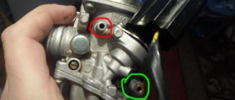
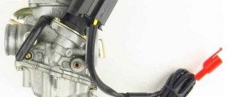
As for the carburetor, it is part of the engine power system. Acts as a kind of mixer that mixes liquid fuel with air to obtain a fuel mixture, which then enters the engine cylinders. Structurally, it looks like this:
- float chamber;
- diffuser;
- spray;
- throttle and air dampers;
- mixing chamber;
- jet, etc.
This is a description of a standard carburetor , but different models of walk-behind tractor, such as Huter, Profi, Plowman, Champion, Carver, Husqvarna, may use different carburetors, respectively, and the adjustment will be different.
Photo report: Adjusting valves on a Chinese scooter (139QMB, 157QMJ)
During operation of a four-stroke air-cooled engine (such engines are found on most Chinese scooters and motorcycles), the cylinder head (hereinafter referred to as the cylinder head) can heat up to 260 degrees. This is, of course, not the operating temperature, but this is often the peak temperature.
The valves that are located directly in the cylinder head itself heat up in the same way as the head, with the only difference that the intake valve heats up a little less since it is cooled by the working mixture, and it is ordinary atmospheric air saturated with gasoline vapors, and the exhaust valve heats up much more. Since a flow of exhaust gases passes through the exhaust valve, the temperature can reach 600 degrees.
The problem is that metal parts expand when heated. Valves are no exception: during operation, the valve heats up and becomes a little longer. And when the valve becomes longer, it simply rests against the gas distribution mechanism and opens a little, or rather does not close completely (squeezed), due to which gases under high pressure seeping through leaks melt the working edges of the valve and its seats.
The edges of burnt valves look something like this.
By the way, not only the valves burn out, but also the sockets in which they sit
And this is what the working edges of valves and seats look like after repair.
As you can see, there is little point in regulating something that has already gone bankrupt for a long time. A burnt-out valve will no longer hold compression. And if you find that one of the valves has been jammed, then feel free to remove the head and grind the valves, otherwise there will be no point.
Why valves require regular adjustment
Many happy owners of absolutely any equipment, be it a bicycle or a car, after making its purchase, completely ignore its needs and requirements, which is fraught with the rapid deterioration of most components, in particular the motor. The main function of the valves is to supply the air-fuel mixture into the combustion tank, as well as to ensure the removal of processed gases.
The valves operate under conditions of constant high temperatures, which leads to expansion of the metal parts of the assembly and their gradual deformation. Frequent expansion of metals during heating, combined with deviation from backlash, can lead to inadequate operation of the valves - the pusher may jam and the valves will stop closing, or significant backlash will arise at the junction of these elements.
When an unacceptable amount of play forms in the intake valve, this prevents the air-fuel mixture from filling the reservoir, since its area becomes much smaller, and then a pusher malfunction is inevitable. When play occurs between the exhaust valve and the pusher, the ventilation process of the cylinder is disrupted. In both situations, the driver will experience a significant reduction in engine power and a number of other characteristics.
If we are talking about a large backlash for this unit, then its main signs will be characteristic clicks, and the consumption will increase significantly. To summarize, we can highlight a list of various signs indicating the need to check valves and their further maintenance:
- The motorcycle or scooter has become harder to start;
- The bike stopped starting altogether;
- During the trip, cases of engine failure occur;
- The scooter stalls when trying to start;
- A drop in engine power, leading to a significant decrease in maximum speeds;
- Characteristic clicks or clattering sounds are heard from the gas distribution mechanism;
- The mileage after replacing the elements of the cylinder-piston group exceeded 500 kilometers.
Gaps
Here is the combustion chamber of an ordinary Chinese scooter engine.
During engine operation, the valves heat up to significant levels. And in order to compensate for the expansion coefficient of the valve and the entire timing belt as a whole, there is a small gap between the valve and its opening mechanism. Called thermal.
In our case, the gap that we will adjust is between the valve and the rocker arm adjusting bolt. By tightening the adjusting bolt within the required limits, we can adjust the thermal gap as much as we need.
But do not forget that the gap should not be very large - otherwise the mechanism will work with a shock load and quickly fail. And very small: the valve will heat up, hit the rocker arm and burn out.
Why adjust valves?
Many “riders”, when purchasing equipment, have little interest in its needs, which leads to rapid engine breakdown. The role of the valves is to supply the air-fuel mixture to the combustion chamber and remove exhaust gases. They operate under constant temperature conditions, and as you know, when heated, the metal begins to expand. Thermal expansion, together with gap deviation, leads to the fact that the valve may not close completely and the pusher is pinched, or vice versa, to too large a gap between the pusher and the valve.
If the intake valve has too large a gap between the pusher, then the combustion chamber is filled less with the mixture and the pusher breaks, and if the exhaust valve, the ventilation of the cylinder deteriorates. In both cases, this is felt as a loss of power and dynamic characteristics of the engine. When we talk about excessive clearance, then in this case the consumption may increase and a characteristic clattering sound can be heard.
That is, the engine requires adjustment of the gaps if:
- hard to start;
- does not start;
- stalls while driving;
- starts and stalls;
- consumption has increased;
- the maximum speed has decreased;
- a clattering sound is heard at the gas distribution mechanism;
- 500 km have passed since replacing the piston and cylinder group.
Tools
- Small pliers or special wrench
- Open-end wrench 9
- 14mm socket wrench or socket
- Socket wrench 8
- A set of measuring probes, preferably with a pitch of 0.02 mm
We free access to the cylinder head: depending on the scooter model, we remove the hood or seat tank. We find the valve cover there, unscrew the four 8mm bolts and remove it from the engine.
The valve cover looks like this. In my case, to get to it I had to remove the hood, saddle and seat tank.
There is a generator casing on the right side of the engine - remove it. If you are too lazy to remove it, just take out the plug. The plug is located in the upper part of the case and can be removed using a regular screwdriver. Through the plug we will control the position of the marks on the rotor.
We insert a 14 mm socket wrench into the center of the generator casing and turn the engine (clockwise) until the “T” mark (from the English “Top” means top, in our case the piston position is at TDC) on the generator rotor is exactly opposite the ledge.
After the mark on the generator coincides with the ledge on the engine crankcase, we check what position the camshaft is in. The camshaft should be in a position where both valves are closed. And it gets into this position every second revolution of the crankshaft since it rotates twice as slow.
The correct position of the camshaft is determined by its sprocket. The sprocket should become the large hole facing up, and the small holes and the marks that are knocked out near them should become parallel to the plane of the valve cover connector.
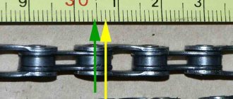
This is ideal, but in practice the asterisk rarely becomes the way we need it. And the chain is often to blame for this - it stretches and the camshaft begins to slightly not catch up with the crankshaft. If your sprocket has become a little crooked, then by and large it’s nonsense. But if you have it for some reason, then this problem needs to be solved very quickly - otherwise sooner or later the valve will bend.
Once again, check that the “T” mark on the generator rotor is opposite the protrusion, and that the camshaft sprocket is in the correct position. Unscrew the locknuts on the adjusting bolts.
We unscrew the adjusting bolts a little, insert a measuring probe between the valve and the adjusting bolt and, without removing it, tighten the adjusting bolt with our fingers, clamp the adjusting bolt with pliers and secure it with a lock nut.
After tightening the locknut, check how easily the dipstick moves. Ideally, the feeler gauge should move between the valve and the bolt with barely perceptible force.
- If the dipstick moves without effort, loosen the locknut and tighten the bolt a little.
- If the dipstick moves with difficulty or becomes jammed, loosen the bolt.
Step-by-step instructions for different models
Lifan 6.5
Adjusting the valves on the Lifan 6.5 walk-behind tractor consists of setting the correct gap under the valves. The sequence of actions will be as follows:
- Remove the casing to get to the flywheel.
- Remove the valve cover. Below it there are two valves - inlet and outlet.
- To check the intake valve clearance, you will need a 0.15 mm feeler gauge, and for the exhaust valve, a 0.2 mm feeler gauge. When adjusted correctly, the dipstick should pass under the valve quite freely.
- To adjust, loosen the fastening nuts using a wrench. We insert the dipstick between the valve and the piston so that it does not slip, but is held tightly enough in this position. We tighten the nut.
- Replace the valve cover and flywheel housing.
Valve of Lifan 6.5 walk-behind tractor
Adjustment of devices Neva mb 2, Zirka 105
The process of adjusting the valves on the Neva MB 2 walk-behind tractor and a similar Zirka 105 walk-behind tractor:
- Let the engine run and then cool a little.
- We remove the casing.
- We remove the valve cover and get to the flywheels that are under it.
- Unscrew the locknut.
- The blade that we insert into the gap should pass very freely between the piston and the valve .
- Screw the entire system back.
How to properly adjust the valve of a Zip walk-behind tractor
What is the procedure for adjusting the valves on the popular zip walk-behind tractor:
- Open the flywheel.
- Unscrew the valve cover clockwise.
- We check the gap with a feeler gauge exactly as described above.
- Use a wrench to turn the nuts and loosen them a little.
- We close the system and conduct testing.
How to set up on an Agro walk-behind tractor
The valves on the Agro walk-behind tractor are adjusted as follows:
- We warm up the engine , and then give it some time to cool down.
- Remove the oil bath of the air filter.
- Next, you need to unscrew the flywheel housing, which is secured with 6 bolts.
- The marks on the flywheel are 0 (top dead center), 5, 10 and 20 (fuel injection). We compare the dead center of the flywheel with a mark located on the cylinder so that they are opposite each other.
- Next, remove the valve cover.
- Below it are two valves. Loosen the locknut, then insert a razor blade under the valve. The blade must pass freely between the piston and the valve.
- Having achieved this, tighten the nut back . Then we return the valve cover and flywheel housing to their place.
It is worth noting that identical adjustment steps are carried out to adjust the valves on the Patriot walk-behind tractor. The Agros walk-behind tractor and its valve adjustment also correspond to the MB 1 walk-behind tractor.
So, if necessary, you can use an identical scheme.
Cascade
Adjusting valves on the Cascade walk-behind tractor:
- Remove the casing from the flywheel.
- Remove the valve cover.
- Turn the flywheel until the intake valve is pressed. Accordingly, the exhaust valve will be depressed.
- Next you need to achieve the correct clearance for each of the valves. According to the instructions, for the inlet this parameter is 0.15 mm, and for the exhaust - 0.20 mm.
- Using a feeler gauge, check the existing gap between the valve and the piston. If the dipstick slips a lot, or it does not pass between them at all, then we will need adjustment. If there is no probe, then you can use a razor blade, the thickness of which is 0.1 mm.
- To adjust, loosen the fastening nut, and then insert the feeler gauge into the space under the valve. Its optimal position would be a fairly tight movement between the piston and the valve, without slipping.
- If everything works out, tighten the nuts back , and then put the valve cover and casing back in place.
You should also approach valve adjustment on a Ural walk-behind tractor based on the instructions described above.
The operating scheme is arranged in an identical way, so you can use one algorithm of actions, exactly the same as for adjusting the valves on the popular Centaur walk-behind tractor.
Size of gaps
What I don't like about Chinese scooters is that they don't have any adjustment data. There is information about this on the Internet, but it is not always reliable.
It’s your right to believe me or not, but for my clients I adjust the gaps within the following limits:
- On engines of the 139QMB series (regular Chinese eighties), I set the gap to 0.05 mm - on both the intake and exhaust valves - the same.
- On engines of the 157 QMJ series (ordinary Chinese hundred and fifty) I set the intake to 0.05 mm and the exhaust to 0.07 mm