Nowadays it’s rare to find a “Planet” anywhere, especially in stock form. Grandfather's sheds where they once stood in abundance have long been cleaned out by the suffering, and the garbage dumps where they once lay are overgrown with grass...
The only place where you can still find something more or less decent is local newspaper advertisements. You can also search on Avito, but before you buy it there, see the product in person, otherwise they will send you a bag of bricks instead of an engine...
I was lucky: I found an advertisement in a local newspaper for the sale of an engine from a sidecar, went to the place, inspected it, made an agreement, bought it and brought it home. Don’t let the fact that the engine is from a motorized stroller scare you - the engine is completely identical to the original Planetovsky one.
In general, when I tossed the engine around, I was happy and immediately upset... I was happy because the engine was stock and had no signs of interference. There was also original oil and a USSR spark plug. I was upset because the piston and lower connecting rod bearing were killed.
I had a good factory cylinder in stock: bored to repair size + a factory piston, chrome rings and pin were purchased for it a long time ago.
I bought the connecting rod from an online store. We managed to find a factory one - not plasticine. I modified it a little: I made a small cut in the lower head to improve bearing lubrication, decompressed the crankshaft, threw out the old connecting rod, installed a new one and then centered the crankshaft using an indicator.
Tools
Tools you will need:
- Drill or screwdriver
- Metal drill 4 - 5 mm
- Flat file
- Technical hair dryer
- Mandrels. Plumbing fittings can be used as mandrels
- Powerful flat head screwdriver
- Open-end or socket wrench 14
- Clamp
- Hammer or mallet
- Oil can or syringe
- Sealant
Preparation
To perform a high-quality repair, the engine parts must be clean, the threads in the crankcase must be threaded, the seals and gaskets must be new.
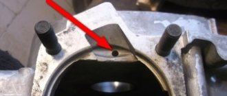
First, we clean the oil channels in the crank chambers. There are two channels in the Izh-Planet engine: one in the left half of the crankcase, the other in the right. We find the channels and if they are very clogged, we clean them with wire, rinse them with clean gasoline and blow them with compressed air.
Installation of bearings and seals
We install a retaining ring in the left half of the crankcase.
Depending on the model of the main oil seal, we install a spacer sleeve in the mounting hole of the main bearing, or, if the oil seal was initially wide (there are some), we heat the crankcase and, on the inside of the crankcase, place the oil seal until it stops against the retaining ring.
My engine had a regular narrow oil seal, so I put in a bushing.
Using a mandrel, install the main oil seal into the preheated crankcase.
Quickly, before the crankcase cools down, place the oil guide washer on the oil seal. The oil guide washer has a saucer-shaped profile. We place it on the oil seal so that the concave side faces us, and the curved side faces the clutch basket.
While the crankcase has not cooled down, we press the outer race of the main bearing into it using a mandrel.
If you are going to replace the main bearings with new ones, don’t be lazy: find a sheet of iron 7-8 mm thick, cut a wedge in it for the connecting rod, pass the sheet of iron between the cheeks of the crankshaft and use a mandrel to drive the main bearing onto the axle.
This way you will protect yourself from damage to the crankshaft. The main bearing has a very high interference and fits into the axle with a very large force. It is not uncommon for people to simply knock out the axle (the axle on the planetary crankshaft is pressed into the cheek) inside the crankshaft, but they were never able to put the bearing on.
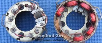
Native made in USSR 2505 KM
Replacing piston rings.
The approximate service life of piston rings in four-stroke engines corresponds to 10,000 - 15,000 km of motorcycle mileage. For two-stroke engines this period is much shorter (4000-8000 km). Lower numbers refer to engines having a smaller cylinder volume. By using high-quality oil and gasoline and installing a fine filter and an efficient air filter, the service life of the piston rings can be significantly increased. Compression piston rings are replaced if compression decreases, and oil rings are replaced when oil consumption increases, if it is determined that they are faulty.
Signs of wear on the piston ring, at which it needs to be replaced, are an increase in the gap in the lock (more than 3 mm), darkening of certain areas of the working surface and a significant decrease in its elasticity. Replacing rings when the gap increases within 1 mm is not practical. For oil scraper rings, an additional sign of the need to replace them is wear on the working edges.
To determine wear, the ring is inserted into the cylinder. The position of the ring is then adjusted by inserting the piston. The gap in the ring lock is measured with feeler gauge 3 (see Fig. 24)..
Before installing a new ring, you should check the gap in the lock, the correspondence of the height of the ring to the width of the groove and the thickness of the ring to the depth of the groove, as well as the fit of the ring to the cylinder mirror. Approximately, the gap in the lock should be 0.2-0.3 mm or approximately 0.1 mm for every 25 mm of cylinder diameter. The upper ring should have a slightly larger gap in the lock than the lower rings, since it heats up more when the engine is running. If the gap is small or absent, then the ends of the ring are cut off at the junction of the gap (Fig. 36, a). If the clearance is insufficient, the ring, which expands during engine operation, will cause the piston to jam in the cylinder. To work in a cylinder that has acceptable wear, the rings at the joint must be cut down so that the normal gap in the lock is in the middle of the cylinder and is smaller at the lower, less worn part of the mirror.
To check that the height of the ring matches the width of the groove, the ring is inserted with the outer side into the groove. The ring should, under the influence of its weight, fit tightly into the groove and roll freely in it. The gap between ring 2 and the side wall of the piston groove 1 when measured with feeler gauges (Fig. 36, 6) is approximately 0.02–0.06 mm for four-stroke engines and 0.05–0.1 mm for some two-stroke engines. If the fit is tight, the ring will not move enough, it will burn and get stuck in the groove. As the gap increases during engine operation, the ring will move between the side walls and oil loss will increase, and the side walls of the groove and the ends of the ring will quickly wear out; The ring may even break. Therefore, if the gap between the ring and the side wall of the groove is very large, then such a ring is not suitable for use.
The thickness of the ring can be reduced to the desired size by sanding its ends with fine sandpaper placed on a flat surface.
The compliance of the ring thickness with the groove depth is checked in the following way. Ring 2 with its outer side is inserted into the groove of piston 1 and a ruler 3 is applied with its edge to the piston, parallel to its longitudinal axis, as shown in Fig. 36, v. The ring should be recessed into the groove by 0.5-0.65 mm and move freely in the radial direction between the bottom of the groove and the ruler. If there is no movement of the ring, then when the piston expands and carbon deposits form under the ring, the outer surface of the ring will strongly press on the mirror, and the piston will jam in the cylinder. Therefore, it is necessary to select a ring with a smaller radial thickness or, in extreme cases, cut the ring from the inside.
To check the fit of the ring to the cylinder mirror, insert the ring into the cylinder and see if there is a gap between the ring and the mirror. If there are large gaps, the ring is rejected.
For two-stroke engines, before installing the rings, additionally check the mating of the recess in the ring lock with the stopper in the piston groove. In some cases it is necessary to install slightly larger rings. The ends of such rings should be cut off in the lock until the required gap is obtained. A ring with sawed off ends will work satisfactorily if its diameter before sawing off the ends in the lock exceeded the diameter of the cylinder by no more than 1-1.5 mm. If the initial discrepancy between the diameters is greater, the ring installed in the cylinder takes on an oval shape (Fig. 36, d) and will not fit tightly to the mirror. Filing the ends of the rings gives worse results when installing them in small diameter cylinders. It is better to install a run-in ring with an increased gap at the joint than a ring that does not fit well to the cylinder bore.
When installing a run-in ring with an increased gap at the joint, less gas passes into the combustion chamber through the gaps between the piston and cylinder. If a ring is installed that does not fit well to the cylinder bore, the piston temperature increases due to the small contact area of the ring with the cylinder bore.
Assembling the crankcase halves
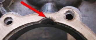
We degrease the connector of the halves, knock out the guide bushings a little so that they extend 5-6 mm above the plane. Depending on your desire, we assemble the checkpoint. Personally, I assemble the gearbox only after assembling the engine, it’s more convenient for me.
We apply any automotive sealant to the connector, install the second half of the crankcase, tap it with a mallet, install the gearbox cover and tighten the crankcase with bolts.
We do not pull the bolts anyhow, but strictly according to Feng Shui: we pull about a third of the force, first the middle crosswise, then the periphery, and gradually increasing the force over several circles, we tighten the bolts as much as is sufficient.
Replacing the piston.
The service life of a piston corresponds approximately to the time it takes for two sets of piston rings to wear on it. The piston's ring grooves, pin hole and skirt wear out. The limit of piston wear can be considered the formation between the lower part of the skirt and the cylinder mirror of a gap amounting to 0.005 of the cylinder diameter, which corresponds to 0.25 for cylinder diameters of 50, 60, 70 and 80 mm; 0.30; 0.35 and 0.4 mm. The clearance is measured at the lower edge of the front or rear side of the skirt with the piston located at the bottom of the cylinder.
In a four-stroke engine, the diameter of the new piston at the bottom of the skirt (along which the piston is selected to the cylinder), measured at a distance of 5-10 mm from its edge, is approximately 0.05-0.1 mm less than the diameter of the cylinder (see Fig. 24). Larger clearances apply to larger diameter cylinders. For motorcycle engines M-61 and K-750 and other engines with the same cylinder diameter, the gap is 0.08-0.1 mm. The diameter of the piston skirt of these engines is stamped on the piston crown.
For two-stroke engines, when selecting a piston, the clearance is measured either at the bottom of the skirt, or in the IV zone, under the lower piston ring. For example, in motorcycle engines M-104, K-58, Java and other engines with a small cylinder diameter, the piston is usually selected to the cylinder with a gap at the bottom of the skirt of at least 0.06-0.07 mm. The gap between the cylinder and the piston of the Kovrovets-175A motorcycle is measured at a distance of 20 mm from the lower edge of the piston. This gap is 0.06-0.08 mm for an aluminum cylinder with liners and 0.04-0.06 or - for a cast iron cylinder. When installing a piston from an aluminum cylinder into a cast iron one, the piston may jam. When using a piston from a cast iron cylinder in an aluminum one, the gap between the piston and the cylinder will be slightly increased, which will not significantly affect the operation of the engine. When measuring the gap between the piston and the cylinder under the lower ring, the gap should be in the range of 0.13-0.15 mm. The pistons of the Kovrovets-175A motorcycle are divided into size groups, indicated by the numbers 0; 1 and 2. The number 0 corresponds to the larger diameter, and the number 2 to the smaller.