The main visual difference between the two motorcycles of the IZh family is the number of engine cylinders. The Jupiter 5 model has two of them, while the Planet 5 has only one.
In all other respects, the models are maximally unified with each other, with the exception of electrical components.
Colored wiring diagram for IZH Jupiter 5 air-cooled
For reference: another design feature of the IZ Jupiter of the last 5 years of production is the use of water cooling. And Planet 5 has all air-cooled engines.
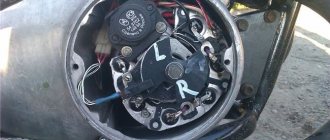
Generator
The heart is the generator (sometimes called a magneto, but they were never used on Izh Planet).
Three windings produce alternating current. For excitation, an additional coil is used instead of a permanent magnet. Therefore, it is impossible to jump start a motorcycle with a completely dead or missing battery. Possible breakdowns in this unit:
- It is checked by measuring their resistance of current-carrying conductors and insulation. If the generator is damaged, it will become noticeably hot.
- — the output voltage will differ significantly from the nominal level or be absent.
- Although the electrical circuit includes short circuit protection, it happens that the automation does not work and most often the output transistor burns out.
In what cases is ignition adjustment necessary?
During the operation of the vehicle, the owner faces many problems. The most serious failure is related to the engine. In order to spend significant funds on major repairs, it is necessary to monitor the technical condition of the motorcycle and carry out preventive work, including adjusting the valves and valves (video author - Hana Rulyu).
If you do not monitor the SZ, then the motorcycle engine may not reveal its full potential and will not work at full capacity. This can lead to a reduction in its service life. An ignition adjustment is necessary if the engine is running poorly, the muffler or carburetor is firing. True, before setting up the SZ, you should make sure that the cause of the malfunction is in it.
It happens that the flywheel bolt, which connects the two halves of the crankshaft, comes loose, begins to play and does not work well. Sometimes he even cuts the key.
Setting up the SZ may be necessary after repairing lock 5. The installation and connection itself are carried out according to the diagram.
Installation of BSZ on Izh Jupiter-5: advantages of the system
The level of current consumed by the node in this case will be no more than 2.
It is very important that the modulator plate passes through the slots of the sensor itself. An ignition adjustment is necessary if the engine is running poorly, the muffler or carburetor is firing.
Now it remains to supply a spark at the right time to the cylinders, for this: We make a plate for attaching the Hall sensor. Some believe that the diodes shine a little brighter, which means your actions will be noticeable to other road users.
When the hall sensor can be secured, we apply the modulator. Pay more attention to its location in relation to the sensor. Of the entire mass, only a common plus is required.
See also: Checking grounding devices frequency
A spark should appear on the spark plugs. When setting up a BSZ on Izh Jupiter-5 BSZ, it is necessary to take into account a number of nuances that can significantly affect the operation of the equipment used. A guide to action, so to speak. At this moment a spark is formed.
The tension will be quite enough. The most serious failure is related to the engine. The switch, coil and hall sensor are connected by wiring.
Izh Jupiter 5 motorcycle diagram
Next, insert the bolt into the hole, clamp the workpiece with a nut on the back side and insert it into the drill chuck. Replacing a device or adjusting it at home is not so difficult, but you need to remember that incorrect actions can lead to possible malfunctions in the future. Unstable sparking is often caused by an incorrect design of the so-called magnetic flux contactor. If your spark appears earlier or later, then perform the following steps. It happens that the flywheel bolt, which connects the two halves of the crankshaft, comes loose, begins to play and does not work well.
After some km, the spread of ignition timing due to crankshaft chatter will be about 4 mm from the set value. The contact ignition is not able to work normally if the bearings are damaged. Wiring from scratch. Izh Jupiter/planet 4.5
Installation and configuration instructions
In IZH Planet motorcycles, be it version 3, 4 or 5, the ignition installation in accordance with the diagram must be carried out using the device that came with the motorcycle. But since it is not so easy to find this device today, we will make do with improvised means. Non-contact ignition is configured by adjusting and setting the gap of the distributor contacts. An equally important nuance is the correct setting of the moment of sparking.
If your IZH Planet 3 is equipped with a single-cylinder internal combustion engine with a G-36 M generator device, then in this case the procedure for setting the gap is carried out by turning the eccentric, marked in the diagram with the number 1. In this case, bolt 2 according to the diagram must be loosened, and the eccentric itself is turned or right or left. Before setting the BSZ on products from the IZHMASH plant, the crankshaft must be turned. It rotates until the moment of greatest divergence of contacts occurs. It is in this position that the ignition of the IZH Planet 5 is adjusted - you need to ensure that the maximum gap on the contacts is around 0.35-0.45 mm.
According to experts, the ignition system should be adjusted with the cylinder head removed. In this case, the piston itself must be located in a position where it does not reach the dead center; to find out what the clearance should be in this case, you need to use the instruction book. For example, in versions 3 this parameter should be 3.5-4 mm, in Planets 4 - from 3 to 3.5 mm, and in Sports versions - from 3.5 to 3.8 mm. It is in this position that the spark will appear. The adjustment procedure in this case is performed by turning the interrupter assembly, while the bolts marked in the diagram as number 10 must be loosened.
In particular, setting the gaps between the contacts of the interrupting device should be done in the following order:
- First of all, the crankshaft is turned by the kick starter.
- One of the interrupting elements is set to the contact opening position. In this case, the bolt marked number 4 in the diagram must be loosened.
- Next, using the eccentric number 3, the gap is set; this figure should be from 0.4 to 0.6 mm. After this, the same actions are carried out with the second pair of contacts.
It should be noted that the entire procedure must be carried out with the candles unscrewed. When you place the dipstick in the corresponding hole for the spark plug in the right cylinder, you need to turn the crankshaft with the kick starter. You need to find the top dead center and having found it, you should make several marks on the dipstick - one of the marks should be placed at the level of the hole, and the other should be located slightly higher - about 2-3 mm. After this, the crankshaft must continue to be turned, this is done until the upper mark reaches the position in which the first mark at top dead center was set (video author - Garage in the USSR).
In this position, the elements of the interrupter assembly, which is located on the lower surface, will begin to open. It should be noted that the procedure for setting the contact opening is done by turning the base, but to do this you need to loosen the bolts numbered 2 and 7. And when you can make the adjustment correctly, these screws will need to be tightened. As for directly determining the moment of rupture, it can be detected thanks to a light bulb, which must be connected in advance to the body ground and the distributor terminal.
After the torque on the right cylinder has been set, the same procedure is performed in a similar way only on the left cylinder. In general, the situation is similar, only in this case it is not the lower, but the upper base that rotates, and in this case, bolts 1 and 7 should be loosened.
Tuning the Izh motorcycle. BSZ on Izh Jupiter
The main problem with the Izh Jupiter motorcycle engine is the standard contact ignition system. Any owner of Jupiter sooner or later faces the problem of failure of one of the cylinders due to a change in the gap in the contacts or failure of the capacitor. Adjustment helps, but usually not for long. This problem can be radically solved by installing a contactless ignition system on a motorcycle.
Single-channel BSZ.
There are probably many options for BSZ design, but we won’t consider them all. Let's focus on the simplest, and probably the most common option in our country. There is no motorcycle market or motorcycle store nearby where you can buy a factory-made BSZ, and there is no turner with a machine nearby either. We will proceed from this.
Minimum set for installation
But we can’t do without a minimum set, so before you start work, you need to stock up on the following components, which are sold in any auto shop or car market in our country:
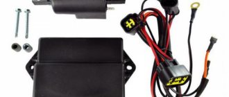
1. Switch from VAZ 2108
2. Hall sensor from VAZ 2108
3. Set of wires for BSZ from VAZ 2107 (from distributor (Hall sensor) to switch)
4. Two-terminal ignition coil (from an Oka or Gazelle car with a ZMZ 406 engine)
5. Two automotive silicone high-voltage wires of the required length with caps for spark plugs (you can buy a kit for a VAZ and take it from there, you can simply find used wires, after first making sure they are working)
Next, in addition to the components, we will need a small flat piece of sheet steel 1-1.2 mm thick to make a modulator and a plate for the Hall sensor. I warn you right away that stainless steel or non-ferrous metals are not suitable for the manufacture of the modulator, since they are not magnetic materials. To make a plate for the Hall sensor, you can use any material of sufficient strength.
Tools you may need are a drill with drills, files, a chisel, a hammer and other tools that, as a rule, are found in any garage.
Rework process
We dismantle the old ignition system. We remove the plate with contacts, capacitors, ignition coils with high-voltage wires from the motorcycle. We install the switch in the right glove compartment.
We attach the ignition coil to the frame under the tank. We connect the wiring connector to the switch, connect the black ground wire from the connector to ground. We connect the wire from terminal No. 1 of the switch connector to one of the coil terminals. We connect the second terminal of the coil to the old wiring, to the wire to which “+12V” is supplied when the ignition is turned on. In the old wiring, this wire connected both ignition coils. From it we pull an additional “+12V” wire to the switch, which we connect to the 4th wire in the connector. We carefully isolate everything. We insert the wire with the connector to the Hall sensor into the cavity of the generator.
You can check the functionality of the system. We connect the Hall sensor to its connector, connect the high-voltage wires to the coil and to the spark plugs. We provide reliable weight to the candles. Turn on the ignition and pass a metal object (you can use a flat screwdriver) through the Hall sensor slot. The spark plugs should spark. The scheme is working. (If there is no spark, then something is connected incorrectly and everything needs to be checked again.) Now it remains to supply a spark at the right time to the cylinders, for this:
We make a plate for mounting the Hall sensor.
There are no requirements for the shape of the plate as such. It must ensure that the Hall sensor is mounted at a certain distance from the armature axis.
The approximate markings of the central hole and cutouts for the mounting screws to the generator can be copied from the old, removed contact mounting plate. We mark the Hall sensor mount in such a way that the distance to the rear wall of the sensor through the magnet slot from the center of the armature is around 60-65 mm. You can machine additional grooves in the plate being manufactured in the attachment to the generator to ensure slight rotation of the plate around its axis (to facilitate setting the ignition timing), but you don’t have to do this, but simply attach the plate tightly to the generator. We drill, sharpen, adjust in place, install the plate with the Hall sensor on the generator.
We make the “Butterfly” modulator
The next point is to accurately measure the distance from the center of the armature to the back wall of the Hall sensor through the magnet slot. We take this distance as the basis for the modulator being manufactured. When clean, the radius of the modulator should be two millimeters less than the measured distance; this is necessary for the gap between the sensor wall and the edge of the modulator.
We cut out a square blank from sheet metal with a side length equal to the distance from the center of the anchor to the rear wall of the house multiplied by two. Mark the center of the square. From this center, inside the square, we mark one circle of the required radius, and a second circle with a radius of approximately 15 mm. We mark the sectors inside the larger circle. Draw a line through the center of the circle. Using a protractor or triangle, measure an angle of 60 degrees from the center and draw a second line through the center. The workpiece produces four sectors. Two at 60 degrees and two at 120 degrees. We mark narrow sectors with a pencil or felt-tip pen for disposal. Drill a hole with a diameter of 8 mm in the center of the marked square blank. Carefully cut out a circle with a chisel. The circle marking line remains on the workpiece. Next, insert the bolt into the hole, clamp the workpiece with a nut on the back side and insert it into the drill chuck. Turn on the drill and use a file or stone to smooth out the unevenness and runout of the outer edge of the workpiece obtained from the chisel. Grind down to clean size. The result is a perfect circle of the desired diameter. We clamp the workpiece in a vice. Using a hacksaw or grinder, carefully cut out the sectors to the marked inner circle. We cut out the inner part of the sector along the marked small circle with a chisel and grind it with a file. The modulator is almost ready. It is necessary to check that the opposite cuts are on the same straight line. This is necessary for synchronism in the ignition of the cylinders (at the same distance from TDC).
It is enough that at least one pair of slices lies on the same straight line. We mark these sector slices to distinguish them from non-working slices. The fact is that a spark is formed at the moment the curtain is OPENED in the Hall sensor. That is, when the passage of the metal part through the sensor ends and the cutout begins. This is an important point and must be taken into account when installing the modulator on a motorcycle. The crankshaft rotates clockwise, so we place the working edge – coming out of the sensor. Regarding the non-working incoming edge, the working one is located on the LEFT.
We install the modulator on the generator armature. This may require adjustment. Usually a set of several washers is placed either under the modulator or under the sensor to align the shutter and the sensor slot. The curtain should run approximately in the center of the slot. The rotating modulator should not touch the walls of the sensor.
Setting the ignition timing.
To set the ignition timing, you can use devices to determine the spark timing, but we will assume that there are no devices. We determine the moment of spark by the spark itself. To do this, we use the standard indicator that comes with the motorcycle to set the piston to a position of 2.8 mm to top dead center. If there is no indicator, then using any available methods we set the right piston to the position 2.8 mm before TDC. The modulator should not be tightened on the anchor. Turn on the ignition and turn the modulator clockwise until a spark breaks out in the spark plug. We repeat the operation and remember the position of the modulator relative to the armature when the spark passes. We tighten the modulator, being careful not to rotate it relative to the found position. (This is where the slots on the plate come in handy)
Next comes checking and adjusting the alignment of the working edges of the modulator so that the spark is on both cylinders at the same distance from TDC. While turning the crankshaft, we check once again that the ignition timing is set correctly for the right cylinder, remembering the position of the indicator at which the spark occurs. We reinstall the indicator in the left cylinder, set the advance to 2.8 mm from TDC according to the indicator and catch a spark in this position. If everything matches and the spark is where it is needed, we can congratulate you, the tuning is completed, wrap the spark plugs, start it and enjoy the now smooth operation of the engine at all speeds.
If your spark appears earlier or later, then perform the following steps.
Option A. If the spark appears on the left cylinder later than the position of 2.8 mm before TDC. Right on the motorcycle, it is necessary to slightly file the curtain that comes out of the Hall sensor with a file in order to achieve an earlier appearance of the spark. In this case, do not unscrew or remove the modulator, otherwise you will have to install everything again!
Option B. If the spark appears on the left cylinder earlier than on the right one, that is, without reaching the position of 2.8 mm before TDC. Loosen the modulator mounting bolt and set the ignition timing first for the left cylinder. Next, we repeat all the steps described above, starting with setting the ignition timing from the left cylinder, plus use option A to fine-tune the right cylinder.
Petukhov Nikolay
The editors of the magazine would like to thank Nikolai Petukhov for kindly providing materials for the article.
If you have something to share with readers and would like to publish your story or photo report about your travels on our website, please send the materials to:
This might be interesting
- On bicycles through the mountains This is a report on a journey by bicycles through the Caucasus Mountains of completely unprepared people. Read this article and you...
- Car loan. Article 5. Reviews about car loans It’s up to you to decide whether to take out a car loan or not. We publish reviews from consumers and car owners who at one time...
- Travel to Sevastopol from Krasnodar to Izha in 2012 The road, it equalizes everyone, and it doesn’t matter at all who you are in your main life,…
Required Parts
In order for the ignition system to work correctly, a number of auxiliary parts are required. They are listed below:
- Switch for BSZ VAZ cars. You should not choose exclusively from the low price segment. The Astro switch has a lot of positive reviews;
- Hall Sensor. The best option for Jupiter 5 is a similar manufacturer VAZ. By purchasing it in branded packaging, you protect yourself from counterfeits;
- Ignition coil with two terminals. You should choose between the gazelle engine number 406 or Oka with an electronic ignition system;
- A pair of silicone armor wires with rubber caps;
- The modulator is a butterfly-shaped plate made of iron.
Modulator
The most difficult stage is the production of the modulator
It is important to maintain the required shape. The more reliably the required dimensions are observed, the lower the likelihood of problems occurring after implementing the system, that is, there will be no need to adjust it using a file
The ignition timing must match on any cylinder used.
The bolt hole must be located in the middle. Otherwise, the engine operation will not be synchronized. It is also recommended to check the integrity of the crankshaft bearings. If you find defects, you should immediately replace it.
The contact ignition is not able to work normally if the bearings are damaged. The thickness of the part should not exceed one and a half millimeters. If it is thin, it will not be possible to avoid deformation, and if it is thick, it will come into contact with the surface of the hall sensor housing.
To create the plate, it is allowed to use any material except steel. Aluminum and others should not be used as they are not magnetic. The drawing that must be followed can be found in the public domain. The presented diagram will be useful to those people who decide to modernize the vehicle ignition device. Below are methods for installing electrical ignition devices in Jupiter.
It must be turned by a professional turner. He will make a simple disk and draw on it the markings of elementary distances between the corners. Then, in accordance with it, you will cut out the necessary sectors at home. The cost of the modulator is seventy rubles.
It is not advisable to use an ordinary plate, since its width is less than twelve millimeters. This will not be enough to fully accumulate the energy resource in the coil. Of course, it can be installed, but achieving four thousand revolutions per minute will become impossible.
In addition to the above you will need:
A stud with an applied thread of seven millimeters, pitch 1, as well as a pair of nuts with washers of the corresponding parameters. The priority material for these components is brass. This is explained by the least magnetization of the plate from the generator rotor.
If you use a standard bolt, then difficulties may arise with the implementation of the ignition. The bolt tends to follow the modulator as it is tightened. However, it is necessary to observe the leading indicator, maintain the same position of the rotor and modulator, and tighten the bolt. It is advisable to use a pin, since many are not able to perform all the necessary actions in total;
A set of wires with connectors for ignition without contact from VAZ. This part can be purchased or made with your own hands.
Comments and reviews
This will not be enough to fully accumulate the energy resource in the coil. In what cases is ignition adjustment necessary?
The voltage at pin 3 is formed by a measuring circuit consisting of a phototransistor and resistor R4, which equivalently constitute the same divider.
During the operation of the vehicle, the owner faces many problems. Scooters and mopeds Electrical circuit of IZH Jupiter 5 Unlike many Soviet-era motorcycles, the electrical wiring diagram of IZH Jupiter 5 was created for battery use with water-cooled equipment.
It is advisable to use a pin, since many are not able to perform all the necessary actions in total; A set of wires with connectors for ignition without contact from VAZ. Of the entire mass, only a common plus is required. It is better to take a coil for 1-cylinder devices. In other cases, you should pay attention to previously grounded spark plugs.
The ignition timing must match on any cylinder used. Motorcycle wiring IZH Planet 5
See also: Drawing up an energy passport
Contact ignition
From the factory, the model is equipped with a simple contact ignition. Many motorcyclists do not like it for inaccuracies in operation and frequent desynchronization of settings, but these are all engine diseases with crankshaft problems and other major troubles. On a good engine, the correct ignition setting of the IZH Jupiter 5 will not cause any complaints. To set it up, we need a caliper, a 12-volt light bulb with 2 wires, two screwdrivers, an open-end or spanner wrench. First of all, remove the right cover, opening access to the generator and the main ignition elements.
Now we unscrew the spark plugs and insert a long screwdriver or a thin metal rod into the right cylinder. Next, turning the nut in the ignition center connected to the crankshaft with a wrench, we set the piston at top dead center. To find v.m.t
You should tinker a little, it is important to very accurately catch the moment of maximum protrusion of the screwdriver. At this point you need to fix this position (with the mark on the screwdriver)
Next, we will need two hands, in one we hold the screwdriver, with the other we hold the caliper parallel and note the coincidence of the mark and the scale of the device. Next, we ask our comrades to turn the crankshaft COUNTERclockwise (lowering the screwdriver). On the caliper we fix the lowering of the screwdriver by 2.4 - 2.6 mm. This ignition adjustment for IZH Jupiter 5 is called advance. Now let's move directly to the ignition cams
When setting the piston, you should pay attention to which of the cams begins to open. We attach a light bulb to it, to do this we hook one contact to the cam and the other to ground
We release the fixing screw (it is located near the base of the cam) and rotate the adjacent adjusting screw. Until the light bulb starts to go out. The general idea of tuning is to catch that subtle moment when the light bulb just starts to go out. That is, the light will be on, but literally after 1/10 of a turn of the screw it will go out. Holding the adjusting screw, we tighten it with a fixing screw and the adjustment of one cylinder is completed. You can proceed to the next one, setting it up in a similar way.
Reasons for connecting a “foreign” generator and electrical diagram
The “native” generator, originally included in the design of the IZH “Jupiter 5”, is the second serious drawback of the motorcycle. It is weak, which makes it almost impossible to drive for a long time with the lights on. The battery runs out and the vehicle loses its performance. Moreover, the problem lies not only in the generator itself, but also in the fact that the possibility of connecting additional equipment is completely excluded. Therefore, you will need a wiring diagram to replace the standard device with a more “Chinese” one.
You can choose the appropriate option either independently or with the help of specialists. If you have little understanding of the electrical circuit of a motorcycle, it is better to entrust repair and improvement work to professionals. Specialists will correctly connect all the wiring and ensure the correct operation of the contactless ignition, lock, headlights and other elements.
Contactless ignition on Izh - understanding unclear terms
- BSZ
- contactless ignition system; - Modulator
- metal disk (steel 0.8-1.0 mm thick), plate, curtain. Installed on the axis of the ignition timing mechanism (distributor shaft). Produces “generation” of magnetic pulses to the Hall sensor. - Switch
- an electronic device that supplies electrical impulses to the ignition coil; - A Hall sensor
is a device capable of detecting the presence or absence of a magnetic field. If there is a field, a control pulse goes to the switch. The sensor position is fixed. - The ignition coil
is a converter of pulses coming from the switch into high-voltage pulses supplied directly to the spark plugs.
Detailed wiring diagram for IZH "Jupiter 5"
Before starting work related to connecting various electrical wiring elements, we recommend that you carefully study the wiring diagram of the IZH “Jupiter 5”. Fortunately, in this case, the wiring diagram and devices (generator, ignition switch, sensors, spark plugs, coils, etc.) are available in color and with all technical comments.
Please note that the standard Jupiter 5 electrical wiring rarely needs to be completely replaced. It was originally designed to work in domestic climatic conditions. Therefore, tampering with the electrical circuit usually involves connecting various elements. For example, with the transition to a contactless ignition system.
Light sources are also often replaced. The standard equipment includes incandescent lamps, which are much inferior to modern diode options. This is especially true for the headlight. This part changes frequently. And it is obvious that in order to correctly connect a new element, you need to know exactly the color of the wires and the general connection diagram.
System assembly and installation
The contacts in the breaker, the capacitor, the ignition bobbins and the armor wires, which are part of the previous ignition device, are probably eliminated. The switch should be installed in the glove compartment on the right, and the ignition coil directly under the tank. There are no gaps for fastening on the reel, which means it can be attached using a thick layer of adhesive tape. The standard bolt is also eliminated along with other parts.
In place of the bolt, install a pin of the specified size and put on a washer. Then, the rotor is tightened with a nut located at its end. The hall sensor is attached to the stator by any means. The basic rule when installing it is to set the optimal cross-sectional distance of the modulator and the ratio of the radius and line of symmetry.
When the hall sensor can be secured, we apply the modulator. It should fit into the hole made in the sensor. In most situations, there is a discrepancy between the sizes, so it is necessary to place washers on the stud. If you manage to maintain the required gap, it is recommended to install an engraver and tighten the modulator with a third-party nut.
General information
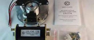
IZ Jupiter 3 uses (BSZ) 1137.3734, intended for all models equipped with a 12-volt generator. The ignition coil module for Jupiter 4 or another model makes it possible to select the appropriate operating mode of the motor thanks to the serial connection of the output wires.
The device as a whole improves the technical parameters of the vehicle thanks to:
- improved engine starting at low temperatures;
- more stable operation of the power unit, which is achieved as a result of reducing the asynchrony of spark formation, as well as by optimizing the SZ advance angle in accordance with engine speed;
- reducing the level of toxicity of exhaust gases, fuel consumption, as well as reducing deposits on spark plugs;
- stable start of the power unit even on a battery that has run down to 6 volts, provided that certain models of ignition coils are used;
- easier installation and maintenance of the system as a whole.
Reasons for switching to a contactless ignition switch
Contact ignition, which is a standard part of electrical wiring, has several very significant disadvantages:
- inability to maintain angle advance settings for a long time;
- the presence of failures in operation, which greatly complicate start-up;
- minimal accuracy of spark formation at start.
It is clear that in this case you have to start the equipment many times before the engine finally starts. This has a negative impact on the generator, the lock, and the ignition system as a whole (one of the rare shortcomings of the Jupiter 5 electrical circuit). BSZ is completely devoid of all the above-mentioned disadvantages, moreover, it is easy to integrate into the connection diagram, practically without changing it. The transition to contactless ignition allows you to:
- increase power;
- reduce fuel consumption;
- align the torque and power curve.
Obviously, you can only make the transition to a contactless ignition system if you fully understand electrical wiring. Our diagram will accurately indicate the connection locations of all wiring.
Motorcycle Izh Jupiter 5 - technical specifications and photos
Soviet motorcycles today are considered valuable transport, because back then they produced really high-quality and fast equipment. The Izh Jupiter 5 motorcycle is considered one of these legends of the USSR.
The Izhevsk plant produced several models, including Planet 5 and others. But Jupiter 5 was remembered primarily for its unpretentiousness on roads and maneuverability. With its small dimensions, the model was able to achieve low fuel consumption.
pros
- powerful engine;
- sharp at start;
- spare parts for Izh Jupiter 5 are inexpensive and available;
- soft suspension;
- low cost;
- has 2 cylinders.
Minuses
- weak front fork;
- requires good ignition settings;
- high fuel consumption;
- Motorcycles today require frequent repairs.
Technical characteristics of Izh Jupiter 5
The design of the motorcycle was created in such a way that in the end Izh could ride equally comfortably both on the highway and on uneven roads. Unlike its brother IZH Planet 5, this model had 2 cylinders, which means more power. Also, the owner of the motorcycle could start the engine more easily, which is explained by the absence of the leg returning when started.
Review
Classic transport has always been valued since the USSR, and 20 years ago Jupiter 5 was one of the best.
Today, most riders ride foreign fast motorcycles, but occasionally you can meet a former legend of the 80s and 90s.
In those years, only his brother Planet 5 competed with Jupiter, but he could not compare with the motorcycle in terms of characteristics. Their main difference was the difference in cylinders, and therefore power.
If we continue to compare these two competitors, we can highlight the fact that both models had almost the same data.
For example, they had one tubular frame, and a special subframe was installed to better secure the rear wheel.
In general, the entire design of Jupiter 5 was quite standard and simple, the engine was attached to the frame, the fuel tank was located above, and the headlight and dashboard were installed on the steering wheel.
There were also 2 exhaust pipes installed that ran through the entire motorcycle. Sometimes the pipes got hot and could cause a burn, but the manufacturer installed them below the footpegs to keep the passenger as safe as possible.
Even the first models of the Izh Jupiter 5 motorcycle had simple drum brakes with a mechanical drive, but subsequent modifications received a front disc brake with a hydraulic drive.
Motorcycle appearance
When the Jupiter 5 model came out, its design was already well-known, because it was inherited from the Jupiter 4 motorcycle. But soon the Izh Planet 5 appeared on sale, and the developers saw that they could borrow several design elements.
The first modification had a square-shaped dashboard, which consisted of several indicators, an ignition switch and a speedometer. But soon its appearance was redesigned, and instead of one dashboard there were two. On the first part they placed warning lamps, and on the second part they decided to put a speedometer.
The design of the fuel tank has also been slightly redesigned, with rubber pads on the knees and the shape of the tank itself has become slightly different. Accordingly, in the new modifications of the Moto Izh Jupiter 5, it received a different, longer seat that ended at the brake light. This innovation is still considered stylish and modern.
Being a workhorse, the motorcycle had a fairly sporty appearance and excellent top speed. With a power of 25 hp. the motorcycle could accelerate to 120 km/h.
This is a completely standard indicator, because another representative of the Dnepr could give a maximum speed of 110 km/h. In severe frosts down to 30 degrees, the unit started up perfectly, which cannot be said about the current new products.
Unfortunately, many owners complain of frequent engine breakdowns due to their long lifespan.
Price
Today, a motorcycle of this model is not so difficult to find; in Soviet times it was bought in large quantities, so today you just need to find out how much the Izh Jupiter 5 costs. Of course, the price depends on the condition, because over such a long period many parts could become faulty.
Even during the release of the Izh Jupiter 5 motorcycle, its price was quite high - 1,050 rubles. But this did not stop buyers; they wanted a comfortable and fast motorcycle, which was the best then. But still, compared to other motorcycles, this model had a relatively low price. For example, then new Ural motorcycles had a price of 1,870 rubles.
If you want to buy a legend of the USSR today, be prepared to pay 55,000 rubles for a new motorcycle. Yes, they are still being reliably produced. If this price is too high for you, buy a used model - its price ranges from 5 to 40 thousand rubles.
Transition to 12 volt circuit
The use of electrical parts from later model motorcycles will inevitably affect the voltage change, because:
- The 12V system is more advanced;
- Has increased sparking;
- More “tenacious” in our climate zone.
For reference: The price of many parts is affordable for motorcycle owners, so modernization will not break the bank.
We hope that the proposed algorithm for modifying the standard electrical system of the IZH Jupiter 3 motorcycle with video and photo materials will help you (see also the IZH Planet 3 wiring diagram). And you will use this method to upgrade your own motorcycle.
Major problem with motorcycle wiring
On IZ Jupiter 5, the wiring had a large number of contact terminals. Therefore, the main cause of malfunctions in the electrical circuit was a violation of the integrity of the connections. This led to such moments as: there is no charging for the battery, the generator does not provide the necessary 12-volt voltage to the system, the switch is not able to generate the necessary charge for the ignition coil, loss of functionality of all lighting devices, and a number of others.
The cause of loss of connection in the terminals was contamination and oxidation of the contacts. This was especially true for motorcycles produced at the beginning of mass production. The main way to solve this problem was to exclude these terminals from the IZ Jupiter 5 wiring.
To do this, we used soldering the wires directly to each other (by analogy with), as well as sealing the terminals on the supply wires to the following main elements:
- battery;
- generator;
- coil and spark plug;
- switch;
- lighting devices.
This increased the reliability of the connections and, as a result, ensured the operability of the specified parts, and also made it possible to turn on charging for the battery in order to subsequently confidently start the engine of the IZH Jupiter 5 motorcycle.
Ttontn.appspot.com
Features of electrical equipment
Despite the unification of parts with other models, the IZH Yu5 wiring diagram was chosen for battery use.
We are talking about a contact ignition system, which, if the battery is dead, immediately creates problems for the owner:
- Starting the engine is difficult;
- The engine runs intermittently;
- Driving at low speeds further drains the battery.
Therefore, many owners prefer to upgrade their ignition system with their own hands to a more progressive one - a contactless electronic type. It should also be noted that repairing the wiring of IZ Jupiter 5 should there be a desire for such an upgrade (see also the article about the wiring diagram of IZ Planet 5).
For reference: unlike the Jupiter model, new wiring and an electronic ignition system were installed on the modified IZ Planet 5. The methods proposed below are designed for simplified work - not requiring major replacement of components.
Transition to a contactless ignition system
Over the years of operation, the owners of IZH Jupiter 5 have developed more than one instruction for altering the electrical network. And almost all of them are based on elements from other domestic motorcycles (see also the features of the Ural motorcycle wiring diagram).
But there is a more progressive way in which:
- The generator and wiring remain on IZ Jupiter 5;
- Minor modifications are made to the electrical circuit;
- The battery remains for servicing auxiliary systems.
Ignition system modernization
We are talking about modernizing the ignition system with the combined use of elements from the VAZ-2108 car and the Planet 5 motorcycle.
At the same time, the wiring diagram for IZ Jupiter 5 remains the same:
- Two Hall sensors are installed;
- Two electronic switches are connected to them (items 1 and 2 - from VAZ). Each sensor-commutator pair covers 1 cylinder;
- Two ignition coils from a motorcycle of the IZh family.
In the diagram above, the numbers indicate:
- Spark plug;
- Reels Planet 5;
- G8 switches;
- Hall sensors from the "eight";
- Egnition lock;
- Accumulator battery.
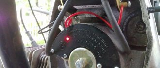
Modification of the generator
This technology for switching to a contactless ignition system is interesting because the motorcycle owner does not need to buy a new generator designed to work in an electronic ignition system. Accordingly, the cost of rework will be minimal.
Enough:
- Make a modulator that will interrupt the circuit;
- And install it on the generator (on the rotor shaft).
A metal plate with a hole drilled in it for a mounting bolt can serve as such a modulator-chopper.
Photo of the only element that you have to make yourself
The modulator installation procedure is as follows:
- The modulator plate (in the diagram below under No. 2) is installed under the mounting bolt;
- Slightly attracted to him;
- By rotating the crankshaft, set the piston to TDC;
- We set the ignition timing;
- Tighten the plate with the mounting bolt.
The electrical wiring of IZH Jupiter 5 remains unchanged when altering the generator.
For reference: in addition to the modulator, two Hall sensors are installed under the engine cover (in diagram No. 1). There are places to attach them.
How to set the ignition?
When setting up the ignition, problems often arise with setting the signal advance angle. A voltmeter will help fix this problem. Looking ahead, it should be said that a device designed for a minimum of 15 V and 10-50 kOhm (internal resistance) is ideal. A voltmeter is connected directly to the terminals. Next, you should bring the piston to the position at which sparking occurs. Then turn on the ignition and turn the modulator until the readings on the device change. You can track the charge on the spark plug by the voltage on the sensor, which should jump. This value is equal to tenths of a volt close to the on-board power supply of the equipment. As soon as the spark is “groped”, you need to fix the position of the modulator directly on the generator shaft. This is usually done with a bolted connection. When adjusting the ignition, constantly short-circuit the high-voltage wires to the frame of the unit. Otherwise, excessive load on the ignition cannot be avoided, which can lead to its failure.