One of the main pain points of heavy Ural motorcycles is the ignition system. Although currently motorcycles produced by IMZ are equipped with Italian-made Ducati Energia electronic ignition, only about three percent of the bikes produced today are sold in the Russian Federation. Most of the owners travel across the country using outdated mechanical ignition in the Ural. Electronic one has a number of advantages.
Modern replacement
This system has been considered outdated for almost half a century. Motorcycle owners often complain about oxidizing and burning contacts, the formation of an oil film, and the need to constantly clean and reconfigure the ignition system. Of course, inquisitive minds have already found a solution to this problem, so installing electronic ignition on the Ural is currently not something extraordinary.
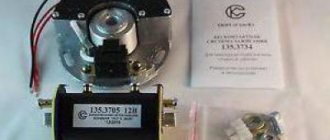
Electronic ignition for the Ural motorcycle is now produced by several companies. The most common models are the SoveK microprocessor contactless ignition system, the Saruman ignition system, the Stary Oskol ignition system and the UKTUS-2 microprocessor ignition. Unfortunately, the last two systems are quite outdated, although they are still popular. In addition, there are a huge number of options for homemade systems. Many owners of motorcycles of this brand make their own ignition for the Ural. Electronic (or contactless) is superior in all respects to the old mechanical model, whose adherents remain only those who support the postulate “the older, the better.”
Examination
If there is any suspicion of problems with the ignition, you should check that it is working correctly. Diagnosis is carried out in the following order;
- We check the mechanical component of the unit. We look to see if the cam mechanism is stuck; if there are problems with mobility, then it is worth checking its performance. Be sure to measure the gap between the cams; most often it turns out to be too small, which prevents sparks from forming;
- The next step is to check for the presence of a spark. To do this, turn on the ignition and force the cams to move using a screwdriver, creating a gap. The spark should be blue and white. If it is red or orange, then you need to look for a malfunction.
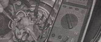
- We take a multimeter and measure the resistance at the bobbin terminals. Attention! The ignition must be turned off. On the primary winding the resistance should be 6 Ohms, on the secondary winding 10 Ohms;
- The resistance between ground and terminals is checked, in optimal condition it should be 6-15 Ohms, if more, then the problem is in the wire;
- The tester is also used to ring high-voltage wires. If the resistance tends to infinity, then it is worth replacing the wire; it is better to do it as a set;
- The last step is to check the condition of the candles. Electrodes should have a sand color. It is recommended to maintain a distance of 0.6 mm between them.
Actually, this is all that should be checked. Microprocessor varieties are also checked in approximately the same way. SoveK ignition is of this type.
MBSZ "SoveK"
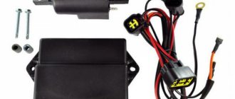
Sovek LLC has developed and successfully implements a microprocessor-based contactless ignition system for heavy Ural-type motorcycles. This option is suitable for those who do not want to bother with homemade units. The manufacturer promises improved starting in cold weather, increased engine stability by reducing spark asynchrony and optimizing the ignition timing, reducing exhaust toxicity, fuel consumption, stable starting even when the battery is discharged to a voltage of 6 volts, as well as preventing overheating of the ignition coil, which was one of the main problems of old systems. The main components are a modulator and a Hall sensor. Installing the SoveK ignition is quite simple, described in detail in the instructions and will take no more than half an hour.
Care must be taken to ensure that the modulator does not touch the Hall sensor. It is also recommended to replace old high-voltage wires with wires with distributed resistance. Reviews from motorcycle owners are rather positive, although some note a slight drop in power. Since the Soviet motorcycle, which needed to replace the contact ignition with an electronic one, has a rather worn-out engine, it is difficult to say how objective these assessments are. But many owners are very pleased that they installed this ignition on the Ural.
Features of the development of electrical equipment for Ural motorcycles
Over the years, the six-volt circuit ceased to meet technical regulations, and on subsequent models, manufacturers installed central wiring designed to operate 12V equipment:
- Rechargeable 12-volt battery;
- More powerful generator;
- Ignition coils;
- Headlights;
- Turning lamps and side lights;
- License plate lamps;
- Brake light lamp;
- Fuse box.
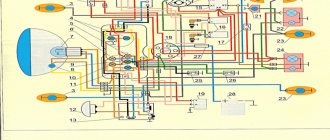
Modern wiring to the Urals M-67 according to GOST 3940-71
For reference: the introduction of GOST 3940-71 for automotive and tractor electrical equipment in 1975 forced the Irbit and Kiev motorcycle factories to upgrade the Ural M-67 and Dnepr MT10 motorcycles to a 12-volt electrical system.
The 12-volt ignition system for Ural motorcycles consists of:
- power sources (battery and generator);
- ignition coils;
- low and high voltage wires;
- spark plugs;
- manual or automatic ignition timing regulator;
- central switch (ignition switch).
Electronic ignition "Saruman"
The Saruman microprocessor ignition system is another way to quickly and without much hassle replace the outdated contact ignition of the Ural. Manufacturers promise the same set of advantages as the previous system. There are two configuration options: with a Hall sensor and with an optical sensor. The second option is somewhat more expensive, but it is usually recommended, since the optical sensor is more accurate and reliable. However, reviews from motorcycle owners are not as good as we would like, mostly complaints are made about the quality of assembly of parts. Another complaint is that the kit does not include an ignition coil.
Homemade electronic ignition system
The ignition for the Ural, electronic or contactless, can be assembled with your own hands. Such systems are assembled by craftsmen from improvised means. The main components necessary for operation are purchased at the nearest car market - a switch, for example, from a VAZ 2108, a Hall sensor and an ignition coil. The latter is often taken from Oka. Additionally, an interrupt modulator is assembled. The reliability of these systems leaves much to be desired, since the ignition timing is not always correctly adjusted in them.
The quality of the interrupt modulator is very important for such systems, but since high-precision tools are not available to many craftsmen, this negatively affects the result. Since for many Ural owners their motorcycle is not so much a vehicle as an object for technical experiments, sometimes very worthy examples appear.
Contactless ignition system for motorcycle Ural, Dnepr
Solving the problem of the reliability of the ignition system on my Ural motorcycle, I came to the conclusion that it was necessary to install a BSZ...
Having considered the huge abundance of options for contactless ignition systems, both on the market and on the Internet, I decided to make for myself the simplest option for the electronic part. Namely, use a Zhiguli Hall sensor and switch. The reason for choosing this particular combination was that I like to travel far and for a long time, and you must admit that if a specific unit specifically for a motorcycle fails along the way, it is not always possible to find a replacement for Saurman or an opto sensor somewhere in the outback, just as it is not always possible to carry it with you contact ignition kit in reserve. And spare parts for Zhiguli can be found in any village.
Search for BSZ kit
So, the choice has been made, all that remains is to implement it. I went to the market. I bought a switch for a VAZ 2108, a Hall sensor and a piece of wiring from a VAZ 2107 distributor. I bought a two-terminal coil from Oka. I also needed an old breaker housing to make a mounting panel for the Hall sensor that I had.
How to make a butterfly for BSZ
The simplest, but not the most correct option was to make a modulator butterfly, ordering it from a turner, which could be rigidly fixed to the shaft. In this case, the ignition timing would remain constant all the time. Of course, it would be possible to add an additional FUOZ unit (ignition timing generator) to this option, but, based on my concept of “reliability in simplicity,” this option also did not suit me. I wanted the engine to work as it should, without complicating the electronic part, so I went to the market again and bought a new Ural cam with a centrifugal regulator. I approached the selection of the cam responsibly and bought the most reliable one, not a Chinese one.
We make a plate for the hall sensor
I took the old body from the breaker, removed all the insides from it, and sawed off the vertical walls to a horizontal plane. The result is a plate like this.
Next, having thought about how to secure the Hall sensor, I decided to “sink” it and secure it at the bottom of the plate, fortunately there was 3 mm of free space under the plate, just right for attaching the sensor. This mounting option seemed to me the most rigid, plus the sensor mounting screws will not be unscrewed due to engine vibrations, since they will rest against the housing. I made the necessary cut in the plate along the width of the sensor, drilled two holes and cut an M3 thread. I installed the Hall sensor on the plate and secured it with M3 screws with countersunk heads.
We manufacture a modulator for BSZ
I measured the vertical distance from the slot in the sensor to the edge of the plate. I got distances from the bottom edge of the sensor slot of 6 mm from the top of 10 mm. I installed the plate on the motorcycle, installed the cam with the centrifugal regulator in place, looked at how the lower edge of the cam sits in relation to the plate, it should be approximately at the same level. I transferred the distance from the plate to the center of the slot in the sensor to the cam body. In my case it turned out to be 8 mm. Marked a horizontal line. The curtains will be welded at this level. I left the marking line for release.
I measured the distance from the center of the shaft on which the cam sits to the Hall sensor housing through the slot - 28-29mm. I decided that the diameter of the butterfly should be 54 mm, so that there would be a gap of 2 mm between the edge of the curtain and the sensor body. Somewhere on the BSZ discussion forums I read that for the switch to work properly, a 2/1 cycle is required. That is, two parts of the sector are closed, one part is open. It turns out 120 degrees metal, 60 degrees slot.
Determined the central axis of the cam. If you look at the cam directly in the center of the hole, you will see that the cam is not round. Only two parts are round, and two seem to have been ground off. The axis passes through the centers of both rounded parts, i.e. where the contacts remain open. Using simple calculations, I marked four vertical lines on the cam. Got clear boundaries of sectors horizontally and vertically.
I ordered a mandrel from a turner - a round metal washer 8 mm thick, 54 mm in diameter and with an internal hole of 22 mm, so that the round part of the cam would fit tightly into the washer, without play. The sectors for the modulator were first cut out of cardboard. I did this with the metal: I cut out a round piece from a 1 mm sheet of iron with a chisel, and drilled a hole in the center for an M8 bolt. I drove a bolt into this hole, tightened it with a nut, inserted it into the drill, turned on the drill and carefully sanded the edges of the workpiece with a file to the desired diameter and shape.
I marked the resulting workpiece into 4 sectors, two at 120 degrees and two at 60 degrees. I carefully sawed one marked side into two halves, put both parts together, and made a cut along the remaining line. Got the required sectors. Next, holding the sectors again in a vice, I made it as on a paper blank, and drank the required shape under the welding site.
After all these manipulations I went to the welder. Well, everything is simple there. We inserted the cam into the mandrel turned by a lathe. We laid the petals on the mandrel, oriented them along the marked lines and welded them to the eccentric. The most difficult part of the BSZ butterfly modulator was ready.
Installing BSZ on a motorcycle
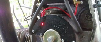
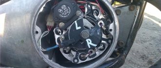
Installation on the motorcycle did not take long. The old ignition had already been removed. In its place I installed a plate with a Hall sensor and put the butterfly modulator in place.
I determined the places where the switch will be located (in my case, near the battery) and the ignition coil (under the front of the tank).
I used silicone wires from the coil to the spark plugs with automobile rubber tips (more than once they helped me out in heavy rain). I ran the wiring to the switch from the Hall sensor, having first lengthened it a little.
I connected the plus of the switch and the ignition coil to the standard wiring wire, which used to go to the breaker, and the minus of the switch to the housing, using the switch mounting bolt. The negative wire of the coil was connected to terminal No. 1 of the switch, as indicated in the diagram. He turned on the ignition and cranked the engine. There was a spark. All that was left was to turn on the ignition.
We set the ignition for the first time with the BSZ butterfly modulator.
We set the ignition almost as described in the manual, but with some adjustments due to the fact that we now have no contacts. The opening moment is determined by the spark on the spark plug when the modulator curtain passes through the Hall sensor.
So. We set the crankshaft to mark P (early ignition, first mark, complete alignment of the arrow on the crankshaft and the marks in the center of the window). We unscrew the spark plug from the left cylinder, put on a high-voltage wire, and provide the spark plug with reliable ground. We move the weights as far as they will go and by turning the body of the plate with the Hall sensor we catch the moment of the spark. Having caught the position of the plate at which the spark jumps, we tighten it with three screws. We check again to make sure that the angle is not knocked down when tightening. The spark should jump at the moment of maximum divergence of the weights. The next step is to check the advance angle on the second cylinder. We rotate the crankshaft 360 degrees (a full turn) until the marks and marks P coincide. And we check for the presence of a spark at the point where the weights are completely separated. (We do not touch the plate with the Hall sensor) If a spark appears at the moment of complete divergence, then you can congratulate you, everything was done correctly.
We bring the modulator to mind.
If, when checking the second cylinder, a spark appeared before the weights reached their maximum or did not appear at all, then the modulator was made out of alignment. In this case, the spark will be in the cylinders at different ignition timing angles. This defect can be removed quite simply as follows.
Let's first figure out why the spark didn't appear. But it did not appear for the reason that the modulator curtain did not open completely and did not go all the way. You just need to help it open, file its edge a little with a file (the one that is located in the slot of the Hall sensor). In order not to confuse the edges of the modulator, we mark the edge that “does not spark” with a felt-tip pen or in some other way and then file it down until a spark appears. (Four strokes of the file were enough for me and a spark appeared).
Now let’s look at the option of a spark appearing until the weights are maximally separated. The curtain opens before the weights reach their maximum spread. It is necessary to reset the ignition on this side of the modulator. We do not touch the crankshaft; it is already installed in the desired position, mark P in the center of the window for the desired cylinder. We unscrew the three screws of the plate with the Hall sensor, move the weights to the maximum and catch the moment of the spark. Got caught? Great. We tighten the plate, check the spark at the maximum spread of the weights. Now turn the crankshaft a full turn until mark P appears in the window for the next cylinder. In this position of the crankshaft we again try to get a spark. It shouldn't exist. We mark this edge of the modulator with a felt-tip pen and work it with a needle file until a spark appears. Now your modulator has been adjusted and the ignition is set to 80 gasoline.
How to set the ignition on a Ural motorcycle for 92 gasoline
If you use the 92nd, then you need to adjust the ignition a little, do it a little earlier. Set the crankshaft to the position where the P mark has just appeared in the window, under the upper edge of the window. In this position, install the ignition.
I’ll add that this season, with this ignition option, my motorcycle has covered about 8,000 kilometers. The weather conditions were very varied from +3⁰ at night to +45⁰ in the heat in the steppes. More than once I had to drive in heavy, prolonged downpours. There was not the slightest malfunction in the ignition system.
Editorial staff of the online magazine “My Automobile.South”
This might be interesting
- On bicycles through the mountains This is a report on a journey by bicycles through the Caucasus Mountains of completely unprepared people. Read this article and you...
- Car loan. Article 5. Reviews about car loans It’s up to you to decide whether to take out a car loan or not. We publish reviews from consumers and car owners who at one time...
- Tuning the Izh motorcycle. BSZ on Izh Jupiter The main “soreness” of the Izh Jupiter motorcycle engine is the standard contact ignition system. Any owner of Jupiter...
Installation
It should be noted that there are quite a few ways to install electronic ignition on a Ural. It all depends on the model. You need to start by dismantling the old breaker and switch located under the saddle. Sometimes it is necessary to replace the ignition coil. Next, a modulator is mounted on the camshaft, a sensor is attached to the cover, and a new switch is installed. All that remains is to adjust the ignition timing.
I’m going to install BSZ, but which is better - Staro Oskolskoye or UKTUS. What are their pros and cons? What are the differences?
dearg, the uktus is better in all respects, except for the price. I drove both. The motor with the Uktus seems completely different after the Stary Oskol one. Much easier to gain momentum. It's all about the automatic OZ.
If I install the UKTUS, will the tachometer from the VAZ-2106 work the same as with a standard ignition or will it need to be redone?