In IZH Planet motorcycles, be it version 3, 4 or 5, the ignition installation in accordance with the diagram must be carried out using the device that came with the motorcycle. But since it is not so easy to find this device today, we will make do with improvised means. Non-contact ignition is configured by adjusting and setting the gap of the distributor contacts. An equally important nuance is the correct setting of the moment of sparking.
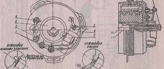
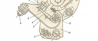
Diagram and designation of parts of the IZH distributor
If your IZH Planet 3 is equipped with a single-cylinder internal combustion engine with a G-36 M generator device, then in this case the procedure for setting the gap is carried out by turning the eccentric, marked in the diagram with the number 1. In this case, bolt 2 according to the diagram must be loosened, and the eccentric itself is turned or right or left. Before setting the BSZ on products from the IZHMASH plant, the crankshaft must be turned. It rotates until the moment of greatest divergence of contacts occurs. It is in this position that the ignition of the IZH Planet 5 is adjusted - you need to ensure that the maximum gap on the contacts is around 0.35-0.45 mm.
According to experts, the ignition system should be adjusted with the cylinder head removed. In this case, the piston itself must be located in a position where it does not reach the dead center; to find out what the clearance should be in this case, you need to use the instruction book. For example, in versions 3 this parameter should be 3.5-4 mm, in Planets 4 - from 3 to 3.5 mm, and in Sports versions - from 3.5 to 3.8 mm. It is in this position that the spark will appear. The adjustment procedure in this case is performed by turning the interrupter assembly, while the bolts marked in the diagram as number 10 must be loosened.
Assembly diagram for IL
Adjusting the ignition, in particular, setting the gaps between the contacts of the interrupter device, should be performed in the following order:
- First of all, the crankshaft is turned by the kick starter.
- One of the interrupting elements is set to the contact opening position. In this case, the bolt marked number 4 in the diagram must be loosened.
- Next, using the eccentric number 3, the gap is set; this figure should be from 0.4 to 0.6 mm. After this, the same actions are carried out with the second pair of contacts.
It should be noted that the entire procedure must be carried out with the candles unscrewed. When you place the dipstick in the corresponding hole for the spark plug in the right cylinder, you need to turn the crankshaft with the kick starter. You need to find the top dead center and having found it, you should make several marks on the dipstick - one of the marks should be placed at the level of the hole, and the other should be located slightly higher - about 2-3 mm. After this, the crankshaft must continue to be turned, this is done until the upper mark reaches the position in which the first mark at top dead center was set (video author - Garage in the USSR).
In this position, the elements of the interrupter assembly, which is located on the lower surface, will begin to open. It should be noted that the procedure for setting the contact opening is done by turning the base, but to do this you need to loosen the bolts numbered 2 and 7. And when you can make the adjustment correctly, these screws will need to be tightened. As for directly determining the moment of rupture, it can be detected thanks to a light bulb, which must be connected in advance to the body ground and the distributor terminal.
After the torque on the right cylinder has been set, the same procedure is performed in a similar way only on the left cylinder. In general, the situation is similar, only in this case it is not the lower, but the upper base that rotates, and in this case, bolts 1 and 7 should be loosened.
Step-by-step guide to installing and adjusting the ignition
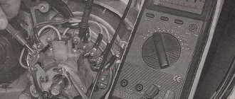
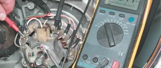
To carry out the setup, you need to prepare a special tool, a tester, and a light bulb with two wires.
A caliper will be needed as a depth gauge. To set the gap it is convenient to use a special feeler gauge. Setting up SZ on IZ Jupiter 5 consists of the following steps:
- First open the generator cover.
- To make it more convenient to work, remove the right cover from the crankcase.
- Using the generator bolt, turn the crankshaft clockwise. It is necessary to ensure that the breaker contacts open to the maximum distance.
- Unscrew the screw a little and turn the eccentric. It is necessary to set a gap between the contacts equal to 0.4-0.6 mm. After this, tighten the screw well.
- Rotate the crankshaft in the direction of movement of the clock hand. The piston should be installed at TDC.
- You need to turn the crankshaft in the opposite direction, that is, counterclockwise. In this case, the piston should not reach TDC; a distance of approximately 3.0-3.5 mm should remain. By loosening the screws, you should establish the beginning of the contact closure. After this, the screws must be tightened tightly.
- To determine if the contacts are open, use a test light with wires. One wire must be connected to the breaker hammer terminal, and the other to ground. After turning on the ignition, when the contacts are closed, the light should light up.
- If BSZ is installed on IZ Jupiter, then there is no need to set the gap. To determine the moment you need to use a tester. The device should be set to measure voltage. The probes must be connected to the 2nd and 3rd contacts of the DC. While the modulator is not in the DC, the voltage reading on the tester should be 7 V. At the moment when the modulator is in the DC, the voltage reading should be in the range from 7 to 0 V. At this moment, a spark is formed.
- The procedure must be performed on each cylinder. It is advisable to start adjusting the gap on the left breaker. When the left breaker is configured, you can move on to the right one.
Ignition adjustment, but let's start with a little introduction.
If now motorcycles from foreign manufacturers predominate on the roads, then literally 20-30 years ago only domestic Izh “Jupiter” and “Planet” rode on our roads. 2 years difference in production, identical appearance, there are not many differences in them, but still Jupiter-5 wins due to its two-cylinder engine and its easier starting.
Main components:
- Two-stroke, two-cylinder 347.6 engine;
- Air or liquid cooling system;
- Automatic clutch release mechanism;
- Drum brakes;
- 18 wheels;
- The steering wheel has a conventional instrument panel (speedometer, ignition lamp, etc.);
- Two shock absorbers. Setting up the ignition on Izh Jupiter 5 must be done in compliance with all rules. To do this, you need to know the exact algorithm of actions when carrying out this event. Therefore, in this article we will describe in detail how to set the ignition on Izh Jupiter-5.
Recovery process
When the euphoria of the purchase wears off, a lot of questions arise regarding its repair and restoration with your own hands.
DIY BSZ on IZH Planet 5
The main task of the new owners:
- Restore the electrical system - and there are no particular problems with this, since the electrical wiring of IZ Jupiter 2 and Planet of the second and third generations is identical and interchangeable;
- Starting the engine is a more difficult task due to the need to overhaul the power unit and the availability of spare parts;
- Return the motorcycle to its original appearance. It is also quite complex and, perhaps, the most painstaking work of the entire project.
The video below shows the restored models.
Izh Planeta 2
Factory layout for several generations of motorcycles
- Whether to switch to contactless ignition or change the voltage from 6 to 12V is up to you to decide.
- If you have such a desire, and you manage to get your hands on a native Izhevsk generator 281.3701, then the replacement process will be much easier.
- The publication IZ Jupiter 3 wiring diagram will familiarize you with the details of the alteration.
central locking
Let's consider the process of restoring the central lock, since in most surviving models it is faulty.
Appearance of the headlights and controls of IZH Planet 2
The difficulty is that finding the original lock is very difficult, almost impossible. Moreover, at 6V, since later the Izhevsk Motor Plant transferred all subsequent models to 12-volt equipment.
This is what the filling of the original 6V ignition switch looks like
Therefore, many motorcycle owners adapt parts from later versions of Planets and Jupiters.
The difficulty of installation in this case is as follows:
- Uncertainty about whether the lock will work;
- How to properly connect wires.
Wiring diagram for IZH Planet 2 to the lock
Headlight
Many owners do not attach importance to adjusting the head light, believing that a working light bulb and intact glass are enough for “driving” during daylight hours.
Using this scheme it will be easy to connect all consumers
Correct ignition settings for Izh Jupiter 5
In fact, this is not so, and adjusting the light is not only desirable, but also mandatory, especially since it can be easily done independently, spending no more than half an hour of personal time on it.
Scheme for adjusting the angle of luminous flux
Electrical circuit of the Voskhod motorcycle
Features of setting up a starline car alarm
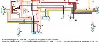
Central switch. 2. speedometer. 3. Speedometer light. 4. Headlight. 5. Headlight lamp. 6. City driving lamp. 7. Sound signal. 8. Direction indicator lamp. 9. Direction indicators. 10. Direction indicator switch. 11. Electronic switch. (D - sensor terminal, K - ignition coil terminal, G - generator terminal.) 12. Throttle. 13. Relay breaker. 14. Generator. 15. License plate lamp. 16. Brake signal lamp. 17. Rear light. 18. Wire connection block. 19. Brake light switch. 20. Shielded spark plug cap. 21. Spark plug. 22. High voltage wire. 23. Ignition coil. 24. Light switch.
Wire colors: sn. - blue, cf. - gray, g. - blue, g. - yellow, h. - green, k. - red, kor. - brown, op. - orange, f. - violet, h. - black.
The generator is good, but it needs to be rewound to 12V, otherwise the wiring will have to be redone a lot and the battery will not be able to be made into the lighting circuit; all the lamps except the neutral lamp and the 12V control lamp are easier to find than original ones. The faceplate was made according to drawings by Dmitry67:
The generator flywheel was not mounted as in the article, but as it should be - on a key. Of course, the rotor is 3 millimeters deeper than it should be, but everything works as it should
Article - “Does the Planet Need a Battery?” - have already been posted. This is right. It all started with this article for the majority of current users of such modifications.
However, there were earlier versions. I'll post one more to complete the collection. From the book of Boris Fedorovich Demchenko »
There are some mistakes there.
I converted several IZh motorcycles to Voshodov ignition (IZH 56, IZH P 3, IZH P 5, IZH PS, IZH Yu 3, IZH Yu 5.)
In the process of this work, optimized drawings of adapters were developed. The preferred material is alloy D 16. It does not rust - it is easy to process and holds the thread normally. If there are no suitable aluminum alloys, plain steel will do. The only negative is that it can rust. I don’t recommend stainless steel - it’s difficult to process it later on site. Drilling is also vicious. I tried to make one adapter from hot stainless steel - I did it but cursed everything.
Briefly speaking. The installation of the IZH generator 6 volt and 12 volt is different. Accordingly, different adapters are needed, depending on the motor model.
Drawings of blanks for a turner:
During manufacturing, it is advisable to sharpen the adapter from one installation. That is, at the end of processing it should be like a ready-made adapter - attached with the narrow end to the blank. And then they cut it off from the blank and trim the cut edge. This will create a part without compromising the wall thickness.
A little later there will be a continuation. This is not all I wanted to write yet.
how to set the ignition on Jupiter 5 | Topic author: Valentina
Features of self-adjustment of headlights on a gazelle
Diana According to the instructions.
Maria According to the instructions. Do you think someone wants to copy two printed sheets with instructions here for you?!
Vadim 2.6 mm to TDC opening of the contacts - the 12 V light bulb is on - this means the beginning. You need to connect the light bulb to the breaker contact and turn on the ignition and turn the crankshaft if I remember the key is 11
Alexandra First, you set the gap on the Liliya breakers; to do this, you turn the crankshaft by the head of the Egor rotor mounting bolt. You determine the maximum opening of the contacts and set the gap to 0.6-0.8mm. Next, you will need the Stepan bushing and wrench from the Anastasia motorcycle key set. You start adjusting the timing from the right cylinder Anatoly. You install Stanislav instead of the spark plug of the right cylinder!), lower the knob into it, and turning the same rotor bolt you find TDC Inna That's it, stop! By turning the sleeve to unscrew, you align the cut of the sleeve with the notch on the collar. Now you need to lower the piston two notches below TDC Anton You return to the breaker. You unscrew the three screws on the crossbar securing the breakers and move them slightly counterclockwise, the contact opens. If you have a battery, you can connect a 12v 1sv light bulb directly to the wire on Valery’s breaker; if you don’t have a battery, we use *tissue paper*. So the piston is lowered below TDC by two notches, i.e. 2.5 mm, if memory doesn’t fail us, don’t turn it anymore!) The moment has come to find the beginning of the breaker break, and the light bulb will tell you about it. By moving the lower joint of the breaker traverse clockwise, the light goes out and lights up counterclockwise. So you need to capture that moment when the light bulb lights up! Lights up, fix the lower screw of the traverse. The left cylinder is adjusted in the same way. Now about the tissue paper. It is used as an indicator to determine the beginning of a rupture. We install it between the contacts of the breaker and determine the beginning of the break by free movement when the traverse moves.
I always set Victor by eye) 2mm to top dead center with a feeler gauge, and the contact gap by eye is a third of a millimeter. It worked flawlessly, the cylinders did not fail, I set it up and drove it for a year until I sold it. but it depends on experience. try to set it in different ways, gain experience, then you can also set it by eye when you get better at it) in the days of Jupiters there was no Internet, they set the ignition by trial and error
Installing a contactless ignition system on Izh Jupiter-5 is a fairly current topic. When setting up a BSZ on Izh Jupiter-5 BSZ, it is necessary to take into account a number of nuances that can significantly affect the operation of the equipment used.
What advantages open up to users who decide to install electronic ignition on the Izh Jupiter are described below.
Most modern motorcycles are not equipped with cams, that is, breakers. Why did the manufacturer consider them unnecessary for currently sold models? The answer is quite simple. This system is not very reliable.
Many parts used in the system are sources of trouble. The most common ones are listed below:
- The ignition gaps change their original position while driving a few days after adjustment;
- A spark occurs every once in a while, since the contacts regularly burn out;
- Capacitors are constantly damaged;
- Low spark power;
- If you add two or three volts to the battery, it is quite difficult to start it. Such ignition is the reason for constant repairs while driving.
This is noticeable at idle. The speed of their passage has noticeably increased and the unnatural twitching has disappeared. The characteristic knocking sounds of iron components in the crankcase and accompanying detonations also disappeared. The handling of the Jupiter 5 motorcycle will improve simultaneously with the time it takes to gain speed.
Maintenance Features
Features of the gsm module for car alarm starline a93 and instructions for installation and configuration with your own hands
Often during operation it is necessary to correctly set the gap between the contacts of the breaker. To do this, you need tools and a diagram to see which elements need to be dismantled.
The algorithm of actions is as follows:
- place the motorcycle on the stand;
- turn on neutral;
- unscrew the spark plug from the cylinder;
- remove the engine crankcase cover;
- turn the crankshaft until the contacts are as open as possible;
- using a screwdriver, loosen the locking screw;
- using a special feeler gauge, set the gap to 0.35-0.45 mm and fix it with a screw;
- we collect everything in reverse sequence;
- turn on the ignition and start the engine. Its stable operation at idle indicates that the adjustment has been correctly performed.
In general, all the wiring of IZH Planet 5 is very easy to do with your own hands.
The need for such work often arises when operating a motorcycle:
- in wet weather, driving in the rain for a long time (oxidation or dampness of electrical contacts);
- when traveling over rough terrain, replete with vegetation and bushes (mechanical damage to wiring);
- when used in winter (snow and slush stick to the wires and can damage them).
Often the sound signal suffers during operation. Its malfunctions manifest themselves in the form of deterioration in sound quality.
To restore its functionality, you must perform the following procedure:
- loosen the locknut using an open-end wrench;
- turn on the ignition;
- press the button to turn on the sound signal;
- use a screwdriver to adjust the tone;
- repeat the procedure until we get a clear and loud sound;
- tighten the control nut.
Conclusions: we are confident that this article will help you in servicing motorcycles of the IZH family (see also the article on the IZ Jupiter 5 wiring diagram). Both the attached diagrams and description will help you avoid making mistakes during operation.
Actually the wiring diagram of IZH Planet-5 itself. (you can click to enlarge)
Explanation of the scheme:
1,4,10,2 — Motorcycle turn signal lamp2 — Headlight3 — Instrument panel5 — Handbrake brake light switch6 — Right switch7 — Foot brake brake light switch8 — Turn signal breaker relay9 — Receiver-regulator unit11 — Rear light13 — Battery14 -Fuse15-ignition coil16-light of ignition17-cap of the spark plug18-contact neutral in the gearbox19-switch Left 20-sound signal21-generator22-Locking system valve-the valve-sensor of the lubricant24-flashlight of the backbart trace of the front trailer25-the signal of the front side bitch 26- Turn rear side trailer27 - Rear brake light of side trailer28 - Rear light - side trailer marker light
Generator
The heart is the generator (sometimes called a magneto, but they were never used on Izh Planet). Three windings produce alternating current. For excitation, an additional coil is used instead of a permanent magnet. Therefore, it is impossible to jump start a motorcycle with a completely dead or missing battery.
A diode bridge for current rectification and a voltage regulator assembled in one unit are mounted on the Izh Planet 5 generator (they are not even highlighted in the Izh Planet wiring diagram manuals).
Possible breakdowns in this unit:
- It is checked by measuring their resistance of current-carrying conductors and insulation. If the generator is damaged, it will become noticeably hot.
- — the output voltage will differ significantly from the nominal level or be absent.
- Although the electrical circuit includes short circuit protection, it happens that the automation does not work and most often the output transistor burns out.
Setting the appropriate options
Setting up the BSZ on Izh Jupiter 5 also requires special attention. The ignition is turned on with the tachometer connected. After thirty seconds, indicators of 3000, 4000, 5000 rpm should appear on the device panel. If they are present, then the switch is working correctly.
In other cases, you should pay attention to previously grounded candles. We insert a screwdriver into the hall connector, and then pull it out
A spark should appear on the spark plugs. If it was not possible to cause a spark using the steps described above, then the reason for the incorrect operation is incorrect connections.
The setup looks like this. The dial indicator is unscrewed and the cylinder piston is adjusted. Having connected the voltmeter to the second and third connectors, you need to start rotating the modulator axis. After a jump from 7 to 0.1 volts is detected, the modulator must be secured with a nut. Usually the required advance angle is set.
The test run should be successful if you install the components yourself according to the instructions. Now you can use BSZ.
The main problem with the Izh Jupiter motorcycle engine is the standard contact ignition system. Any owner of Jupiter sooner or later faces the problem of failure of one of the cylinders due to a change in the gap in the contacts or failure of the capacitor. Adjustment helps, but usually not for long. This problem can be radically solved by installing a contactless ignition system on a motorcycle.
Single-channel BSZ.
There are probably many options for BSZ design, but we won’t consider them all. Let's focus on the simplest, and probably the most common option in our country. There is no motorcycle market or motorcycle store nearby where you can buy a factory-made BSZ, and there is no turner with a machine nearby either. We will proceed from this.
Minimum set for installation
But we can’t do without a minimum set, so before you start work, you need to stock up on the following components, which are sold in any auto shop or car market in our country:
1. Switch from VAZ 2108
2. Hall sensor from VAZ 2108
3. Set of wires for BSZ from VAZ 2107 (from distributor (Hall sensor) to switch)
4. Two-terminal ignition coil (from an Oka or Gazelle car with a ZMZ 406 engine)
5. Two automotive silicone high-voltage wires of the required length with caps for spark plugs (you can buy a kit for a VAZ and take it from there, you can simply find used wires, after first making sure they are working)
Next, in addition to the components, we will need a small flat piece of sheet steel 1-1.2 mm thick to make a modulator and a plate for the Hall sensor. I warn you right away that stainless steel or non-ferrous metals are not suitable for the manufacture of the modulator, since they are not magnetic materials. To make a plate for the Hall sensor, you can use any material of sufficient strength.
Tools you may need are a drill with drills, files, a chisel, a hammer and other tools that, as a rule, are found in any garage.
Rework process
We dismantle the old ignition system. We remove the plate with contacts, capacitors, ignition coils with high-voltage wires from the motorcycle. We install the switch in the right glove compartment.
We attach the ignition coil to the frame under the tank. We connect the wiring connector to the switch, connect the black ground wire from the connector to ground. We connect the wire from terminal No. 1 of the switch connector to one of the coil terminals. We connect the second terminal of the coil to the old wiring, to the wire to which “+12V” is supplied when the ignition is turned on. In the old wiring, this wire connected both ignition coils. From it we pull an additional “+12V” wire to the switch, which we connect to the 4th wire in the connector. We carefully isolate everything. We insert the wire with the connector to the Hall sensor into the cavity of the generator.
You can check the functionality of the system. We connect the Hall sensor to its connector, connect the high-voltage wires to the coil and to the spark plugs. We provide reliable weight to the candles. Turn on the ignition and pass a metal object (you can use a flat screwdriver) through the Hall sensor slot. The spark plugs should spark. The scheme is working. (If there is no spark, then something is connected incorrectly and everything needs to be checked again.) Now it remains to supply a spark at the right time to the cylinders, for this:
Improving the standard system
For those owners who do not want to switch to a contactless ignition system, there are other ways to improve sparking.
At the same time, the wiring of the IZH Jupiter 5 motorcycle is analyzed for problem areas, and most often:
- The primary circuit from the battery to the coil is diagnosed;
- Locations of voltage reduction caused by operating conditions are identified.
A simple inspection of the primary circuit will demonstrate several problem areas at once:
- four plug connectors;
- emergency ignition switch;
- central switch contacts;
- breaker contacts.
Under ideal operating conditions, such a complex section of the chain will work flawlessly.
But in practice, it is exposed to dust and dirt flying from under the wheels, so in the circuit due to the increase in resistance at the contact points:
- the voltage decreases from 12 V to 7-8 V;
- this is not enough to excite a powerful discharge in the secondary winding of the coil;
- as a result, a low discharge on the spark plug, making it difficult to ignite the combustible mixture in the cylinders.
And if you add to this a dead battery and oily spark plugs with burnt contacts, then the sparking process becomes completely problematic.
Motorcyclists solve such defects as follows:
- traditional soldering. The wiring on IZH Yu5 gets rid of plug connections and each wiring is soldered manually, followed by insulation;
- installation of an additional toggle switch (in diagram No. 1), which turns off all consumers at the moment the engine starts. This allows the maximum voltage from the battery to be supplied to the coil;
- alteration of the ignition switch. A wire is soldered to the free connector of lock 4 (in diagram No. 2), the second end of which is fed to the positive terminal of the coil. The standard ignition wire from terminal 5 is transferred to terminal 6 and when this key position is activated, a simplified power supply circuit from the battery to the primary circuit of the coil is activated.
Conclusions: from this article you can learn not only tried and tested methods for improving the electrical part of a motorcycle (as in the article about the electrical wiring of the Java 350), but also watch video materials that clearly demonstrate the algorithm for modernization work.
Required Parts
In order for the ignition system to work correctly, a number of auxiliary parts are required. They are listed below:
- Switch for BSZ VAZ cars. You should not choose exclusively from the low price segment. The Astro switch has a lot of positive reviews;
- Hall Sensor. The best option for Jupiter 5 is a similar manufacturer VAZ. By purchasing it in branded packaging, you protect yourself from counterfeits;
- Ignition coil with two terminals. You should choose between the gazelle engine number 406 or Oka with an electronic ignition system;
- A pair of silicone armor wires with rubber caps;
- The modulator is a butterfly-shaped plate made of iron.
Modulator
The most difficult stage is the production of the modulator
It is important to maintain the required shape. The more reliably the required dimensions are observed, the lower the likelihood of problems occurring after implementing the system, that is, there will be no need to adjust it using a file
The ignition timing must match on any cylinder used.
The bolt hole must be located in the middle. Otherwise, the engine operation will not be synchronized. It is also recommended to check the integrity of the crankshaft bearings. If you find defects, you should immediately replace it.
The contact ignition is not able to work normally if the bearings are damaged. The thickness of the part should not exceed one and a half millimeters. If it is thin, it will not be possible to avoid deformation, and if it is thick, it will come into contact with the surface of the hall sensor housing.
To create the plate, it is allowed to use any material except steel. Aluminum and others should not be used as they are not magnetic. The drawing that must be followed can be found in the public domain. The presented diagram will be useful to those people who decide to modernize the vehicle ignition device. Below are methods for installing electrical ignition devices in Jupiter.
It must be turned by a professional turner. He will make a simple disk and draw on it the markings of elementary distances between the corners. Then, in accordance with it, you will cut out the necessary sectors at home. The cost of the modulator is seventy rubles.
It is not advisable to use an ordinary plate, since its width is less than twelve millimeters. This will not be enough to fully accumulate the energy resource in the coil. Of course, it can be installed, but achieving four thousand revolutions per minute will become impossible.
In addition to the above you will need:
- A stud with an applied thread of seven millimeters, pitch 1, as well as a pair of nuts with washers of the corresponding parameters. The priority material for these components is brass. This is explained by the least magnetization of the plate from the generator rotor. If you use a standard bolt, then difficulties may arise with the introduction of ignition. The bolt tends to follow the modulator as it is tightened. However, it is necessary to observe the leading indicator, maintain the same position of the rotor and modulator, and tighten the bolt. It is advisable to use a pin, since many are not able to perform all the necessary actions in total;
- A set of wires with connectors for ignition without contact from VAZ. This part can be purchased or made with your own hands.
Final actions
You should put rubber caps on the armor wires, and insert the latter into the candlesticks or coil above. If you skip this step, the motorcycle will stall when riding in rainy weather, as moisture will get into the battery.
By inserting spark plugs into the tip, it will be possible to maintain excellent contact between the battery and the volume of the vehicle. Now you will need a pre-purchased set of wires. The switch, coil and hall sensor are connected by wiring. She needs to be isolated. Of the entire mass, only a common plus is required.
FORGET ABOUT THE BATTERY
Motorcycles of the Izh and Java brands can be quite easily converted to batteryless ignition. I did this seven years ago and still have no complaints. What is necessary? If the motorcycle has 6 V electrical equipment, then the 7 V generator set is from Minsk or the old Voskhod (with contact or electronic ignition); if at 12 V, then at 14 V - from the new “Voskhod”. Moreover, generator rotors can be either with removable or non-removable cams (in the first case, the installation procedure is simpler). For 2-cylinder engines (with electronic ignition), an additional sensor coil and another electronic switch will be required. Finally, the adapter flanges are turned from steel on a lathe and filed by hand, with a configuration depending on the brand of motorcycle.
The conversion sequence is as follows. First, the old generator with the relay-regulator and capacitors is dismantled, and the key is removed from the crankshaft.
Then a new generator is prepared for installation. To do this, it is somewhat modernized: the key is removed from the removable rotor cam (if it is left, the rotor will be installed as with a non-removable cam), and one of the mounting ears is cut off from the stator, since it will interfere with the crankcase protective cover. Thus, for example, in a Java with 6 V electrical equipment, the stator is attached to the flange with only two M5 bolts.
The generator stator of a 2-cylinder engine undergoes a more significant modernization: in order to place the second sensor coil, a special socket is cut out opposite the first (it is best to do this during adjustment).
Before assembly, for subsequent convenience of fixing the stator, the top dead center (TDC) of a single-cylinder or right-hand piston of a 2-cylinder engine is roughly determined and the adapter flange is attached to the crankcase.
On the crankshaft axle, if the crankcase protective cover fits snugly, place and center the rotor of the new generator while turning the crankshaft (the spark plugs are removed to make it easier). First tighten only the installed standard axle bolt to the end. To prevent the crankshaft from spinning at this moment, turn on the gearbox and jam the rear wheel (put, say, a hammer handle into the spokes).
Adapter flange for motorcycles “Izh-P-Sport”, “Izh-P-4, - 5”, “Izh-Yu-4, - 5”.
Adapter flange for a Java motorcycle with 12 V electrical equipment.
Modification of the generator stator.
Electrical wiring diagram for connecting a new 2-cylinder motorcycle generator:
1 - generator stator, 2 - ignition switch, 3 - electronic switch units, 4 - ignition coils, 5 - spark plugs.
Having secured the rotor, determine the moment of spark formation, that is, the position when the piston in the Java-350 engine does not reach TDC by 2.8...3.3 mm, Java-250 - 3.3...3.7 mm, single-cylinder “Izha” - 3.0...3.5 mm, 2-cylinder - 2.5...3.1 mm (in this position, the groove on the rotor should be aligned with the protrusion on the frame of the sensor coil, and the gap between them should be within 0 .3±0.05 mm). Then the stator is finally fixed.
The piston of the left cylinder on 2-cylinder motorcycles is adjusted in a similar way. Apply the second sensor coil to the stator so that the protrusion of its frame is located opposite the groove on the rotor. Mark the socket, cut it out and fasten the coil with screws, maintaining a gap of 0.3 ± 0.05 mm.
For a complete set on a converted motorcycle, a sound signal and a turn relay from Minsk or Voskhod, operating on alternating current, are used.
Connect the new generator according to the diagram shown. In this case, old electrical wiring is used. The switches are installed in the box where the battery was located.
And one last thing. The circuit does not require maintenance during operation and is configured once - during installation.
S. MYROV
We recommend reading
- STEEL DRUMS Every day we use a huge number of things and have almost stopped noticing them. But it turns out that in the production of seemingly insignificant things there is a lot hidden...
- AND FLOWERS HAVE THEIR OWN HOUSE In houses with thin walls, the window sills, as a rule, are a narrow board, on which only a matchbox will fit. That’s why we have to build shelves, stands and…
Here you can evaluate the author's work:
TWO SHEETS OF PLYWOOD AND A DOORBOARD
More... Subscribe
Wiring Problems
Practice shows that if the motorcycle was stored in a dry garage and was not subjected to dubious alterations, then the Jupiter 5 wiring diagram lasts a very long time. From time to time you need to change some consumables, such as lamps and ignition coils, but otherwise it functions quite stably. However, this is not always the case and problems do occur, for example:
- wire breaks;
- electrical circuit short-circuit;
- failure of their individual branches of the circuit;
- weak light from incandescent lamps;
- incorrect operation of indicators;
- misfire;
- reduction in engine power;
- complete failure of the system.
The problems described above can arise both due to natural wear and tear of wiring elements, and after incompetent intervention in the circuit. There is no universal solution to the problem in this case, and in order to find out what caused the breakdown, you should be patient and have some basic knowledge of the technical part of the motorcycle. First of all, you should get a multimeter or assemble a primitive network indicator using a 12-volt light bulb to “ring” the wiring for breaks. Having found a circuit node that is not working correctly or a wiring break, it will need to be eliminated, the network’s functionality re-checked, and so on, until operation is completely restored.
Ignition adjustment
First you need to determine which contact is used for which cylinder. Set the contact gaps to 0.4 millimeters; if the cam is very worn, reduce the gap to 0.3 millimeters. Next, unscrew the spark plugs and set the piston in one cylinder to top dead center. Insert any clean stick instead of a candle and make a mark. Measure 3 millimeters from this mark and align the piston to the new mark. Using a screwdriver, loosen the contact plate of this cylinder. Insert tissue paper between the contacts and turn the plate counter-clockwise until the paper can be pulled out. Instead of paper, you can connect a light bulb, one wire to ground, the second to contact. Rotate the plate until the light comes on. The second cylinder is adjusted in the same way as the first.
After all the procedures, all that remains is to add oil and gasoline, the motorcycle is ready for use. Correct wiring is the key to long and flawless operation of the Izh Jupiter 3.
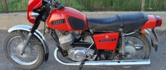
Motorcycle Izh Jupiter 5 - technical specifications and photos
Soviet motorcycles today are considered valuable transport, because back then they produced really high-quality and fast equipment. The Izh Jupiter 5 motorcycle is considered one of these legends of the USSR.
The Izhevsk plant produced several models, including Planet 5 and others. But Jupiter 5 was remembered primarily for its unpretentiousness on roads and maneuverability. With its small dimensions, the model was able to achieve low fuel consumption.
pros
- powerful engine;
- sharp at start;
- spare parts for Izh Jupiter 5 are inexpensive and available;
- soft suspension;
- low cost;
- has 2 cylinders.
Minuses
- weak front fork;
- requires good ignition settings;
- high fuel consumption;
- Motorcycles today require frequent repairs.
Technical characteristics of Izh Jupiter 5
The design of the motorcycle was created in such a way that in the end Izh could ride equally comfortably both on the highway and on uneven roads. Unlike its brother IZH Planet 5, this model had 2 cylinders, which means more power. Also, the owner of the motorcycle could start the engine more easily, which is explained by the absence of the leg returning when started.
Review
Classic transport has always been valued since the USSR, and 20 years ago Jupiter 5 was one of the best.
Today, most riders ride foreign fast motorcycles, but occasionally you can meet a former legend of the 80s and 90s.
In those years, only his brother Planet 5 competed with Jupiter, but he could not compare with the motorcycle in terms of characteristics. Their main difference was the difference in cylinders, and therefore power.
If we continue to compare these two competitors, we can highlight the fact that both models had almost the same data.
For example, they had one tubular frame, and a special subframe was installed to better secure the rear wheel.
In general, the entire design of Jupiter 5 was quite standard and simple, the engine was attached to the frame, the fuel tank was located above, and the headlight and dashboard were installed on the steering wheel.
There were also 2 exhaust pipes installed that ran through the entire motorcycle. Sometimes the pipes got hot and could cause a burn, but the manufacturer installed them below the footpegs to keep the passenger as safe as possible.
Even the first models of the Izh Jupiter 5 motorcycle had simple drum brakes with a mechanical drive, but subsequent modifications received a front disc brake with a hydraulic drive.
Motorcycle appearance
When the Jupiter 5 model came out, its design was already well-known, because it was inherited from the Jupiter 4 motorcycle. But soon the Izh Planet 5 appeared on sale, and the developers saw that they could borrow several design elements.
The first modification had a square-shaped dashboard, which consisted of several indicators, an ignition switch and a speedometer. But soon its appearance was redesigned, and instead of one dashboard there were two. On the first part they placed warning lamps, and on the second part they decided to put a speedometer.
The design of the fuel tank has also been slightly redesigned, with rubber pads on the knees and the shape of the tank itself has become slightly different. Accordingly, in the new modifications of the Moto Izh Jupiter 5, it received a different, longer seat that ended at the brake light. This innovation is still considered stylish and modern.
Being a workhorse, the motorcycle had a fairly sporty appearance and excellent top speed. With a power of 25 hp. the motorcycle could accelerate to 120 km/h.
This is a completely standard indicator, because another representative of the Dnepr could give a maximum speed of 110 km/h. In severe frosts down to 30 degrees, the unit started up perfectly, which cannot be said about the current new products.
Unfortunately, many owners complain of frequent engine breakdowns due to their long lifespan.
Price
Today, a motorcycle of this model is not so difficult to find; in Soviet times it was bought in large quantities, so today you just need to find out how much the Izh Jupiter 5 costs. Of course, the price depends on the condition, because over such a long period many parts could become faulty.
Even during the release of the Izh Jupiter 5 motorcycle, its price was quite high - 1,050 rubles. But this did not stop buyers; they wanted a comfortable and fast motorcycle, which was the best then. But still, compared to other motorcycles, this model had a relatively low price. For example, then new Ural motorcycles had a price of 1,870 rubles.
If you want to buy a legend of the USSR today, be prepared to pay 55,000 rubles for a new motorcycle. Yes, they are still being reliably produced. If this price is too high for you, buy a used model - its price ranges from 5 to 40 thousand rubles.
What is the value of this model
Such increased attention to the IZH Planet 2 model is caused by the fact that:
- in total, just over 246 thousand were produced;
- and there are few surviving copies left;
- which only increases its value among collectors .
According to Izhmash, only 246 thousand Planet 2 models were produced throughout the USSR
Therefore, it is a great success to find preserved motorcycles in garages and sheds of villages and towns (as in the photo below). Moreover, if the previously discussed price has not changed, and the owners give you a bag of spare parts in addition, consider that you have hit the “jackpot” .
Fortunately, you can still find “live” IL with original parts. True, only in this state
Technical specifications
- Overall length 2,115 mm.
- Overall width 780 mm.
- Overall height 1,025 mm.
- Ground clearance 135 mm.
- Dry weight of the motorcycle is 160 kg.
- Maximum speed 110 km/h.
- Fuel tank capacity 18 l.
- Cruising range on the highway is 160-180 km.
- Fuel consumption on the highway is no more than 4 liters per 100 km.
- Fuel: Gasoline with autol 10-18 in a ratio of 25: 1
- Fordability 300 mm.
- Engine Stroke 58 mm
- Cylinder diameter 61.75 mm
- Number of cylinders 2
- Engine displacement 347 cm3
- Compression ratio 6.8
- Maximum power 18 hp. With.
- Air cooling
- Lubrication system combined with fuel
- Carburetor type K-28ZH
Multi-disc clutch, in an oil bath with an automatic release mechanism. The gearbox is four-speed, two-way. Motor transmission is a rollerless double-row chain, gear ratio - 2.57. Transmission from the gearbox to the rear wheel is a roller chain, gear ratio - 2.33. The frame is tubular and welded. The front fork is a telescopic spring type with hydraulic shock absorbers. Rear suspension pendulum spring with hydraulic shock absorbers Type of brakes drum Type of wheels easily removable, with tangential straight spokes. Tire size 3.25-19″
Differences from the second Planet
For many modern citizens, the information that domestic motorcycle manufacturers worked tirelessly to improve their models in an era of total shortages may come as a surprise.
Note! The fact takes place, moreover, it is supported by official documents, in particular 1970N04P16-17 - this is the outgoing number of the factory newsletter, which described the changes made.
In the photo - official materials of the Izhmash Design Bureau
The new generation motorcycle received:
- Direction indicator lights are a first in domestic practice;
- Semiconductor relay for controlling direction indicators (installed in the headlight);
- New size of wheels and tires (3.50x18 versus previous - 3.25x19);
- New brand increased capacity battery (old one on IZH Planet 2 - ZMT-6);
- And, of course, more engine power. The power unit now developed 18 hp.
Modifications
But the creator engineers did not stop there and, having released the five-millionth car from the production line, presented a modification of the IZH Planet 3-01.
Mirror and safety arches are the distinctive features of the new modification
Among the innovations it should be noted:
- Rear passenger footrests;
- Roll bars;
- Rearview mirror;
- New steering wheel design.
For reference: The buyer paid for the changes out of his own pocket. In particular, the price for IZH Planet 3-01 was 750 rubles, the version with a stroller was 1140, and the “rural version” was even more expensive. Fortunately, care instructions were included with purchase, which made maintenance easier.
IZH Planet 3-01 with wide wheels of smaller diameter - “rural version”
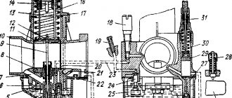
Adjusting the K-68 carburetor on the IZH Planet-5 motorcycle
The K-68I carburetor was installed on the Izh Planet-5 motorcycle more often than others. With proper setup and proper care, the motorcycle starts quickly, runs smoothly and without complaints.
To adjust the K-68I carburetor you will need a flat-head screwdriver, pliers, and a ruler. For clarity and ease of adjustment, use the K-68 carburetor diagram.
Algorithm for adjusting the Izh Planeta-5 carburetor:
- The first step is to check the fuel level in the float chamber. Unscrew the camera cover bolts with a screwdriver and remove it. Turn the carburetor over and use a ruler to measure the distance from the carburetor body to the top edge of the floats. It should be 26 ± 5 mm. If the parameters deviate, the tongue of the floats is bent in the appropriate direction using pliers. At the same time, in no case should the parallelism of the floats be disrupted.
- Set a gap of 2 mm between the throttle valve and the bottom of the mixing chamber by adjusting screw 11. Then check the position of the throttle needle. The required needle position is the middle groove. The remaining grooves are made to move the needle lock and adjust the appropriate fuel quality depending on climatic conditions.
- After all the above steps, we proceed to the most important stage - setting the idle speed. The idle quality adjusting screw 15 (located vertically on the left side of the carburetor) is screwed in until it stops, and then unscrewed 1-1.5 turns. Start the engine and warm up for 5 minutes. Using the mixture quantity adjustment screw 11 (located horizontally on the left side of the carburetor), we set the minimum stable engine speed. At the same time, slowly unscrew screw 15 until the engine speed stops increasing. It is the moment of reducing the crankshaft speed that will be optimal for determining the position of the adjusting screw 15. We again reduce the engine speed with screw 11 and unscrewing screw 15, we find a new optimal position of the throttle valve. This operation must be repeated until the minimum, but at the same time stable, engine crankshaft speed is established.
- By sharply turning the throttle lever at idle, we check the correctness of the adjustment (the quality of the mixture). If, when the throttle is opened sharply, the engine stalls or picks up speed poorly, screw 15 needs to be tightened a little, thereby enriching the mixture. If the engine stalls when the throttle is closed, screw 15 should be unscrewed slightly.
- You can also check the correctness of the adjustment by the color of the central insulator of the spark plug. After adjusting the carburetor, drive a motorcycle for a distance of 5-10 km and remove the spark plugs from the cylinder head. Dark carbon deposits indicate that the mixture is too rich. A light color (whitish or sandy) indicates that the mixture is poor. The normal recommended candle color is brown or brick.
- It is also worth remembering that the free play of the throttle cable is 1-3 mm. If it is not there, the throttle adjustment will be incorrect. The free play is set by adjusting a special bolt located under cap 18.