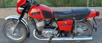
Many motorcyclists, despite the enormous selection of modern motorcycle equipment offered by foreign companies, prefer Russian-made brands. One of the popular models of two-wheeled vehicles among domestic buyers to this day remains the IZH motorcycle, which was produced at the automobile plant in Izhevsk from 1987 until 2008.
The Izh Planet 5 motorcycle, the production of which took place during the years of perestroika, was intended primarily for use on hard road surfaces. The model was equipped with an electronic engine starting system. Therefore, for a long time, the motorcycle was in greatest demand among representatives of the middle income level. At the same time, some motorcycle equipment was manufactured with not quite modern contact breakers, due to which many owners of such “bikes” often encounter problems setting up the ignition of the Izh Planet 5 motorcycle.
Izh planet 5 adjust the ignition
Izh Planet 5 is the brainchild of the Izhevsk Machine-Building Plant. Its production was discontinued in 2008, and the model itself entered the assembly line back in 1987. Accordingly, in any case, the bikes that are traveling on our roads are far from brand new. But they are reliable in service, so we will see this model on our roads for many more years. Izh Planet 5, the ignition adjustment of which is described below.
It goes without saying that with age, any technology develops certain problem areas. Izh Planet 5, in principle, does not create extremely problematic situations for its owner, but it does have a weak point - ignition.
In order to figure out how to adjust the ignition on Izh Planet 5 and be able to fix the problem yourself if necessary, you need to have a certain tool, time and a little optimism. The first time it may be a little difficult, but as they say, the master’s work is feared.
First you need to remove the crankcase cover, but you can get by by removing only the generator cover. In the first case, it will be more convenient to do subsequent work.
The tool you will need is a caliper or a feeler gauge, but in the absence of such, you can make an analogue of a depth gauge using a handy tool (screwdriver), the feeler gauge is needed to measure the gap.
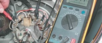
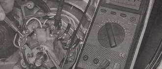
We connect the control light to the terminal. We turn the spark plug out after turning on the ignition. We take the crankshaft by the generator bolt and turn it in the direction of movement of the clock hand until the moment when the breaker contacts are maximally open, after which you should loosen the screw, turn the eccentric and set the intercontact gap to approximately 0.5 mm.
Tighten the screw. We lower a caliper micrometer (or its equivalent) into the cylinder. Carefully turning the crankshaft, we find the top dead center (TDC) by performing rotations in the direction of movement of the hand on the clock. We fix or mark this position on a micrometer (screwdriver). Let's measure and record a 3.5 mm mark on the micrometer. below the original mark.
After which it is necessary to turn the crankshaft in the opposite direction until the piston stops with a micrometer (screwdriver, feeler gauge), while the piston should not cross the 3.5 mm line from top dead center (TDC).
Opening of contacts can be easily determined using a probe, one edge of which is connected to ground, and the other to the breaker hammer terminal. Turning on the ignition is accompanied by a light bulb, which indicates that the contacts have opened.
When you have neither a rod nor a probe at hand, try to trust your own eye, using available materials, move the eccentric with a wrench so that the contacts open as wide as possible. Loosen the screw securing the moving contact and use the eccentric screw to adjust the gap to 0.4 - 0.5 mm.
Find a 10 cm ruler that can fit into the spark plug hole, and rotate the armature with a wrench, gradually bringing the piston to TDC. Place a ruler against the piston, make a mark on it that coincides with the edge of the spark plug hole, and the next mark 3.5 mm higher than the previous one.
Rotate counterclockwise until the edges of the spark plug hole line up with the second mark. Lock it in. The ruler, of course, must be removed.
Now you need to place the spark plug on the ribs of the head , while loosening the two screws securing the contact pad, turning on the ignition, carefully move the pad from side to side to find the optimal position at which it will be possible for a spark to occur between the contacts and the spark plugs.
The site is fixed. We check the correctness of the adjustment - rotate the armature by the bolt, after turning on the ignition. A spark will appear at the moment when the piston is 3.5 mm from TDC. This was our second mark.
To prevent the engine from starting to work in the opposite direction after the piston rises to TDC, it is necessary to turn the crankshaft in the opposite direction until the piston is lowered below TDC by 2-3 mm. This procedure increases efficiency.
Today, many owners replace the standard ignition with electronic ignition on the Izh Planet 5. The installation of the BSZ on Izh Planet 5 can be carried out without dismantling the cam system, but it significantly improves all characteristics and facilitates operation. The road is waiting for you.
Source
FORGET ABOUT THE BATTERY
Motorcycles of the Izh and Java brands can be quite easily converted to batteryless ignition. I did this seven years ago and still have no complaints. What is necessary? If the motorcycle has 6 V electrical equipment, then the 7 V generator set is from Minsk or the old Voskhod (with contact or electronic ignition); if at 12 V, then at 14 V - from the new “Voskhod”. Moreover, generator rotors can be either with removable or non-removable cams (in the first case, the installation procedure is simpler). For 2-cylinder engines (with electronic ignition), an additional sensor coil and another electronic switch will be required. Finally, the adapter flanges are turned from steel on a lathe and filed by hand, with a configuration depending on the brand of motorcycle.
The conversion sequence is as follows. First, the old generator with the relay-regulator and capacitors is dismantled, and the key is removed from the crankshaft.
Then a new generator is prepared for installation. To do this, it is somewhat modernized: the key is removed from the removable rotor cam (if it is left, the rotor will be installed as with a non-removable cam), and one of the mounting ears is cut off from the stator, since it will interfere with the crankcase protective cover. Thus, for example, in a Java with 6 V electrical equipment, the stator is attached to the flange with only two M5 bolts.
The generator stator of a 2-cylinder engine undergoes a more significant modernization: in order to place the second sensor coil, a special socket is cut out opposite the first (it is best to do this during adjustment).
Before assembly, for subsequent convenience of fixing the stator, the top dead center (TDC) of a single-cylinder or right-hand piston of a 2-cylinder engine is roughly determined and the adapter flange is attached to the crankcase.
On the crankshaft axle, if the crankcase protective cover fits snugly, place and center the rotor of the new generator while turning the crankshaft (the spark plugs are removed to make it easier). First tighten only the installed standard axle bolt to the end. To prevent the crankshaft from spinning at this moment, turn on the gearbox and jam the rear wheel (put, say, a hammer handle into the spokes).
Adapter flange for motorcycles “Izh-P-Sport”, “Izh-P-4, - 5”, “Izh-Yu-4, - 5”.
Adapter flange for a Java motorcycle with 12 V electrical equipment.
Modification of the generator stator.
Electrical wiring diagram for connecting a new 2-cylinder motorcycle generator:
1 - generator stator, 2 - ignition switch, 3 - electronic switch units, 4 - ignition coils, 5 - spark plugs.
Ignition switch Voskhod - central switch
Switch 124005490201 is used as a central software switch that provides the necessary switching of lighting equipment on a motorcycle. The switch has three operating positions >, >, > in accordance with the following operating modes:
Caring for the central switch comes down to periodically checking the reliability of the switch in the headlight and cleaning the moving and fixed contacts from dust and dirt by washing them in gasoline.
the article I mentioned above:
First, we need to acquire (make, buy – underline as necessary) a special tool. 1) Tester (a 12-volt light bulb with two wires or a store-bought one) If you have a BSZ installed, then it’s better to use a device like this (you can buy it at a car store) or a tester. 2) we need a depth gauge - it can be a caliper, or a special device, personally I I use this PribludaVitalik offers this one. I think the meaning is clear. 3) Feeler gauges for measuring the gap.
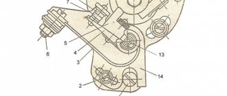
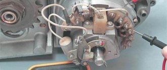
Rice. 11.3 – screws; 2 – eccentrics; 4 – breaker base; 5 – cam; 6 – rotor mounting bolt; 7 – stator fastening screw; 8 – terminal block; 9 – brush holder; 10 – capacitor.
BSZ on IZ Jupiter 2 6volt, part 1
Let's move on, it became boring to do nothing, on forums and social networks I read about the Contactless Ignition System.
I WILL SAY RIGHT AWAY: EVERYTHING WORKS ON 6 VOLTS
(new)
BOARD NETWORK
.
Many people have a question whether it will work on a 6 volt on-board network, because all the components in stores are for a 12 volt on-board network.
I took a break from the Internet, I found articles where YAVISTS installed this system on their motorcycles and it worked, information was provided there that almost all components start working from 5.5 (6.0) volts. I saw the same thing in the instructions for them.
Fuel level
Adjusting the K-65 carburetor begins with measuring the amount of gasoline in the tank of the float section. To do this, you will need to prepare a certain list of tools. Almost every home craftsman has them. The tool will be required during the process of dismantling the carburetor.
When the device is removed from the slots, you will need to remove the cover from it. It covers the float chamber. Next you need to take a ruler. The float has a special tongue. It needs to be unbent and bent to make adjustments. Due to this, the fuel level in the chamber will change.
You will need to place a ruler on the connector plane. Next, the tongue must be adjusted correctly. The strip on the float should be at 13 mm. The deviation is ±1.5 mm. The floats themselves must be level. The adjustment must be made very precisely. The operation of the carburetor depends on this.
Carburetor - removal and disassembly
It is possible to partially disassemble the carburetor (removing and washing the throttle, repairing the drive, etc.) without removing it from the engine.
1. Place the motorcycle on the center stand.
2. Remove the protective covers.
3. Shutting off the fuel supply, disconnect the fuel hose from the carburetor.
4. Use a screwdriver to loosen the clamp and disconnect the rubber air filter pipe from the carburetor.
5. 10 mm
Unscrew the mixture corrector nut.
6. Remove the corrector plunger assembly.
7. Disassemble the corrector plunger.
8. Pulling the cable sheath upward, unscrew the throttle valve cover.
9. Remove the throttle valve assembly. Cover the hole with a clean cloth.
10. To replace the cable, you need to compress the damper return spring, and, pushing the cable down, remove its end from the cut in the damper needle nut.
1. 12 mm
unscrew the two bolts securing the carburetor adapter pipe to the cylinder. We remove the carburetor with the pipe, being careful not to tear the paronite gasket.
2. Hold the bolts with a 12mm
, unscrew the nuts securing the adapter pipe
with a 13 mm
. We remove the pipe.
1. Using a screwdriver, unscrew the two screws securing the carburetor cover.
2. Remove the float chamber. There is a paper gasket underneath, be careful not to tear it.
3. Using a thin drift, carefully knock out the float axis.
4. Use thin pliers to remove the axle.
5. Remove the float along with the locking needle.
8 mm socket wrench
We turn out the seat of the shut-off valve.
7. Using a screwdriver, unscrew the jets of the main dosing system and the idle system.
8. 6 mm
turn out the additional jet.
9. 12 mm
We turn out the fuel-emulsion nozzle of the main dosing system.
10. Turn out the “quantity” and “quality” screws.
13. We wash all carburetor parts, except gaskets and rubber parts, in acetone or solvent for nitro paints. We clean all channels and jets with copper wire or toothpicks soaked in solvent, and blow them with compressed air from the compressor.
It is unacceptable to clean carburetor jets with steel wire, needles or any other tool.
We assemble the carburetor in the reverse order, while lubricating the rubber o-rings, threads and gaskets with engine oil or BSK brake fluid containing castor oil.
We tighten the “quantity” and “quality” screws until they stop. Then we unscrew the “quality” screw one turn (preset), and unscrew the “quantity” screw five to seven turns.
We check the operation of the shut-off valve. When the carburetor is oriented with the throttle channel down, the air supplied by the mouth into the inlet fitting should not pass through the valve.
Adjusting the position of the needle of the main dosing system is carried out by rearranging the lock washer in the grooves of the needle:
- washer to the left - enrichment of the mixture; - washer to the right - lean mixture.
Step-by-step guide to installing and adjusting the ignition
To carry out the setup, you need to prepare a special tool, a tester, and a light bulb with two wires.
A caliper will be needed as a depth gauge. To set the gap it is convenient to use a special feeler gauge. Setting up SZ on IZ Jupiter 5 consists of the following steps:
- First open the generator cover.
- To make it more convenient to work, remove the right cover from the crankcase.
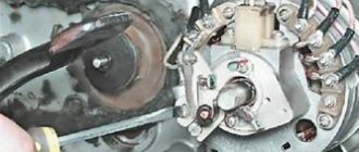
- Using the generator bolt, turn the crankshaft clockwise. It is necessary to ensure that the breaker contacts open to the maximum distance.
- Unscrew the screw a little and turn the eccentric. It is necessary to set a gap between the contacts equal to 0.4-0.6 mm. After this, tighten the screw well.
- Rotate the crankshaft in the direction of movement of the clock hand. The piston should be installed at TDC.
- You need to turn the crankshaft in the opposite direction, that is, counterclockwise. In this case, the piston should not reach TDC; a distance of approximately 3.0-3.5 mm should remain. By loosening the screws, you should establish the beginning of the contact closure. After this, the screws must be tightened tightly.
- To determine if the contacts are open, use a test light with wires. One wire must be connected to the breaker hammer terminal, and the other to ground. After turning on the ignition, when the contacts are closed, the light should light up.
- If BSZ is installed on IZ Jupiter, then there is no need to set the gap. To determine the moment you need to use a tester. The device should be set to measure voltage. The probes must be connected to the 2nd and 3rd contacts of the DC. While the modulator is not in the DC, the voltage reading on the tester should be 7 V. At the moment when the modulator is in the DC, the voltage reading should be in the range from 7 to 0 V. At this moment, a spark is formed.
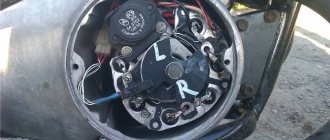
- The procedure must be performed on each cylinder. It is advisable to start adjusting the gap on the left breaker. When the left breaker is configured, you can move on to the right one.
Ignition adjustment, but let's start with a little introduction.
If now motorcycles from foreign manufacturers predominate on the roads, then literally 20-30 years ago only domestic Izh “Jupiter” and “Planet” rode on our roads. 2 years difference in production, identical appearance, there are not many differences in them, but still Jupiter-5 wins due to its two-cylinder engine and its easier starting.
Main components:
- Two-stroke, two-cylinder 347.6 engine;
- Air or liquid cooling system;
- Automatic clutch release mechanism;
- Drum brakes;
- 18 wheels;
- The steering wheel has a conventional instrument panel (speedometer, ignition lamp, etc.);
- Two shock absorbers. Setting up the ignition on Izh Jupiter 5 must be done in compliance with all rules. To do this, you need to know the exact algorithm of actions when carrying out this event. Therefore, in this article we will describe in detail how to set the ignition on Izh Jupiter-5.
Maintenance Features
Often during operation it is necessary to correctly set the gap between the contacts of the breaker. To do this, you need tools and a diagram to see which elements need to be dismantled.
The algorithm of actions is as follows:
In general, all the wiring of IZH Planet 5 is very easy to do with your own hands.
The need for such work often arises when operating a motorcycle:
Often the sound signal suffers during operation. Its malfunctions manifest themselves in the form of deterioration in sound quality.
To restore its functionality, you must perform the following procedure:
Conclusions: we are confident that this article will help you in servicing motorcycles of the IZH family (see also the article about). Both the attached diagrams and description will help you avoid making mistakes during operation.
While easily fixing mechanical failures, motorcyclists experience difficulties if the electrics fail. It’s completely in vain, the wiring diagram of the planet Izh 5 is not complicated, it’s easy to figure out.
There is no need to have special stands and equipment for repairs. A minimum knowledge of electrical engineering and a simple avometer (tester) is enough; even often you can get by with just a test lamp.
We will tell you in more detail about the main electrical wiring components and possible malfunctions. The Izh Planet wiring diagram makes it easy to find a broken wire or damaged insulation (for example, a bad contact always gets hot).
In this case, we look to see if there is a spark at the coil output and at the output at the spark plug contact. Let's take a closer look at the main wiring components of the Izh Planet.
Electrical circuit of the Voskhod motorcycle
Features of setting up a starline car alarm
Central switch. 2. speedometer. 3. Speedometer light. 4. Headlight. 5. Headlight lamp. 6. City driving lamp. 7. Sound signal. 8. Direction indicator lamp. 9. Direction indicators. 10. Direction indicator switch. 11. Electronic switch. (D - sensor terminal, K - ignition coil terminal, G - generator terminal.) 12. Throttle. 13. Relay breaker. 14. Generator. 15. License plate lamp. 16. Brake signal lamp. 17. Rear light. 18. Wire connection block. 19. Brake light switch. 20. Shielded spark plug cap. 21. Spark plug. 22. High voltage wire. 23. Ignition coil. 24. Light switch.
Wire colors: sn. - blue, cf. - gray, g. - blue, g. - yellow, h. - green, k. - red, kor. - brown, op. - orange, f. - violet, h. - black.
The generator is good, but it needs to be rewound to 12V, otherwise the wiring will have to be redone a lot and the battery will not be able to be made into the lighting circuit; all the lamps except the neutral lamp and the 12V control lamp are easier to find than original ones. The faceplate was made according to drawings by Dmitry67:
The generator flywheel was not mounted as in the article, but as it should be - on a key. Of course, the rotor is 3 millimeters deeper than it should be, but everything works as it should
Article - “Does the Planet Need a Battery?” - have already been posted. This is right. It all started with this article for the majority of current users of such modifications.
However, there were earlier versions. I'll post one more to complete the collection. From the book of Boris Fedorovich Demchenko »
There are some mistakes there.
I converted several IZh motorcycles to Voshodov ignition (IZH 56, IZH P 3, IZH P 5, IZH PS, IZH Yu 3, IZH Yu 5.)
In the process of this work, optimized drawings of adapters were developed. The preferred material is alloy D 16. It does not rust - it is easy to process and holds the thread normally. If there are no suitable aluminum alloys, plain steel will do. The only negative is that it can rust. I don’t recommend stainless steel - it’s difficult to process it later on site. Drilling is also vicious. I tried to make one adapter from hot stainless steel - I did it but cursed everything.
Briefly speaking. The installation of the IZH generator 6 volt and 12 volt is different. Accordingly, different adapters are needed, depending on the motor model.
Drawings of blanks for a turner:
During manufacturing, it is advisable to sharpen the adapter from one installation. That is, at the end of processing it should be like a ready-made adapter - attached with the narrow end to the blank. And then they cut it off from the blank and trim the cut edge. This will create a part without compromising the wall thickness.
A little later there will be a continuation. This is not all I wanted to write yet.
Dosage system
The K-65 carburetor is adjusted especially carefully in the area of the metering needle. Its position must be carefully adjusted. The engine must be well warmed up. If it has already cooled down, you need to ride the motorcycle for some time on the highway.
On a straight section of the route, you can evaluate the engine's performance. If turning the throttle does not have sufficient effect, you will need to raise the needle. This will lead to an increase in gasoline in the fuel mixture. If after the next trip carbon deposits appear on the spark plugs, you will need to lower the throttle needle one notch.
This approach will ensure stable operation of the engine at medium speeds. This is the most frequently used mode when operating motorcycles. The maximum speed allows you to adjust the measurement of the jet cross-section. When the throttle is turned all the way, it will ensure the operation of the system.
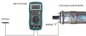
Determining why the ignition coil heats up
The main function of the coil is to convert low voltage voltage, which comes from a generator or battery, into high voltage. There is a generation of high-voltage electrical pulses on the candles. The ignition coil connection diagram provides a certain operating mechanism: when the starter is turned on, thanks to the contact disk, an additional resistance is turned on, this leads to an increase in the current passing through the primary winding, and, as a result, the voltage of the secondary winding increases, which contributes to the reliable ignition of the working mixture.
Malfunctions of the ignition coil can be noticed by the following symptoms. First of all, if it has a high temperature when the engine is off. The cause of this symptom may be turning the key to the active position for a fairly long period with the engine turned off. The next alarming sign is a short circuit, when the engine does not start at all, resulting in a smell of burnt insulation and strong heating of the lock, as well as the starter. In this case, repair and replacement of the ignition coil is necessary.
Unstable operation of the car also helps to understand that diagnostics are urgently needed. It begins to twitch when driving at speeds exceeding 60 km/h, and during a long stop, for example in a traffic jam, the spark may disappear altogether, then the ignition coil should be checked as soon as possible.
Required Parts
In order for the ignition system to work correctly, a number of auxiliary parts are required. They are listed below:
Modulator
The most difficult stage is the production of the modulator
It is important to maintain the required shape. The more reliably the required dimensions are observed, the lower the likelihood of problems occurring after implementing the system, that is, there will be no need to adjust it using a file
The ignition timing must match on any cylinder used.
The bolt hole must be located in the middle. Otherwise, the engine operation will not be synchronized. It is also recommended to check the integrity of the crankshaft bearings. If you find defects, you should immediately replace it.
The contact ignition is not able to work normally if the bearings are damaged. The thickness of the part should not exceed one and a half millimeters. If it is thin, it will not be possible to avoid deformation, and if it is thick, it will come into contact with the surface of the hall sensor housing.
To create the plate, it is allowed to use any material except steel. Aluminum and others should not be used as they are not magnetic. The drawing that must be followed can be found in the public domain. The presented diagram will be useful to those people who decide to modernize the vehicle ignition device. Below are methods for installing electrical ignition devices in Jupiter.
It must be turned by a professional turner. He will make a simple disk and draw on it the markings of elementary distances between the corners. Then, in accordance with it, you will cut out the necessary sectors at home. The cost of the modulator is seventy rubles.
It is not advisable to use an ordinary plate, since its width is less than twelve millimeters. This will not be enough to fully accumulate the energy resource in the coil. Of course, it can be installed, but achieving four thousand revolutions per minute will become impossible.
In addition to the above you will need:
Adjusting the K-68 carburetor on the IZH Planet-5 motorcycle
The K-68I carburetor was installed on the Izh Planet-5 motorcycle more often than others. With proper setup and proper care, the motorcycle starts quickly, runs smoothly and without complaints.
To adjust the K-68I carburetor you will need a flat-head screwdriver, pliers, and a ruler. For clarity and ease of adjustment, use the K-68 carburetor diagram.
Algorithm for adjusting the Izh Planeta-5 carburetor:
Knowledge 124 stunned
Do you want to sell swedes? Be aware, yak
Cdi ignition IZ Jupiter
Motorcycle parts and accessories » Motorcycle parts
Guaranteed to withdraw the goods, or the money back to the card. More details.
900 UAH
Spark plug Priority APS VAZ GAZ AZLK IZH UAZ
Auto parts and accessories » Auto parts
40 UAH
Kharkiv, Kominternivsky Yesterday 16:13
Ignition switch Moskich 412 IZH new
Auto parts and accessories » Auto parts
80 UAH
Vinnytsia, Zamostyansky Yesterday 14:01
ignition coil for IZH 6V
Motorcycle parts and accessories » Motorcycle parts
Guaranteed to withdraw the goods, or the money back to the card. More details.
100 UAH
BSZ contactless ignition Izh Jupiter spare parts analysis planet has everything
Auto parts and accessories » Auto parts
800 UAH
Selling ignition for motorcycle Minsk, Voskhod, IZH
Motorcycle parts and accessories » Motorcycle parts
Guaranteed to withdraw the goods, or the money back to the card. More details.
700 UAH
BSZ Java IZH MT electronic ignition contactless system. Set.
Motorcycle parts and accessories » Motorcycle parts
Guaranteed to withdraw the goods, or the money back to the card. More details.
440 UAH
Ignition coil 6 volt Izh Java Minsk
Motorcycle parts and accessories » Motorcycle parts
50 UAH
6 volt ignition coils for Izh motorcycle
Motorcycle parts and accessories » Motorcycle parts
Guaranteed to withdraw the goods, or the money back to the card. More details.
150 UAH
Ignition coil IZH
Motorcycle parts and accessories » Motorcycle parts
100 UAH
Ignition of IZ Jupiter.
Motorcycle parts and accessories » Motorcycle parts
Guaranteed to withdraw the goods, or the money back to the card. More details.
Technical specifications
Multi-disc clutch, in an oil bath with an automatic release mechanism. The gearbox is four-speed, two-way. Motor transmission is a rollerless double-row chain, gear ratio - 2.57. Transmission from the gearbox to the rear wheel is a roller chain, gear ratio - 2.33. The frame is tubular and welded. The front fork is a telescopic spring type with hydraulic shock absorbers. Rear suspension pendulum spring with hydraulic shock absorbers Type of brakes drum Type of wheels easily removable, with tangential straight spokes. Tire size 3.25-19″
Electronic ignition for the IZH PLANET 5 motorcycle
Generator Izh Planet 5 on permanent magnets, with a contact ignition system that operates independently of the battery, with automatically adjustable ignition timing. Therefore, on Izh Planet 5, electronic ignition can be installed from a VAZ 2108. Installation takes about two evenings. In a nutshell:
1. Manufacturing and installation of a corner
(Fig. 1) for attaching the Hall sensor (the standard contact ignition was not touched!) into the standard threaded holes on the generator platform (photo. 2). Both elements are made of ordinary iron with a thickness of 1.5 mm.
3. Installing the reel under the tank
(photo 3). There is not enough space, but it can be installed. I had to cut out the fastening sleeve.
4. Mounting the Switch
(photo 4). I turned and turned for a long time, and found a place only near the signal, under the tank.
5. Wiring
(photo. 5). Nothing complicated, except for pulling the casing with wires from the Hall sensor under the clutch cover.
6. Connecting all the elements
according to the diagram (Fig. 6).
Set the ignition timing to 3.5 mm before TDC. It is worth considering that the sensor produces a pulse when the modulator exits the gap. Start the engine. If everything went well, then you can safely drive, having a contact ignition system as a backup. Everything went smoothly for me. The start was easy and there were no problems. When the engine was warm, the speed was stable, and the engine responded perfectly to the accelerator handle.
Ignition timing former (FUOZ)
I ask the skeptics to calm down, FUOZ is working and, in all likelihood, will be put into production. There will be one manufacturing option for 1 and 2 cylinder engines. A new feature has been added - individual settings for a specific engine. Those. the characteristic will be set by the driver himself, right on the go. Moreover, the established characteristic will be remembered and used in the future. The algorithm is simple: 1) start the engine; 2) let it reach operating temperature; 3) start moving; 4) having fixed the throttle handle in a certain position, adjust the OZ using the FUOZ potentiometer; 5) press the “remember” button 6) repeat step 4. for other speeds. Because such templates may be a lot, then for a loaded motorcycle you can build another characteristic and switch to it via the menu item. It is possible to switch between m/s templates when the specified temperature is reached, which will also be very useful. This way you will get an almost ideal performance for your engine.
FUOZ is a device for forming the required ignition timing of a motorcycle (and not only a motorcycle) with extended service functions. The device is surface mounted and fits under the LCD (PC1601LRS-FNH-B/PC1601F D). FUOZ is connected to the gap of the Hall sensor (control output of the DC) and 6 con. switch. The OZ schedule is shown in the figure. The graph is taken from a similar device, which is made on an ATMEL microcontroller and runs 100% on IZ Jupiter 5.
If desired, set the characteristic for a specific engine independently, according to the algorithm above. The choice of characteristic is displayed on the LCD. The ideal option, of course, is a knock sensor + throttle position sensor + air flow sensor + temperature sensor + injector
The device can be made without an LCD, for simplicity. In this case, the visibility of the device’s operation is lost, and it is more difficult to adjust some parameters.
The initial SOP is set to about 30 degrees (7 mm before TDC). FUOZ ensures the production of the required delay with high accuracy. At minimum speeds, the pulse delay will be maximum (SOP is 0 degrees), and at high speeds, vice versa (SOP tends to 30 degrees).
The FUOZ diagram for the option with LCD is shown in Fig. 9. The FUOZ is made on a PIC controller MicroChip PIC16F873, operating at a frequency of 4 MHz. The circuit is simple and does not require any explanation; the parts are surface-mounted (except for the LCD).
Here are drawings of a (test!) double-sided surface mount printed circuit board measuring 84x57mm.
All this fits into the dashboard of a motorcycle.
The main menu item displays: engine speed, SOP, on-board network voltage Temperature, octane correction angle Multi-spark mode (Options: On/Off). If “On”, then at revolutions less than 400 it produces three sparks. Indication of overtemperature (Options: Off/100/120/140/160) Indication of overspeed (Options: Off/4000/5000/6000) Backlight (Options: On/Off ) UOZ mode (Options: Pattern #1 / Pattern #2 / Pattern #3) Switching between patterns when the set temperature is exceeded
Setting the appropriate options
Setting up the BSZ on Izh Jupiter 5 also requires special attention. The ignition is turned on with the tachometer connected. After thirty seconds, indicators of 3000, 4000, 5000 rpm should appear on the device panel. If they are present, then the switch is working correctly.
In other cases, you should pay attention to previously grounded candles. We insert a screwdriver into the hall connector, and then pull it out
A spark should appear on the spark plugs. If it was not possible to cause a spark using the steps described above, then the reason for the incorrect operation is incorrect connections.
The setup looks like this. The dial indicator is unscrewed and the cylinder piston is adjusted. Having connected the voltmeter to the second and third connectors, you need to start rotating the modulator axis. After a jump from 7 to 0.1 volts is detected, the modulator must be secured with a nut. Usually the required advance angle is set.
The test run should be successful if you install the components yourself according to the instructions. Now you can use BSZ.
The main problem with the Izh Jupiter motorcycle engine is the standard contact ignition system. Any owner of Jupiter sooner or later faces the problem of failure of one of the cylinders due to a change in the gap in the contacts or failure of the capacitor. Adjustment helps, but usually not for long. This problem can be radically solved by installing a contactless ignition system on a motorcycle.
Single-channel BSZ.
There are probably many options for BSZ design, but we won’t consider them all. Let's focus on the simplest, and probably the most common option in our country. There is no motorcycle market or motorcycle store nearby where you can buy a factory-made BSZ, and there is no turner with a machine nearby either. We will proceed from this.
Minimum set for installation
But we can’t do without a minimum set, so before you start work, you need to stock up on the following components, which are sold in any auto shop or car market in our country:
1. Switch from VAZ 2108
2. Hall sensor from VAZ 2108
3. Set of wires for BSZ from VAZ 2107 (from distributor (Hall sensor) to switch)
4. Two-terminal ignition coil (from an Oka or Gazelle car with a ZMZ 406 engine)
5. Two automotive silicone high-voltage wires of the required length with caps for spark plugs (you can buy a kit for a VAZ and take it from there, you can simply find used wires, after first making sure they are working)
Next, in addition to the components, we will need a small flat piece of sheet steel 1-1.2 mm thick to make a modulator and a plate for the Hall sensor. I warn you right away that stainless steel or non-ferrous metals are not suitable for the manufacture of the modulator, since they are not magnetic materials. To make a plate for the Hall sensor, you can use any material of sufficient strength.
Tools you may need are a drill with drills, files, a chisel, a hammer and other tools that, as a rule, are found in any garage.
Rework process
We dismantle the old ignition system. We remove the plate with contacts, capacitors, ignition coils with high-voltage wires from the motorcycle. We install the switch in the right glove compartment.
We attach the ignition coil to the frame under the tank. We connect the wiring connector to the switch, connect the black ground wire from the connector to ground. We connect the wire from terminal No. 1 of the switch connector to one of the coil terminals. We connect the second terminal of the coil to the old wiring, to the wire to which “+12V” is supplied when the ignition is turned on. In the old wiring, this wire connected both ignition coils. From it we pull an additional “+12V” wire to the switch, which we connect to the 4th wire in the connector. We carefully isolate everything. We insert the wire with the connector to the Hall sensor into the cavity of the generator.
You can check the functionality of the system. We connect the Hall sensor to its connector, connect the high-voltage wires to the coil and to the spark plugs. We provide reliable weight to the candles. Turn on the ignition and pass a metal object (you can use a flat screwdriver) through the Hall sensor slot. The spark plugs should spark. The scheme is working. (If there is no spark, then something is connected incorrectly and everything needs to be checked again.) Now it remains to supply a spark at the right time to the cylinders, for this:
Main stage
As noted in the assembly diagram of the Izh-Planet 5 box, further disassembly operations are carried out above the insides of the roof of the unit, since the secondary shaft and sector could remain in it. If it is necessary to remove them, you need to straighten the petals of the lock washer, unscrew the nut, remove the star and washer. Holding the gear very carefully to prevent the shaft from jumping out, the cover is moved to a clean and flat surface with the gear facing up.
It is worth noting that the bearing of this part of the assembly does not have a retaining ring. Therefore, when removing the shaft with bearing, the rollers may fall out, so be careful. If the specified element has exhausted a decent service life, there is a risk that when dismantling the secondary shaft, the outer ring may jump out of the seat and remain on the rollers. Next you need to start pressing out the oil seal. To do this, the installation rings are removed from the hole in the cover, after which the outer ring of the bearing is removed.
Differences from the second Planet
For many modern citizens, the information that domestic motorcycle manufacturers worked tirelessly to improve their models in an era of total shortages may come as a surprise.
Note! The fact takes place, moreover, it is supported by official documents, in particular 1970N04P16-17 - this is the outgoing number of the factory newsletter, which described the changes made.
In the photo - official materials of the Izhmash Design Bureau
In what cases is ignition adjustment necessary?
During the operation of the vehicle, the owner faces many problems. The most serious failure is related to the engine. In order to spend significant funds on major repairs, it is necessary to monitor the technical condition of the motorcycle and carry out preventive work, including adjusting the valves and valves (video author - Hana Rulyu).
If you do not monitor the SZ, then the motorcycle engine may not reveal its full potential and will not work at full capacity. This can lead to a reduction in its service life. An ignition adjustment is necessary if the engine is running poorly, the muffler or carburetor is firing. True, before setting up the SZ, you should make sure that the cause of the malfunction is in it.
It happens that the flywheel bolt, which connects the two halves of the crankshaft, comes loose, begins to play and does not work well. Sometimes he even cuts the key.
Setting up the SZ may be necessary after repairing lock 5. The installation and connection itself are carried out according to the diagram.
SZ diagram of the IZh motorcycle
FORGET ABOUT THE BATTERY
Motorcycles of the Izh and Java brands can be quite easily converted to batteryless ignition. I did this seven years ago and still have no complaints. What is necessary? If the motorcycle has 6 V electrical equipment, then the 7 V generator set is from Minsk or the old Voskhod (with contact or electronic ignition); if at 12 V, then at 14 V - from the new “Voskhod”. Moreover, generator rotors can be either with removable or non-removable cams (in the first case, the installation procedure is simpler). For 2-cylinder engines (with electronic ignition), an additional sensor coil and another electronic switch will be required. Finally, the adapter flanges are turned from steel on a lathe and filed by hand, with a configuration depending on the brand of motorcycle.
General recommendations
The carburetor must be in good working order. If there is any abnormality in its system operation, it is necessary to carry out system maintenance.
If necessary, the system will need to be thoroughly cleaned. All consumables are replaced with new seals. The air filter must be clean. If necessary, it must be washed. In some cases it will need to be completely replaced.
When adjusting the carburetor, the engine must be warm. To do this, you can drive several kilometers along the highway. Only after this can you begin the procedure described below.
Ignition adjustment
First you need to determine which contact is used for which cylinder. Set the contact gaps to 0.4 millimeters; if the cam is very worn, reduce the gap to 0.3 millimeters. Next, unscrew the spark plugs and set the piston in one cylinder to top dead center. Insert any clean stick instead of a candle and make a mark. Measure 3 millimeters from this mark and align the piston to the new mark. Using a screwdriver, loosen the contact plate of this cylinder. Insert tissue paper between the contacts and turn the plate counter-clockwise until the paper can be pulled out. Instead of paper, you can connect a light bulb, one wire to ground, the second to contact. Rotate the plate until the light comes on. The second cylinder is adjusted in the same way as the first.
After all the procedures, all that remains is to add oil and gasoline, the motorcycle is ready for use. Correct wiring is the key to long and flawless operation of the Izh Jupiter 3.