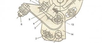
Installing the ignition of IZh motorcycles involves adjusting the maximum distance of the switch contacts. And the second most important moment is the spark. On single-cylinder IZh motorcycles with a G-36 M 1 generator, the gap is set by turning eccentric 1 to the right or left, with screw 2 loosened. Before installation, turn the crankshaft and stop for a moment at the maximum contact divergence. In this position, adjust the gap. We set the maximum distance between the contacts to 0.35 mm - 0.45 mm.
It is recommended to set the ignition timing by removing the cylinder head. The piston must be within the dead center distance specified in the manufacturer's instructions. For example, for Planet 3 - (3.5-4.0 mm), Planet 4 - (3.0-3.5 mm), Planet Sport - (3.5-3.8 mm). In this position of the piston a spark should form. Adjustable by turning the entire jackhammer with the 10 bolts loosened.
On IZH-Yu motorcycles, the gaps between the switch contacts are adjusted in the following order: by turning the crankshaft with a pedal start, set one of the switches to the position of completely opening the contacts and, by loosening screw 4 using eccentric 3, set the gap, which should be 0.4-0 .6 mm. Then the gap is set in the same way on the second pair of contacts.
The ignition installation of IZh motorcycles is carried out with the spark plugs turned off. Inserting the dipstick into the hole under the spark plug in the right cylinder and turning the crankshaft using the kick starter, find top dead center and in this position make two marks on the dipstick: one at the level of the hole, and the second 2-3 mm higher. Then crank the crankshaft again using the kickstarter until the top danger reaches the point where the first m t mark was made. In this position, the contacts of the switch installed on the lower base should begin to open. Adjustment of the opening of the contacts is achieved by turning the base with loosened screws 2 and 7, which, having found the opening moment, are tightened. The tensile strength is determined using a light bulb connected to the switch terminal and ground.
After establishing the ignition timing in the right cylinder, proceed with the same operation and in the same sequence in the left one, turning the upper base of the switch with loosened screws 1 and 7.
Ignition Izh Planetka 5: options and adjustment functions
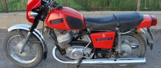
Probably, motorcyclists, despite the enormous selection of modern cars offered by foreign companies, trust Russian brands more. One of the favorite models of two-wheeled vehicles among Russian buyers to this day remains the IZH bike, which was produced at the Izhevsk Automobile Plant from 1987 to 2008.
The Izh Planetka 5 bicycle, which was created during the years of perestroika, was primarily intended for use on hard road surfaces. The model was equipped with an electric motor starting system. Therefore, for a long time, bicycles were needed especially by middle-income people. At the same time, some motorcycles were produced with outdated contact switches, which is why the owners of such “bicycles” probably often encounter inaccuracies in the ignition option for the Izh Planetka 5 bicycle.
How to correctly configure the ignition of Izh Planetka 5
It is best to make and adjust the ignition of an Izh Planetka using a special tool, which was once included in the factory kit of each individual model. If you don't have such a tool, use a regular caliper.
See:
What you need to set up the launch system on Izh Planetka 5, you will need the following tools:
- a probe, that is, a 12-volt light bulb with 2 wires;
- depth gauge (vernier caliper);
- special probes for precise measurement of gaps.
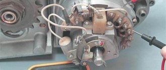
To correctly install the Izh Planet ignition, you must first remove the cover from the generator. If necessary, for convenience, you can unscrew the right crankcase cover.
In addition, to adjust the ignition of Planet 5, you should perform the following steps in turn:
- rotate the crankshaft clockwise, since proper torque setting will be performed when the switch is opened strongly;
- loosen the bolt slightly by immediately turning the eccentric;
- enter the required gaps (0.4, 0.6 mm);
- re-tighten the bolt;
- turning the crankshaft clockwise again, set the piston to the TDC mark;
- turning the crankshaft in the opposite direction, bring the piston 3. 3.5 mm to the TDC mark;
- loosen the bolts;
- set the start of opening contacts;
- retighten the bolts and turn the Planet 5 ignition on.
Installation process
It won’t take much time to replace the ignition, maybe a day. The necessary parts can be removed from the Oka vehicle. Electronic ignition is a set of wires, a generator, a two-terminal ignition coil, a Hall sensor and a switch.
There is no need to make any changes directly to the generator itself. You just need to remove the cams and, where there is space, attach a Hall sensor. It is very important that the modulator plate passes through the slots of the sensor itself. Thanks to the modulator plate, smooth ignition operation is ensured.
Unstable sparking is often caused by an incorrect design of the so-called magnetic flux contactor. In this case, you need to carefully study its placement in relation to the sensor. Overlapping of the magnetic circuit or magnet is unacceptable in the open state of the contactor, while the closed state of the contactor implies complete overlap of these two elements. If this is not the case, then most likely the sensor will emit weak signals to the switch. As a result, unstable engine operation will be observed.
To make a modulator you will need a steel disk with a cutout of 0.8-1 mm. It is important to maintain a ratio of closed to open periods of 2:1. The angle of the cutout in the modulator depends on the type of main power unit. If the main power unit is 1-cylinder, then the angle is 120 degrees. On 2-cylinder engines, an angle of 60 degrees is maintained. The width of the cutout starts from 11 mm and more, but not less. You should also know: a spark occurs when the modulator “opens” the sensor. This is very important when setting the ignition timing.
Before installing electronic ignition on the IZH Jupiter 5 motorcycle, check that there are no large plays on the generator shaft. If they are, you should replace the generator bearings in order to get rid of the “bumpiness”.
How to set the ignition on Izh Planeteka 5 without a micrometer
Ignition configuration on the IZH Planetka 3, 4 and 5 model.
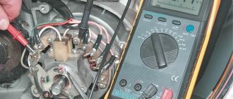
To find out when the opening begins, use a light bulb. To do this, you need to connect the light bulb with wires from the textbook to ground, and connect the other wire to the terminal. Then you need to turn on the ignition of Planet 5. The engine should start when the contacts open - this will be indicated by a burning light.
See:
Having slightly unscrewed the bolts to install the ignition on the Planet, you need to turn them all the way (and clockwise). The light bulb will not shine here. Then slowly turn the contacts again, in the opposite direction, until the light comes on again. At this moment a spark should appear. So, of course, regulate the ignition of the Izh Planetka.
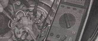
If your bike is equipped with a contactless engine starting system, then there is no need to set distances, since the moment of spark formation is determined using a special tester. In such conditions, to install the ignition on Izh Planetka 5 you must:
- correctly install the device for measuring voltage (up to 20 volts);
- connect the device to the 2nd and 3rd pins of the Hall sensor.
Motorcycle Features
According to industry norm, the motorcycle had an alphanumeric index:
- IZH 7.107-010 – basic model;
- IZH 7.107-020 was already equipped with a new lubrication system and improved front axle suspension. In addition, the wiring diagram of the IZH Planet 5 motorcycle had a contactless ignition system, independent of the battery;
- IZH 7.107-030 was equipped with a spring-hydraulic shock absorber and a redesigned rear wheel brake drive;
- IZH 7.107-040 was produced with modified kinematics and a modified front wheel brake. The wiring diagram on IZH Planet 5 remained contactless until 2008.
In addition, a side trailer (sidecar) or a universal cargo platform (without a seat) could be attached to the motorcycle.
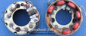
Generator
The motorcycle is equipped with a 3-phase alternator, which has an electromagnetic excitation circuit. The principle of its operation is based on some features. So, the electrical circuit of “IZH Planet-4” looks like this: the current is supplied to the rectifier, which, in turn, converts it into direct current, then supplies it to consumers. The factory instructions for the generator contain the following elements:
Voltage regulator with rectifier “BPV-14-10”;
The head light circuit consists of the rear brake light, parking light and color control light. The motorcycle is equipped with a speedometer with mileage indicators (daily and total), a tachometer, indicator lamps for turn signals and head lights, a voltmeter and an engine temperature sensor. Very often during operation it is necessary to adjust the gap between the contacts of the breaker. To do this, it is best to use a diagram and special tools to know which elements need to be dismantled.
The wiring diagram of IZH Planet 5 is not complicated, and it is quite possible for a person, even with little experience, to independently check its serviceability and carry out repairs. It is enough to know the principle of operation and its main problems, which owners of the IZH P5 motorcycle often encounter.
Ignition on Izh Planet 3
Post by Isaak » 09 Mar 2011, 00:14
Re: Ignition on IZH Planet 3
Post by 5motor5 » Mar 09, 2011, 11:59 am
Re: Ignition on IZH Planet 3
Post by 5motor5 » Mar 09, 2011, 12:01 pm
Re: Ignition on IZH Planet 3
Post by Isaak » 09 Mar 2011, 13:53
Re: Ignition on IZH Planet 3
Post by 5motor5 » Mar 09, 2011, 8:10 pm
Rotating the crankshaft clockwise, find the maximum gap between the cams, then make sure that it is 0.35 mm, adjust if necessary. then place the piston at TDC, and by rotating the crankshaft counterclockwise, lower the pistons 3.5 mm down. Then, by rotating the base of the cams, find the initial opening of the contacts.
The light bulb must be powered from a separate power source, and it should light when the contacts are closed, and should go out when opened.
The initial opening of the cams can be determined more simply - put a piece of paper between the contacts; when the contacts open slightly, it will stick out freely
The cams should not open for a moment, they should be open for quite a long time, otherwise the spark will be weak
Re: Ignition on IZH Planet 3
Post by 5motor5 » 09 Mar 2011, 20:20
Re: Ignition on IZH Planet 3
Post by svetovor200961 » Mar 21, 2011, 12:44 pm
Re: Ignition on IZH Planet 3
Post by Maver-Dime » Mar 21, 2011, 4:35 pm
Re: Ignition on IZH Planet 3
Post by Detonator » March 21, 2011, 5:07 pm
Re: Ignition on IZH Planet 3
Post by V-aga » March 21, 2011, 05:54 pm
Isaak, the electrical equipment of your motorcycle resembles a tricycle with one original wheel, one from a tram and one from a car
I’ll just tell you about the ignition with this generator: For its operation you need one wire - it goes from the breaker to the coil, the other end of the coil connects to ground. The light bulb in your case will not help you, it will never light up, for no reason. Even though the generator is easy to adjust It’s quite annoying and it looks like you don’t need it completely 1 You set the gap according to the maximum divergence of the breaker 2 The most annoying and important part is to set the outline. What kind of fruit is it? Without being too subtle, I will say that in order for there to be a normal spark, the breaker must open at the top of the sine wave. The technology is simple but tedious: you remove the spark plug cap, place the chazor from the wire on the body and begin to turn the base of the breaker back and forth relative to the generator until you find the position in which the spark power is maximum (the maximum gap is broken through) - do it better together - one kicks the kick, the second looks for this beast that outline When this position is found, the breaker is tightened and left for the next few years, usually until the breaker is replaced. 3 The ignition timing is set by turning the generator itself in the crankcase, a spark jumps at the moment the breaker breaks, but when adjusting there will be no spark and therefore the breaking moment will have to be controlled by eye, old people used to insert tissue paper into the breaker and catch the moment when it was released, if you need to be very precise then you can remove the wire of the coil and winding from the breaker during adjustment and catch the moment with a hook with a beeper or a light bulb with a battery.
Technical specifications
Multi-disc clutch, in an oil bath with an automatic release mechanism. The gearbox is four-speed, two-way. Motor transmission is a rollerless double-row chain, gear ratio - 2.57. Transmission from the gearbox to the rear wheel is a roller chain, gear ratio - 2.33. The frame is tubular and welded. The front fork is a telescopic spring type with hydraulic shock absorbers. Rear suspension pendulum spring with hydraulic shock absorbers Type of brakes drum Type of wheels easily removable, with tangential straight spokes. Tire size 3.25-19″
Help for owners of IZH Planet 4
The motorcycle left a good memory of itself among lovers of two-wheeled vehicles. Many of them willingly share tips on restoring and remaking their “iron horses.”
Electrical wiring diagram redrawn by motorcycle “fans” (from the black and white factory one)
Communication on the following topics is especially relevant:
- Modernization of the ignition system;
- Installation of alloy wheel rims;
- Modernization of the instrument panel;
- Troubleshooting electrical systems;
- Installing an alarm system on a motorcycle and altering the wiring;
- Converting the motorcycle electrical circuit to work without a battery;
- Interchangeability of electrical components and compatibility with other brands of motorcycles, for example, with Ural motorcycle wiring diagrams.
Switch Voskhod - electronic KET-1
The electronic switch KET-1 is designed to work in the ignition system complete with the G-427 generator and the B-300B high-voltage transformer. Allows you to obtain a secondary voltage of up to 18 kV, at a generator rotor speed of 250 to 7500 rpm. The switch is installed in the right toolbox. The base of the commutator is connected to the ground of the motorcycle. If the switch fails, it can be disassembled and repaired
The electronic switch has three output terminals with letter markings on the body >, > and >. The ground terminal is the base of the switch.
Maintaining the switch during operation comes down mainly to tightening the threaded connections, while avoiding stripping the threads. It is necessary to protect the switch from moisture getting inside it and onto the terminals from sudden shocks and exposure to high temperatures. You should also systematically check the reliability of the electrical connection of the switch base with >, because If this condition is violated, sparking on the spark plug stops.
Wiring Problems
Practice shows that if the motorcycle was stored in a dry garage and was not subjected to dubious alterations, then the Jupiter 5 wiring diagram lasts a very long time. From time to time you need to change some consumables, such as lamps and ignition coils, but otherwise it functions quite stably. However, this is not always the case and problems do occur, for example:
The problems described above can arise both due to natural wear and tear of wiring elements, and after incompetent intervention in the circuit. There is no universal solution to the problem in this case, and in order to find out what caused the breakdown, you should be patient and have some basic knowledge of the technical part of the motorcycle. First of all, you should get a multimeter or assemble a primitive network indicator using a 12-volt light bulb to “ring” the wiring for breaks. Having found a circuit node that is not working correctly or a wiring break, it will need to be eliminated, the network’s functionality re-checked, and so on, until operation is completely restored.
Required Parts
In order for the ignition system to work correctly, a number of auxiliary parts are required. They are listed below:
- Switch for BSZ VAZ cars. You should not choose exclusively from the low price segment. The Astro switch has a lot of positive reviews;
- Hall Sensor. The best option for Jupiter 5 is a similar manufacturer VAZ. By purchasing it in branded packaging, you protect yourself from counterfeits;
- Ignition coil with two terminals. You should choose between the gazelle engine number 406 or Oka with an electronic ignition system;
- A pair of silicone armor wires with rubber caps;
- The modulator is a butterfly-shaped plate made of iron.
Modulator
The most difficult stage is the production of the modulator
It is important to maintain the required shape. The more reliably the required dimensions are observed, the lower the likelihood of problems occurring after implementing the system, that is, there will be no need to adjust it using a file
The ignition timing must match on any cylinder used.
The bolt hole must be located in the middle. Otherwise, the engine operation will not be synchronized. It is also recommended to check the integrity of the crankshaft bearings. If you find defects, you should immediately replace it.
The contact ignition is not able to work normally if the bearings are damaged. The thickness of the part should not exceed one and a half millimeters. If it is thin, it will not be possible to avoid deformation, and if it is thick, it will come into contact with the surface of the hall sensor housing.
To create the plate, it is allowed to use any material except steel. Aluminum and others should not be used as they are not magnetic. The drawing that must be followed can be found in the public domain. The presented diagram will be useful to those people who decide to modernize the vehicle ignition device. Below are methods for installing electrical ignition devices in Jupiter.
It must be turned by a professional turner. He will make a simple disk and draw on it the markings of elementary distances between the corners. Then, in accordance with it, you will cut out the necessary sectors at home. The cost of the modulator is seventy rubles.
It is not advisable to use an ordinary plate, since its width is less than twelve millimeters. This will not be enough to fully accumulate the energy resource in the coil. Of course, it can be installed, but achieving four thousand revolutions per minute will become impossible.
In addition to the above you will need:
- A stud with an applied thread of seven millimeters, pitch 1, as well as a pair of nuts with washers of the corresponding parameters. The priority material for these components is brass. This is explained by the least magnetization of the plate from the generator rotor. If you use a standard bolt, then difficulties may arise with the introduction of ignition. The bolt tends to follow the modulator as it is tightened. However, it is necessary to observe the leading indicator, maintain the same position of the rotor and modulator, and tighten the bolt. It is advisable to use a pin, since many are not able to perform all the necessary actions in total;
- A set of wires with connectors for ignition without contact from VAZ. This part can be purchased or made with your own hands.
Carburetor - removal and disassembly
It is possible to partially disassemble the carburetor (removing and washing the throttle, repairing the drive, etc.) without removing it from the engine.
1. Place the motorcycle on the center stand.
2. Remove the protective covers.
3. Shutting off the fuel supply, disconnect the fuel hose from the carburetor.
4. Use a screwdriver to loosen the clamp and disconnect the rubber air filter pipe from the carburetor.
5. 10 mm
Unscrew the mixture corrector nut.
6. Remove the corrector plunger assembly.
7. Disassemble the corrector plunger.
8. Pulling the cable sheath upward, unscrew the throttle valve cover.
9. Remove the throttle valve assembly. Cover the hole with a clean cloth.
10. To replace the cable, you need to compress the damper return spring, and, pushing the cable down, remove its end from the cut in the damper needle nut.
1. 12 mm
unscrew the two bolts securing the carburetor adapter pipe to the cylinder. We remove the carburetor with the pipe, being careful not to tear the paronite gasket.
2. Hold the bolts with a 12mm
, unscrew the nuts securing the adapter pipe
with a 13 mm
. We remove the pipe.
1. Using a screwdriver, unscrew the two screws securing the carburetor cover.
2. Remove the float chamber. There is a paper gasket underneath, be careful not to tear it.
3. Using a thin drift, carefully knock out the float axis.
4. Use thin pliers to remove the axle.
5. Remove the float along with the locking needle.
8 mm socket wrench
We turn out the seat of the shut-off valve.
7. Using a screwdriver, unscrew the jets of the main dosing system and the idle system.
8. 6 mm
turn out the additional jet.
9. 12 mm
We turn out the fuel-emulsion nozzle of the main dosing system.
10. Turn out the “quantity” and “quality” screws.
13. We wash all carburetor parts, except gaskets and rubber parts, in acetone or solvent for nitro paints. We clean all channels and jets with copper wire or toothpicks soaked in solvent, and blow them with compressed air from the compressor.
It is unacceptable to clean carburetor jets with steel wire, needles or any other tool.
We assemble the carburetor in the reverse order, while lubricating the rubber o-rings, threads and gaskets with engine oil or BSK brake fluid containing castor oil.
We tighten the “quantity” and “quality” screws until they stop. Then we unscrew the “quality” screw one turn (preset), and unscrew the “quantity” screw five to seven turns.
We check the operation of the shut-off valve. When the carburetor is oriented with the throttle channel down, the air supplied by the mouth into the inlet fitting should not pass through the valve.
Adjusting the position of the needle of the main dosing system is carried out by rearranging the lock washer in the grooves of the needle:
- washer to the left - enrichment of the mixture; - washer to the right - lean mixture.
Dosage system
The K-65 carburetor is adjusted especially carefully in the area of the metering needle. Its position must be carefully adjusted. The engine must be well warmed up. If it has already cooled down, you need to ride the motorcycle for some time on the highway.
On a straight section of the route, you can evaluate the engine's performance. If turning the throttle does not have sufficient effect, you will need to raise the needle. This will lead to an increase in gasoline in the fuel mixture. If after the next trip carbon deposits appear on the spark plugs, you will need to lower the throttle needle one notch.
This approach will ensure stable operation of the engine at medium speeds. This is the most frequently used mode when operating motorcycles. The maximum speed allows you to adjust the measurement of the jet cross-section. When the throttle is turned all the way, it will ensure the operation of the system.