Generator Voskhod G-427
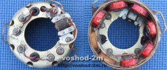
Generator G-427 alternating current with excitation from a permanent magnet with an inductive sensor of the electronic ignition system. In the grooves of the stator, made of stamped electrical steel plates, eight coils are placed, which form four independent circuits: - power supply to the ignition storage capacitor; — lighting and sound signal; — direction indicators; — braking signal.
Voltage regulation in the circuits of lighting loads is carried out according to the principle of parametric regulation, i.e. The winding data of the generator are selected in such a way that as the rotor speed increases, the voltage at the generator terminals changes within certain limits for a certain load. Attaching the generator stator to the engine crankcase provides adjustment of the ignition timing.
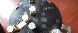
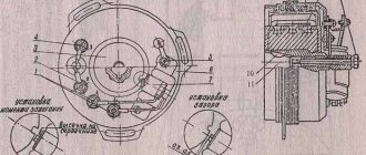
On the generator stator cover there are terminals: - charging coils of the power supply circuit of the Voskhod ignition storage capacitor; — direction indicators; — brake signal; — lighting; — sensor.
Which are marked accordingly: >, >, >, > and >.
The sensor is mounted on the generator stator cover using screws.
Generator rotor
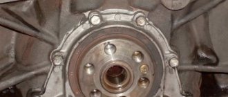
The generator rotor with the sensor rotor located on it is mounted on the right axle axis of the engine crankshaft with a bolt and is secured against rotation by a key.
Switch Voskhod - electronic KET-1
The electronic switch KET-1 is designed to work in the ignition system complete with the G-427 generator and the B-300B high-voltage transformer. Allows you to obtain a secondary voltage of up to 18 kV, at a generator rotor speed of 250 to 7500 rpm. The switch is installed in the right toolbox. The base of the commutator is connected to the ground of the motorcycle. If the switch fails, it can be disassembled and repaired
The electronic switch has three output terminals with letter markings on the body <<Г>>, <<К>> and <<Д>>. The ground terminal is the base of the switch.
Maintaining the switch during operation comes down mainly to tightening the threaded connections, while avoiding stripping the threads. It is necessary to protect the switch from moisture getting inside it and onto the terminals from sudden shocks and exposure to high temperatures. You should also systematically check the reliability of the electrical connection of the switch base with << ground >>, because If this condition is violated, sparking on the spark plug stops.
Return to content
Transmission
During transmission repairs, the following work may be required:
- Adjusting the clutch, replacing its disc and bearing;
- Clutch drive repair;
- Replacement of gearbox bearings;
- Repair of switching module parts;
- Restoration or replacement of gearbox gears.
Most of them require high qualifications and are difficult to do at home. The exception is the repair and replacement of drive mechanisms. So, sometimes there is a need to restore the splines for the gearbox foot, replace the clutch cable or its jacket, or adjust the clutch. These works are carried out without disassembling the crankcase.
Repair and operation of the Voskhod motorcycle are closely interconnected due to the age of the model. However, with the proper approach to organizing and carrying out repairs, the motorcycle will remain your faithful friend and assistant for a long time.
Setting up BSZ Voskhod 3M
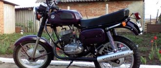
In 1983, the Kavrovsky plant launched the modernized Voskhod 3M motorcycle. The purpose of the modernization was to improve the operational and technical characteristics of the Voskhod motorcycle. The platform for creating the motorcycle was the Voskhod 2M model. Since the early 90s, serial production of the Voskhod 3M 01 modification began. But still, many owners of this device are not satisfied with the appearance. Therefore, in this article we will talk about tuning sunrise 3m.
Transmission
During transmission repairs, the following work may be required:
- Adjusting the clutch, replacing its disc and bearing;
- Clutch drive repair;
- Replacement of gearbox bearings;
- Repair of switching module parts;
- Restoration or replacement of gearbox gears.
Most of them require high qualifications and are difficult to do at home. The exception is the repair and replacement of drive mechanisms. So, sometimes there is a need to restore the splines for the gearbox foot, replace the clutch cable or its jacket, or adjust the clutch. These works are carried out without disassembling the crankcase.
Repair and operation of the Voskhod motorcycle are closely interconnected due to the age of the model. However, with the proper approach to organizing and carrying out repairs, the motorcycle will remain your faithful friend and assistant for a long time.
Supply system
To make the bike go faster, you need to adjust the original carburetor for a higher fuel supply or replace it with a more efficient one. To install a new carburetor, you need to perform the following steps:
- we grind aluminum bushings under the flange of the pipe attaching the carburetor to the cylinders;
- cut off the edge of the inlet channel;
- take a flange from an old carburetor;
- We fasten all the elements using cold welding.
The assembled carburetor must line up exactly with the intake port.
Engine and possible breakdowns
The Voskhod 3m engine is two-stroke, carburetor, single-cylinder. The working volume of the cylinder is no more than 173.7 cm3. Piston diameter/stroke – 62/57.6 mm. Engine power is 15 hp. A used engine in working condition can be purchased for 2000-4000 rubles.
Caring for a sunrise motorcycle generator - how to remove, what to check and install correctly
Generator maintenance mainly comes down to tightening the threaded fasteners of the generator stator and rotor, as well as the wire terminals.
In order to remove the generator, you must:
- disconnect the wires of the ignition circuit, sensor, brake light and direction indicators from the generator terminals;
- unscrew the three screws securing the stator to the crankcase and remove the stator;
- Unscrew the bolt securing the generator rotor and, with light, careful blows of a wooden hammer on opposite sides of the rotor, remove it from the trunnion and remove the key.
Checking the removed parts
After removing the generator stator and rotor, wash the parts with clean gasoline and carefully inspect them. Disassemble the wire fastening terminals on the stator. Wipe dry all insulating parts of the terminals.
Generator installation
Installation is carried out in the reverse order, in this case it is necessary:
- check the runout of the generator rotor, which should be no more than 0.1 mm with the bolt secured;
- tighten the generator stator without distortions, ensuring a tight fit to all three supports;
- install the ignition correctly;
- The generator wires must be securely fastened and well insulated from each other.
Motorcycle ignition installation sunrise
The electrical equipment of the Voskhod 2m motorcycle includes a G-427 generator, a KET-1 switch, a high-voltage transformer, a headlight, central and other switches.
Generator Voskhod G-427
Generator G-427 alternating current with excitation from a permanent magnet with an inductive sensor of the electronic ignition system. In the grooves of the stator, made of stamped electrical steel plates, eight coils are placed, which form four independent circuits: - power supply to the ignition storage capacitor; — lighting and sound signal; — direction indicators;
— braking signal.
Voltage regulation in the circuits of lighting loads is carried out according to the principle of parametric regulation, i.e. The winding data of the generator are selected in such a way that as the rotor speed increases, the voltage at the generator terminals changes within certain limits for a certain load. Attaching the generator stator to the engine crankcase provides adjustment of the ignition timing.
On the generator stator cover there are terminals: - charging coils of the power supply circuit of the Voskhod ignition storage capacitor; — direction indicators; — brake signal; — lighting;
— sensor.
Which are marked accordingly: >, >, >, > and >.
The sensor is mounted on the generator stator cover using screws.
Generator rotor
The generator rotor with the sensor rotor located on it is mounted on the right axle axis of the engine crankshaft with a bolt and is secured against rotation by a key.
Caring for a sunrise motorcycle generator - how to remove, what to check and install correctly
Generator maintenance mainly comes down to tightening the threaded fasteners of the generator stator and rotor, as well as the wire terminals.
In order to remove the generator, you must:
- disconnect the wires of the ignition circuit, sensor, brake light and direction indicators from the generator terminals;
- unscrew the three screws securing the stator to the crankcase and remove the stator;
- Unscrew the bolt securing the generator rotor and, with light, careful blows of a wooden hammer on opposite sides of the rotor, remove it from the trunnion and remove the key.
Checking the removed parts
After removing the generator stator and rotor, wash the parts with clean gasoline and carefully inspect them. Disassemble the wire fastening terminals on the stator. Wipe dry all insulating parts of the terminals.
Generator installation
Installation is carried out in the reverse order, in this case it is necessary:
- check the runout of the generator rotor, which should be no more than 0.1 mm with the bolt secured;
- tighten the generator stator without distortions, ensuring a tight fit to all three supports;
- install the ignition correctly;
- The generator wires must be securely fastened and well insulated from each other.
Ignition adjustment Voskhod
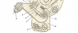
The ignition timing is set by turning the generator stator after first loosening the three screws securing the stator to the crankcase. For normal engine operation, it is necessary that the moment of spark formation (on the generator, this moment is determined by the coincidence of the sensor rotor groove with the protrusion on the sensor coil frame. Fig.) coincides with the moment when the piston does not reach the top dead center of 2.5-3.0 mm (at running the engine on gasoline with an octane rating of 92).
The gap between the rotor and the core of the sensor coil should be within 0.3±0.05mm.
The gap should be set as follows:
- loosen the screws securing the sensor stator to the generator stator cover;
- By moving the sensor stator in the grooves of the generator stator cover, set the required gap, and then tighten the fastening screws.
For more accurate ignition installation, it is recommended to determine the piston position with the cylinder head removed.
Coil Voskhod - high-voltage transformer B-300B
The high voltage transformer is located under the fuel tank and is used to convert low voltage current into high voltage current. The transformer consists of a core, primary and secondary windings, a housing and a cover with terminals. During operation it does not require maintenance and cannot be repaired.
Switch Voskhod - electronic KET-1
The electronic switch KET-1 is designed to work in the ignition system complete with the G-427 generator and the B-300B high-voltage transformer. Allows you to obtain a secondary voltage of up to 18 kV, at a generator rotor speed of 250 to 7500 rpm. The switch is installed in the right toolbox. The base of the commutator is connected to the ground of the motorcycle. If the switch fails, it can be disassembled and repaired
The electronic switch has three output terminals with letter markings on the body >, > and >. The ground terminal is the base of the switch.
Maintaining the switch during operation comes down mainly to tightening the threaded connections, while avoiding stripping the threads. It is necessary to protect the switch from moisture getting inside it and onto the terminals from sudden shocks and exposure to high temperatures. You should also systematically check the reliability of the electrical connection of the switch base with >, because If this condition is violated, sparking on the spark plug stops.
Schematic diagram of an electronic switch
D1-D226B, D2-D226B, D3-D226B, D4-D817V, D5-D817B, D6-KU201L. C1 - 1 µF 250 V, C2 - 1 µF 160 V, C3 - 1 µF 160 V. R1 - 100 ohm, R2 - 1 com.
Point G - 45 volts, Point K - 150 volts, Point D - 0.65 volts.
Throttle type DR-100
Installed in the right tool box. From the generator braking signal circuit, through the throttle, which is a device that complements the parametric control of the generator, the circuit of the speedometer, city driving and license plate lighting lamps is powered.
Spark plug Voskhod - spark ignition type A-23
During operation, the spark plug must be periodically cleaned of carbon deposits and the gap between the electrodes must be adjusted, which should be within 0.6-0.7 mm, which is ensured by bending the outer electrode. To seal, a copper-asbestos gasket is placed between the spark plug and the cylinder head. To eliminate radio interference created by the ignition system, a shielded tip of type A-4 is placed on the spark plug.
Ignition adjustment Voskhod
The ignition timing is set by turning the generator stator after first loosening the three screws securing the stator to the crankcase. For normal engine operation, it is necessary that the moment of spark formation (on the generator, this moment is determined by the coincidence of the sensor rotor groove with the protrusion on the sensor coil frame. Fig.) coincides with the moment when the piston does not reach the top dead center of 2.5-3.0 mm (at running the engine on gasoline with an octane rating of 92).
The gap between the rotor and the core of the sensor coil should be within 0.3±0.05mm.
The gap should be set as follows:
- loosen the screws securing the sensor stator to the generator stator cover;
- By moving the sensor stator in the grooves of the generator stator cover, set the required gap, and then tighten the fastening screws.
For more accurate ignition installation, it is recommended to determine the piston position with the cylinder head removed.
Spark plug Voskhod - spark ignition type A-23
During operation, the spark plug must be periodically cleaned of carbon deposits and the gap between the electrodes must be adjusted, which should be within 0.6-0.7 mm, which is ensured by bending the outer electrode. To seal, a copper-asbestos gasket is placed between the spark plug and the cylinder head. To eliminate radio interference created by the ignition system, a shielded tip of type A-4 is placed on the spark plug.
Supply system
To make the bike go faster, you need to adjust the original carburetor for a higher fuel supply or replace it with a more efficient one. To install a new carburetor, you need to perform the following steps:
- we grind aluminum bushings under the flange of the pipe attaching the carburetor to the cylinders;
- cut off the edge of the inlet channel;
- take a flange from an old carburetor;
- We fasten all the elements using cold welding.
The assembled carburetor must line up exactly with the intake port.
Engine and possible breakdowns
The Voskhod 3m engine is two-stroke, carburetor, single-cylinder. The working volume of the cylinder is no more than 173.7 cm3. Piston diameter/stroke - 62/57.6 mm. Engine power is 15 hp. A used engine in working condition can be purchased for 2000-4000 rubles.
The sore point of all Voskhod 3m is the rapid burnout of the bobbins, which have to be changed with constant use of the motorcycle, about 4 times a year. The chain tensioner also requires constant replacement - with aggressive driving it quickly breaks down. As for the engine, all the troubles that can arise with it are associated with the piston. Installing new rings or completely replacing the piston solves most problems.
Ignition switch Voskhod - central switch
Switch 124005490201 is used as a central software switch that provides the necessary switching of lighting equipment on a motorcycle. The switch has three operating positions >, >, > in accordance with the following operating modes:
- in position > - the generator sensor circuit is shorted to ground, which ensures the engine stops.
- in the > position (driving during the day) - the ignition circuit is turned on, the direction indicator circuit operates (when the direction indicator switch is on) and the brake signal circuit (when the brake pedal is pressed);
- in position > (driving at night), two circuits are switched on:
- a) a circuit of speedometer backlight lamps, license plate lighting and city driving (through a throttle, which serves as a device that complements the parametric control of the generator);
- b) headlight lamp circuit A6-32+32 (via the light switch on the steering wheel).
Caring for the central switch comes down to periodically checking the reliability of the switch in the headlight and cleaning the moving and fixed contacts from dust and dirt by washing them in gasoline.
How to set the ignition at sunrise 3m
The electrical equipment of the Voskhod 2m motorcycle includes a G-427 generator, a KET-1 switch, a high-voltage transformer, a headlight, central and other switches.
Caring for a sunrise motorcycle generator - how to remove, what to check and install correctly
Generator maintenance mainly comes down to tightening the threaded fasteners of the generator stator and rotor, as well as the wire terminals.
Coil Voskhod – high-voltage transformer B-300B
The high voltage transformer is located under the fuel tank and is used to convert low voltage current into high voltage current. The transformer consists of a core, primary and secondary windings, a housing and a cover with terminals. During operation it does not require maintenance and cannot be repaired.
Switch Voskhod – electronic KET-1
The electronic switch KET-1 is designed to work in the ignition system complete with the G-427 generator and the B-300B high-voltage transformer. Allows you to obtain a secondary voltage of up to 18 kV, at a generator rotor speed of 250 to 7500 rpm. The switch is installed in the right toolbox. The base of the commutator is connected to the ground of the motorcycle. If the switch fails, it can be disassembled and repaired
The electronic switch has three output terminals with letter markings on the body >, > and >. The ground terminal is the base of the switch.
Maintaining the switch during operation comes down mainly to tightening the threaded connections, while avoiding stripping the threads. It is necessary to protect the switch from moisture getting inside it and onto the terminals from sudden shocks and exposure to high temperatures. You should also systematically check the reliability of the electrical connection of the switch base with >, because If this condition is violated, sparking on the spark plug stops.
Spark plug Voskhod - spark ignition type A-23
During operation, the spark plug must be periodically cleaned of carbon deposits and the gap between the electrodes must be adjusted, which should be within 0.6-0.7 mm, which is ensured by bending the outer electrode. To seal, a copper-asbestos gasket is placed between the spark plug and the cylinder head. To eliminate radio interference created by the ignition system, a shielded tip of type A-4 is placed on the spark plug.
Headlight Voskhod FG – 133
During operation it does not require special care. Basically, caring for the headlight comes down to removing dust from the internal cavity of the optical element by blowing air.
Source: https://o-ladagranta.ru/kak-nastroit-zazhiganie-na-voshode-3m/
Switch P-200
Light switch with horn button (located on the left side of the steering wheel). To switch the low and high beam circuit, a P-200 type switch is used with a built-in push-button horn switch for three operating positions: neutral - the headlight lamp is off; far right - low beam is on; far left - high beam is on.
The horn button has a movable contact connected to ground and a fixed contact connected to one of the wires coming from the horn terminal. When you press the button, the contacts close and the signal circuit is completed.
Voskhod motorcycle ignition and electrical equipment
The electrical equipment of the Voskhod 2m motorcycle includes a G-427 generator, a KET-1 switch, a high-voltage transformer, a headlight, central and other switches.
Caring for a sunrise motorcycle generator - how to remove, what to check and install correctly
Generator maintenance mainly comes down to tightening the threaded fasteners of the generator stator and rotor, as well as the wire terminals.
Coil Voskhod - high-voltage transformer B-300B
The high voltage transformer is located under the fuel tank and is used to convert low voltage current into high voltage current. The transformer consists of a core, primary and secondary windings, a housing and a cover with terminals. During operation it does not require maintenance and cannot be repaired.
Switch Voskhod - electronic KET-1
The electronic switch KET-1 is designed to work in the ignition system complete with the G-427 generator and the B-300B high-voltage transformer. Allows you to obtain a secondary voltage of up to 18 kV, at a generator rotor speed of 250 to 7500 rpm. The switch is installed in the right toolbox. The base of the commutator is connected to the ground of the motorcycle. If the switch fails, it can be disassembled and repaired
The electronic switch has three output terminals with letter markings on the body, and. The ground terminal is the base of the switch.
Maintaining the switch during operation comes down mainly to tightening the threaded connections, while avoiding stripping the threads. It is necessary to protect the switch from moisture getting inside it and onto the terminals from sudden shocks and exposure to high temperatures. You should also systematically check the reliability of the electrical connection of the switch base with >, because If this condition is violated, sparking on the spark plug stops.
Spark plug Voskhod - spark ignition type A-23
During operation, the spark plug must be periodically cleaned of carbon deposits and the gap between the electrodes must be adjusted, which should be within 0.6-0.7 mm, which is ensured by bending the outer electrode. To seal, a copper-asbestos gasket is placed between the spark plug and the cylinder head. To eliminate radio interference created by the ignition system, a shielded tip of type A-4 is placed on the spark plug.
Headlight Voskhod FG - 133
During operation it does not require special care. Basically, caring for the headlight comes down to removing dust from the internal cavity of the optical element by blowing air.
Ignition switch Voskhod - central switch
Switch 124005490201 is used as a central software switch that provides the necessary switching of lighting equipment on a motorcycle. The switch has three operating positions, , in accordance with the following operating modes:
- in position - the generator sensor circuit is shorted to ground, which ensures the engine stops.
- in the position (driving during the day) - the ignition circuit is turned on, the direction indicator circuit operates (when the direction indicator switch is on) and the brake signal circuit (when the brake pedal is pressed);
- in the position (driving at night), two circuits are switched on:
- a) a circuit of speedometer backlight lamps, license plate lighting and city driving (through a throttle, which serves as a device that complements the parametric control of the generator);
- b) headlight lamp circuit A6-32+32 (via the light switch on the steering wheel).
Caring for the central switch comes down to periodically checking the reliability of the switch in the headlight and cleaning the moving and fixed contacts from dust and dirt by washing them in gasoline.
Switch P-200
Light switch with horn button (located on the left side of the steering wheel). To switch the low and high beam circuit, a P-200 type switch is used with a built-in push-button horn switch for three operating positions: neutral - the headlight lamp is off; far right - low beam is on; far left - high beam is on.
The horn button has a movable contact connected to ground and a fixed contact connected to one of the wires coming from the horn terminal. When you press the button, the contacts close and the signal circuit is completed.
Electrical circuit of the Voskhod motorcycle
Central switch. 2. speedometer. 3. Speedometer light. 4. Headlight. 5. Headlight lamp. 6. City driving lamp. 7. Sound signal. 8. Direction indicator lamp. 9. Direction indicators. 10. Direction indicator switch. 11. Electronic switch. (D - sensor terminal, K - ignition coil terminal, G - generator terminal.) 12. Throttle. 13. Relay breaker. 14. Generator. 15. License plate lamp. 16. Brake signal lamp. 17. Rear light. 18. Wire connection block. 19. Brake light switch. 20. Shielded spark plug cap. 21. Spark plug. 22. High voltage wire. 23. Ignition coil. 24. Light switch.
Ignition sunrise 3m generator connection diagram
Electrical circuit diagram of motorcycles Voskhod 3M-01, Sova 175, Sova 200, ZiD 200 Courier and all-terrain vehicle Farmer. This scheme can be applied to the ZiD 200 Tarpan all-terrain vehicle. The difference is insignificant (the Tarpan all-terrain vehicle has two headlights, versus the one shown in the diagram below).
The electrical circuit diagram can be downloaded with a high resolution of 7740x5400.
Markings and characteristics of lamps:
Lamp A12-1.2: voltage - 12 V, power - 1.2 W. Used in light filters for direction indicators and high beams.
Lamp AMN-12-3-1: voltage - 12 V, power - 3 W. Used for speedometer illumination.
Lamp A12-4: voltage - 12 V, power - 4 W. Used in headlight, side light.
Lamp A12-45+40: voltage - 12 V, power - 45 + 40 W, base type - P45t, lamp marking - R2. Used in headlight, high and low beam. It is allowed to use the AKG12-60+55 lamp: voltage - 12 V, power - 60 + 55 W.
Lamp A12-10: voltage - 12 V, power - 10 W. Used in direction indicators.
Lamp A12-21-3: voltage - 12 V, power - 21 W. Used in tail light, brake light.
Lamp A12-5: voltage - 12 V, power - 5 W. Used in rear light, parking light and license plate light.
Alternating current generator 80.3701 with excitation from permanent magnets, installed on motorcycles since 1992, voltage - 14 V, power - 90 W.
The BKS-1MK211 switch is designed to work with generators 26.3701 (6V 45W), G-427 (6V 65W), 43.3701 (12V 65W), 80.3701 (12V 90W), GM-02.02, GM-03.02, R71, 92.3702M-02.02, GM-03.02, R71, 92.3702.
Ignition coil (bobbin), also known as a high-voltage transformer, operating voltage 12 V, marking 2102.3705 TU 37.003.8UO-78
Spark plug A23-1, spark plugs from BOSCH W6BC or W7AC, or N14YC from BRISK can also be used.
Sound signal: voltage - 12 V, marking 12.3721-10. current consumption: 4.0 A; sound pressure level at a distance of 2 m no more than 90. 118; main sound frequency: 350. 450Hz
Source
Planet on ignition from sunrise Sports video
How to connect the ignition from Minsk to Izh-Planeta. Adjusting the gap and some secrets. My channel https://www.yout.
This video does not contain information on its operating condition and figures for fuel consumption, piston stroke, etc. We are not Wikipe.
Ignition from Minsk to Izh Planet 3.
Two petal valves from a Sova motorcycle into a cross-country CheZet 250 type 513 and ignition from a mower. Used.
Quite often, owners of IZH motorcycles install generators with electronic ignition from Minsk motorcycles.
IZH-49 + generator “Minsk” Channel partner - forum “All about IZH-49 motorcycles” https://izh59.borda.ru/
Petrol ignition on an Izh Planet Sport engine Petrol ignition on an engine Minsk https://m.
restoration and refurbishment of Izh PS part 7, introduction of a 7 volt generator from Minsk to the Izh PS engine.
After throwing out the second hall sensor, I decided to pair the contacts with the switch. and in the end I got it.
Ignition adjustment on generators G-427, 43.3701, 80.3701, 431(432).3701, 26.3701 Pay attention to the design of the sensor.
Moto 37 presents a video dedicated to the profitable exchange of a junk motorcycle for a 1977 VOSKHOD motorcycle.
Operation of the Izh Planeta5 (Planet 5) engine with ignition from a Minsk motorcycle. No battery needed.
Contactless ignition Izh Planet / Sport (MPBSZ 1148.3734 WITHOUT coil, Sovek)
The microprocessor contactless ignition system 1148.3734 (MPBSZ) is a logical continuation of the development of electronic ignition. Model 1148.3734, which has no analogues, is designed to work in IZH PLANET motorcycles of all models with a 6 or 12 Volt generator. The microprocessor ignition module allows you to select the desired operating mode of the motorcycle engine by connecting the output wires in a certain sequence. The use of an optical sensor eliminates all the disadvantages of other spark positioning systems. MPBSZ was developed to improve the technical characteristics of the motorcycle due to: - stability and dynamic performance of the engine thanks to the function of automatically changing the ignition timing depending on engine speed; — reducing the toxicity of exhaust gases, fuel consumption and reducing carbon deposits on spark plugs, due to an increase in the inductive phase of the spark; — stable engine starting when the battery voltage decreases; — reducing the labor intensity in servicing the ignition system; - limiting the amount of current and the time it flows through the primary winding of the ignition coil to protect it from overheating and rapid discharge of the battery.
Incendiary physics - advance, distributor and UOZ
How to set the ignition? What is UOZ? Where did the runners rotate in domestic cars? What does the expression “set by spark” mean? - there are many interesting questions to which owners of modern cars may not give the correct answers.
What is ignition timing - also known as ignition timing? Is this some kind of attribute of ancient cars or something unshakable, akin to universal gravity? Most modern car owners are unaware of this. All car systems are controlled by numerous controllers, and therefore timely sparking in the engine cylinders is entirely their responsibility. Meanwhile, a huge number of ancient machines are running around the country, unfamiliar with processors and other chips. Therefore, questions like “How to regulate the SOP?” still sound today.
It's always a pleasure to answer technical questions. But first you have to remember some “incendiary” terms.
Terminology
Ignition distributor
- an electromechanical device that ensures timely supply of high voltage pulses to the spark plugs.
It is often called a distributor
.
Contact and non-contact distributors for rear- and all-wheel drive carburetor VAZ cars
Contact and non-contact distributors for rear- and all-wheel drive carburetor VAZ cars
Ignition advance
- ignition of the working mixture in the cylinder before the compression stroke ends.
Ignition timing (IDA)
— the angle of rotation of the engine crankshaft from the position corresponding to the appearance of a spark on the spark plug until the piston reaches top dead center.
Parts of the cylinder-piston group
Tuning sunrise 3m begins with improving performance characteristics. The maximum speed of the Voskhod 3M motorcycle can be increased by lightening the CPG parts. To do this, we use a milling machine to bore those places that do not affect the strength.
We lighten the connecting rod in the same way. To play it safe, you can find foreign analogues. Next, you need to bore the purge, inlet and outlet channels. This is done in order to better mix and ignite the air-fuel mixture.
Electrical circuit diagram of the Izh Planet Sport motorcycle
Electrical circuit diagram of the Izh Planet Sport motorcycle
Hai! The improved diagram of the Izh Planet Sport motorcycle on vse-o-moto.com is not only striking, but also has a small analytical review. We will talk about what the IzhMash designers did to make this Soviet cross-country iron horse stand out from other Soviet bikes. Note that the electronics of the above-mentioned motorcycle have significantly improved the fixation, as well as the clarity of operation of all switches/switches on the steering part of the bike.
Did you know that Izh Planet Sport is the first bike from Izhevsk that was produced with 12-volt ignition system equipment. Note that most of the electrical equipment in the Izh sports circuit is unified with another Izhevsk motorcycle - “Jupiter 4”. For example, this applies to the generator, direction indicators, speedometer, optical part of the headlight, rear brake, battery, etc.
Among the electronic features of this two-wheeler you can see unprecedented devices. Their presence complicated the scheme of the sports Planet.
Explanations for the Izh Planet Sport motorcycle diagram:
1) Parking light mode lamp.2) Main front light lamp.3) Neutral transmission indicator lamp.4) Resistor.5) Oil pressure indicator lamp.6) Turn signal relay.7) Isolation unit with diodes.8) Light bulb for speedometer dial illumination.9) Motorcycle ignition switch.10) Front direction indicators.11) Headlight on/off switch, as well as emergency motorcycle ignition switch.12) Brake light on/off switch on the handbrake system.13) Relay regulator.14) On/off switch for the neutral gear lamp.15) Indicator lamp for turning on the high beam.16) Indicator lamp for the operation of direction indicators.17) Indicator lamp for turning on and operating the generator.18) A device for reproducing an audio signal.19) Switch between types of lights, as well as direction indicators . There is also a button to turn on the sound signal. 20) Motorcycle spark plug.21) Izh Planet Sport motorcycle ignition coil.22) Brake light on/off switch on the foot brake system.23) Motorcycle generator.24) Battery (battery).25) Fuse.26) Rectifier.27) Oil pressure sensor.28) Rear direction indicators.29) Rear lamp.
(2 ratings, average 5 out of 5)