Braking torque
There is probably no point in talking about the importance of proper brakes on a motorcycle.
But in order for the brakes to work properly, they need to be serviced. This is what we will talk about. There are two types of brakes installed on motorcycles: drum or disc. Mechanical drum brakes are, of course, a thing of the past. Today, advanced disk drives set the tone, but, nevertheless, the “drum”, due to its low cost, will still be used for some time on small-capacity and domestic equipment. In this article (continued) we will look at both designs.
Tenacious archaism
Drum mechanisms were installed on almost all Soviet production motorcycles, which are still quite widely used in the vast expanses of our Motherland, as well as on some imported scooters, small-capacity (125-250 cm3) motorcycles (usually as a rear brake).
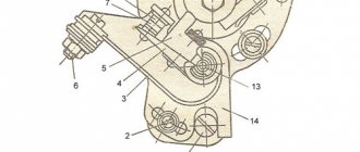
The drum brake (Fig. 1) consists of a drum (1), which is attached to the wheel hub with rivets or is cast with the hub. Outside the drum there are cooling fins. There is a support disk (2) inside. It is fixedly attached to the motorcycle suspension elements (fork leg, pendulum). Two pads (3) with friction linings (4) are mounted on it. The pads are made of steel or aluminum. The task of the linings is to provide good friction, but at the same time be resistant to rapid abrasion, not deform or melt. Previously, the linings were made of asbestos, with inclusions of brass or copper, but nowadays only asbestos-free materials are used. Each block rests against the stop (5) at one end, and against the expansion cam (6) at the other, and they are pulled together by one or two springs (7). The cam is connected with the lever on the steering wheel or the rear brake pedal (9) using levers (8), rods, or a cable.
When you press the lever (or pedal), the cam rotates, pressing on the pad bearings. The pads move apart and are pressed against the drum, braking occurs. If no force is applied, the pads return to their original position under the action of springs. The design is simple and quite reliable, but the single-cam brake does not work at its best. The fact is that when braking, one pad rotates in the direction of rotation of the wheel and is usually called “primary” or “active”, and the other one rotates against rotation, and is called “secondary” or “passive”. And that's why. Let's look at Figure 2. The pads are moved apart by driving forces F1 and F2; let's assume that they are equal. Friction forces R1 and R2 arise between the pads and the drum. The moment of force R1 relative to the block support acts in the same direction as the moment of force F1 and increases the pressing of the primary block. The moment of force R2 is directed in the opposite direction (relative to the moment of force F2) and, therefore, weakens the pressing of the secondary block to the drum. In simple words, the friction force additionally presses the primary shoe against the drum, creating a self-pressing effect, while the secondary shoe “tries” to push itself away from the drum. Hence the main drawback of this design is the large difference in the performance of the pads. Some single-cam brakes have another drawback - the cam presses on the pad thrust bearings at different distances from the center of rotation (the moments of force F1 and F2 are not the same), therefore, again, the pressing forces of the pads are different (Fig. 2).
You can make the brake more “strong” without increasing the size of the drum by using a two-cam mechanism (Fig. 3). At the same time, braking efficiency will increase by 30%. The two-cam brake began to be actively used at the beginning of the second half of the last century as a front brake, the rear one remained single-cam. The brakes of “our” motorcycles were made according to the same scheme: IZH-Jupiter-5, MT-10-36, Dnepr-11, Dnepr-12, Dnepr-16, KMZ-8.157, Java 634 and 638.
The fact is that when a motorcycle brakes, weight is redistributed over the wheels, the front wheel is additionally loaded, so the front brake should be more effective. The two-cam brake is more efficient due to the fact that it has both primary pads (Fig. 3). The drive and synchronization of the two cams is carried out by a lever mechanism.
But all the advantages of the brake can come to naught without proper care and adjustments. Let's start with the fact that every 5000 km all cables and hinges must be lubricated. For this purpose, it is better to use Litol-24 or other greases, but very carefully. After all, excess heated lubricant can get on the pads and drum! The danger is the same as with excess grease in the wheel bearings. If this happens, the drum and pads should be washed in gasoline, but if the linings have absorbed the lubricant to some depth, they should be wiped with emery cloth and then washed in gasoline. The cable should be lubricated with viscous oil or brake fluid. The cable is dipped into a container with oil (for example, MS-20) and the sheath is then moved (5-10 times) along the cable. Let the oil drain and wipe the casing dry.
For the brake to work effectively, it must be adjusted. This is mainly due to wear on the linings.
The single-cam brake of the rear wheel is adjusted by a screw located in the rear wheel sprocket housing (IZH-Jupiter-5, IZH-Planeta-5). On motorcycles “Dnepr” and “Ural” the brake is adjusted using an adjusting cone. The free travel of the pedal is set to 10-15 mm, and the wheel should be blocked at a travel of 75-100 mm.
On a Java 350/368 motorcycle, the rear brake is adjusted by rotating the impeller. The impeller is tightened until the block begins to slow down, and then it is loosened by 1.5 turns. In any case, when the brake is released, the shoes should not touch the drum, and if the position of the pedal can be adjusted, then install it so that it is always under your foot, and you can press it without removing your foot from the footrest.
If a single-cam brake is installed on the front wheel (Fig. 4), as, for example, in the IZH-Jupiter-3, then adjust it with the screw (1) located on the support disk. By screwing it in or out, you should achieve a free play of the end of the lever on the steering wheel of 5-10 mm. If the brake cannot be adjusted in this way and the wheel does not brake, turn the cam lever to 1 spline.
As for two-cam brakes, they are regulated somewhat differently. For example, adjusting the front brake Java 350/638 (Fig. 5). First, loosen the cable impeller (1), then loosen the connecting rod of both shoes (2). Tighten the impeller until the block begins to slow down. Then you should loosen the impeller 1.5 turns. Tighten the connecting rod nut until the pads begin to rub, then loosen it 1.5 turns. Adjust the free play of the control lever (5-10 mm) by rotating the impeller.
But sometimes adjusting the brakes cannot return them to working order; they require repairs.
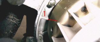
The most common type of repair is replacing the pads. Sometimes new pads are riveted onto old pads. On some motorcycles, the degree of wear of the linings can be monitored by the wear indicator arrow (Fig. 6).
But no matter how simple it may seem to replace the pads, sometimes you have to tinker with them. New linings have a reserve in thickness and do not want to fit into the drum. This is done so that they fit into a worn or bored drum. Therefore, they will have to be cut down, and then, after some running-in, they will rub in and work normally.
Sometimes replacing pads does not lead to the desired result. What is the reason? Most often, deep grooves and risks on the inner surface are to blame. The worn surface is restored by boring and grinding. If the motorcycle has been standing for a long time, rust may appear on the working surface of the drum. It is cleaned with emery cloth and gasoline.
Typically, brake performance decreases gradually as it wears out. But sometimes the brake “disappears” instantly. The most obvious reason is a broken cable. Sometimes the splines on the cam shaft become wrinkled. Brakes can also fail if water gets on the pads. The brake may also jam - this happens when a spring breaks or flies off. Then the primary block, carried by the drum, jams. Sometimes jamming can also occur due to a weak spring and high friction forces in the brake mechanism, but even a “strong” spring will not be able to release the brake if it is not lubricated.
As for drum brakes, their age is over. Motorcycles have become more powerful and dynamic, and the drum brake has fallen behind in power and efficiency, and has passed the baton to the powerful and durable disc brake. With the massive entry of Japanese models into the world market, disc brakes began to rule the roost.
New era
1969 marked the beginning of the release of the Honda CB 750, and it was destined to usher in a new stage in the development of the motorcycle. This was the first mass-produced “Japanese” with an inline “four”. The engine had an overhead camshaft, dry sump, and four carburetors. The engine was started with a starter, which was very rare at that time. No less rare was a five-speed gearbox made in the same unit with the engine and... a front wheel disc brake with a hydraulic drive!
The disc brake was invented by British designer Frederick Lanchester and was first used back in 1903 on a car. Later it was installed as a transmission (parking) brake on trucks and buses. Well, it was first used as wheel brakes in aviation, where it proved excellent due to its efficiency. The first production car to be equipped with disc brakes on all wheels was the Jaguar XK 150 in 1957.
But let's leave cars and planes alone and get back to motorcycles. Of course, before 1969 there were attempts to equip a motorcycle with a disc brake, but these were isolated cases, mainly on sports motorcycles. And in 1967, the MV Agusta 600 motorcycle, also with a disc brake, but with a cable (mechanical) drive, began to be produced in small series. Its effectiveness was so low that it was soon abandoned and they returned to the “drum”. So the Honda CB 750 was the first production motorcycle with an efficient disc brake, which later retired the drum brake. The first Soviet production motorcycle with a front disc brake in 1990 was the IZH-7.107-015 “Planet-5”.
Initially, a disc brake was installed on the front wheel, as it was more effective, while the rear one remained a drum brake, since when braking, up to 75% of the motorcycle’s weight fell on the front wheel. Later, the rear “drum” was replaced with a “disc”, but there was no point in making it as powerful as the front one, so it is much weaker. But a more effective option was to install two discs on the front wheel and a single disc brake at the rear. However, single-disc front brakes are still quite common, as are rear drum brakes. The advantages of disc brakes over drum brakes are obvious.
First, disc brakes cool better and allow the bike to slow down more quickly. Secondly, they are lighter, which reduces unsprung mass and the gyroscopic effect. But to press the pads to the disc, more force is required, and since disc brakes do not have a self-reinforcing effect, like drum brakes, therefore, a hydraulic drive is used in disc brakes. Why hydraulic drive? The thing is that the liquid does not compress; it is easy to transmit force with its help. But the main thing is that in the hydraulic system it is possible not only to transmit force, but also to increase it, thanks to the different diameters of the pistons of the main and working cylinders (Fig. 7).
So, if the diameter of the piston of working cylinder 2 is twice the diameter of the piston of main cylinder 1, then the force will be increased by 4 times. If the diameter of the working cylinder piston is three times larger than the diameter of the master cylinder piston, then the force will increase by 9 times! And so on. But the larger the working cylinder piston is compared to the main cylinder piston, the less it will move relative to the movement of the master cylinder piston. After all, the volume of liquid transferred does not change! However, it is not difficult to make the hydraulic brake drive system such that the movement of the pistons, and even more so, the force will be enough to stop the motorcycle. The main thing is to find the “golden mean” so that the bike stops quickly and the wheel does not lock when you lightly press the brake lever.
Brake fluids “work” in the hydraulic brake drive. Currently, liquids of classes DOT-3, DOT-4, DOT-5 and DOT-5.1 are used.
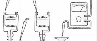
Brake fluids DOT-3, DOT-4 are made on a polyglycol base, and they can be mixed with each other in any proportions; in addition, they absorb moisture, that is, they are hygroscopic. This means that the more water there is in the brake fluid, the lower its boiling point will be. That is why the boiling point of “dry” and moisture-containing liquids is indicated (Table 1). Therefore, a “damp” liquid can boil at the most inopportune moment. A few intense decelerations are enough for compressible vapor bubbles to appear in the incompressible liquid. The brakes will “disappear”, we won’t talk about the consequences...
Liquids DOT-3, DOT-4 and DOT-5.1 are painted yellow to distinguish them from liquid DOT-5, which is made on a silicone base and has a dark red color. DOT-5 cannot be mixed with polyglycol-based brake fluids - a sediment will form. It does not mix with water either. Any brake fluid should be protected from water and dirt getting into it. It “pulls” moisture even from the air, deteriorating its performance over time. Any brake fluid must be changed at least once every two years, and which fluid should be used for a particular motorcycle is decided by the manufacturer.
We will return to the topic of brake fluid (replacing, bleeding brakes), and also consider design options for modern disc brakes, but we will do this in the next issue of the magazine.
Source
A huge hello to everyone! The season is just around the corner, it's time to start preparing the horses for the season. Well, that’s basically what I do... Eh, I didn’t want to do this, but I had to. So you ask, is it being renovated again? I just recently assembled it, ran it in, what else do you need, calm down already!!! Yes, I would be glad, but this meticulousness about the condition of the motorcycle got the better of me and we went all out. I warn you right away, there will be more material and photos than usual)))) This time it’s all in one post. I ask all interested people to “CUT”. How did it all start? Yes, everything is very simple) Last trip to P6 for the season. I arrived at the garage, washed it and dried it. I look at him and see a joint on a joint. Well, there was just something I didn’t like about every centimeter.
I’m standing and thinking whether to disassemble it or not, yes or no... Ahhh, to hell with it, let’s go)) The old, crappy paint job immediately catches your eye. There’s a bit of rust, there’s no show-off tired clamps on the wiring. All wrong!
And what pissed me off the most was that the seal came off again and all the dirt went here. Well, I can’t look at it so calmly when I collected other motorcycles and everything was much better there.
The glove compartments began to rust from the inside due to moisture, old electrolyte and worn rubber bands. And with painting, everything is visible. That's it, take everything apart immediately!
Um, not even 2 hours had passed before everything was disassembled and put into boxes. It’s like a construction set - that’s it)) Just like when I was a child, I assemble Legos) It was during disassembly that I was convinced that this had to be done.
In general, that surprised me. The left shock absorber immediately disintegrated, as the nut on the rod was unscrewed and it was simply held under my weight, and during disassembly it automatically disintegrated. The corrugation of the chain touched the frame and rubbed, again my jamb.
Everything is small, we put all the electrics separately, as usual, all the fasteners. In general, we sort everything out so that later we don’t get confused and confused about what came from where)))
Just like that, that’s it, the motorcycle turned into spare parts. And now the search begins for new spare parts, normal rubber goods and other necessary small things.
We are unfolding in the utility room) We need to put everything away so that it doesn’t get in the way underfoot in the garage. Yes, and you still need to disassemble small parts for painting. It's pure pleasure.
Well, everything is ready for painting. And I took this case literally 2 days later, having previously cooked a couple of places where local conflicts were brewing.
Along the way, I disassembled the fork legs and shock absorbers for inspection. It was necessary to understand what had come to an end...
And then some nice things began to be acquired)))) Little by little, I began to find what I needed.
I found a new pendulum of a new type (which I should have), also a brake pedal and linkage and everything is brand new, oooh, cool! And most importantly, we found the ORIGINAL intake pipe from Planet 6, which will eliminate the problem with carburetor tilt.
Another joy is the chrome-plated shock absorber cups. Also new))
I couldn’t miss the opportunity to take new original wiring, although it was slightly tied off with blue electrical tape... Also, the caps on the plug were caught. It’s already good, everything is starting to gain momentum.
Well, I need this too! Mudguards, a hydraulic hose, and especially housings for an enlarged filter and much needed small items. Wow, I'll collect it now)))
I also purchased the necessary rubber goods and other small items. And all this will come in handy. I can already imagine how it will all look... everything will be gorgeous!
You can start assembling... Let me start with the shock absorbers and forks. I’m already used to starting work with them) Everything is clean, I love it when everything is so neat and new. Know just collect)
Clap! Like from the factory)) New 
We take on the passenger footrests. They were also painted and when the legs are turned, the coating does not scratch and looks decent. Initially, I wanted to send such parts for electroplating, but there is no access to it, and the price tags are high. So even after painting they look no worse.
Finished with the fork legs, shock absorbers and all the footpegs. The pendant is ready for work and defense, and now the main part can be assembled.
Freshly painted frame. I've been waiting for this for so long)
2.5 hours. It took 2.5 fucking hours to press and unroll the bushing under the brake pedal! As you know, before me the owner did not pay much attention to this and successfully lost the bushing and the pedal was dangling stupidly and the hole was bent. For now I leveled it with a drill, then with a round file. And only then did the bushing just go in. I have long thought that there should be a bushing here, but I missed this point before assembly. Having measured the diameter, it turned out that the bushing here fits from the connecting rod of the planet. While I pressed it in, I unrolled it with 3 reamers and finalized it. Phew, honestly, I got tired here, but in the end I won.
Trying on the pedal. Having generously lubricated the pedal shaft with grease, I checked for play. It was minimal. YES! This is exactly what needed to be achieved! Now you can rest assured about this node. That's how much time it takes to fix bugs.
And then along the lines)) The pendulum with shock absorbers, passenger handles and footrests fell into place. Everything is so neat, I like it.
So the native traction fell into place. Before this, it was homemade from an ordinary round one. Some people say that it’s inconvenient to use the brakes, but I’ll find out later...
Turn holders. Finally they have been found! Without them, the Orion turn signals are difficult to attach here, since the length of the thread is short, plus the groove does not allow them to sit all the way. And so I simply inserted the turn signals into them, tightened them, adjusted them and that’s it. And I learned this quite recently, leafing through the catalog. Until this time, since 2009, I had to file off the grooves and somehow tighten the turns))) Live forever and learn.
Front line. We press in new races and install bearings, also lubricating them generously)
So the feathers fell into place. At the same time, the rubber bands in the upper traverse were replaced, and in general everything was replaced))
Beauty... I polished all the clamps, turn holders and fasteners before installation)) This time I used native fasteners from Izhevsk. I completely decided to get confused) I really wanted it to look like new. The fasteners were already almost like new, but the shine needed to be added.
We can continue further) I think it’s time to install glove compartments...
Wow, handsome guys) New RTI. Later, it will still be necessary to make improvements to eliminate the cracks so that dirt and water do not fly in when washing.
Ready! At the same time, the turns fell into place.
I decided to put round turns and “potatoes” on the front. From the front they are prettier to me than the Orion ones. Orionovskys look like mugs to me personally, I don’t want to offend any of the Izhatnikov)
The cases are also painted, and I found new pieces of glass from a friend. There were supplies from my grandfather, everything was covered in dust and dirt from storage, so he gave it to me)) Well, overall it seems nice...
So the tidy fell into place along with the ignition switch. By the way, the plastic housing of the ignition switch was also, out of stupidity, looking for the original one)) On the remake, the numbers “1 and 2” and “off” are simply stamped, but on the original ones they are also painted with enamel. Again my troubles)
Rear casing)) Beautiful. There is no point in showing how I assembled it, since it was in another part. Here I just stuffed more grease into the bearings and that’s it, and the sprocket, pads and chain were in excellent condition after 2 years of use. A plus to their chewiness was the tightness of the casings and the presence of abundant lubrication. By the way, the clamps on the rubber casings are also original after polishing)) Otherwise, I somehow don’t want to install ordinary plastic ones...
Look more or less. So I decided to figure out the new wiring, check if everything fits in length and connectors, otherwise anything can happen.
The steering wheel began to acquire remote controls, knobs and new mirrors. True, the remote controls had to be soldered a little under the factory wiring and the excessively long wires had to be shortened and heat-shrinkable on the terminals for tightness. It was no coincidence that I wanted to change the mirrors, my original mirrors were just SICK of me! I'm tired of setting them up every time and looking around when changing lanes to be sure. And these have a great view and don’t rattle when driving. Such mirrors were on Planet-5, which I assembled in the summer, and that’s where I liked them. Fuck this original, I'm talking about mirrors. In this case, better visibility and safety play a role for me.
Caliper) Also after painting. I assembled it with new cuffs and fasteners, almost like new)) But it was shabby from a hard life...
Well, the motorcycle is gradually acquiring everything necessary.
I rummaged through my bins and found the anthers for the plugs. I picked up and put boots on almost all the connections, otherwise I don’t want dirt and water flying there.
Wah! We are going the right way...
Trying on the original intake pipe. HOORAY! Now the carburetor will stand straight!!! It's really lucky that I found him. But the carburetor casings had to be modified to accommodate it. With the engraver it took 2 hours. And after 2 hours, the excess walls were removed from the casings so that everything fits neatly on the crankcase and does not rest against anything. At the same time I removed the engine cover to check the chain. Everything was fine, this is purely for personal peace of mind, so as not to open it later.
Here is the engine in its place. We securely fasten it and for fitting we put on the carburetor, adapter and enlarged filter.
Hallelujah!!! Everything fit perfectly, but I was worried that there wouldn’t be enough space for the filter. Still, after the pipe there was a rubber adapter from IZh PS to Mikuni, an adapter for the carburetor, the carburetor itself and a filter. And this entire structure took up all the free space and fit perfectly into the landscape.
Now we put the chain on the engine sprocket and close the lid so that it does not interfere with us for now.
And now we need to lay out all the wiring according to Feng Shui, so that nothing hangs.
Before laying the wiring, I forgot about the cables... In theory, this should all be done together, especially in the place above the engine.
Taking hold of the cables, I saw that the throttle cable had come to an end. The cable itself was kinked and was rubbing against the guide on the remote control and did not really work. Well... We will treat. We take out the old cable, before that we measured the cable outlet and the boss, inserted a new cable and cut the length and soldered the boss. Hmm, I even had to get into the cables, since such cables are not sold for the divider... In the end, everything worked out) And of course, I pumped grease into all the cables to make it work better.
I cleaned the oil tank, stretched the cable, and adjusted the tension so that oil would flow immediately. In general, the separate lubrication is ready)
I put on the oil hose and connected the sensor. This time, even here, I laid out the wiring and secured it with a special clip that was on the engine. Everything immediately became so neat.
And now we stretch everything out so that it doesn’t get in the way or pinch anywhere. It’s too early to secure it, but at least nothing is loose.
And we fasten everything on the steering wheel and tighten it with clamps.
I secured the RNM-1 and remembered that it was almost always hellishly dirty here. And I didn’t like it, I had to come up with something so that dirt wouldn’t fly through the cracks... Well, that’s not the case when everything here is dirty, especially the electrician and the BPV, which needs cooling, and not a hat made of mud.
That's what I came up with. I found a roll of some kind of thing, I don’t even know what to call it, a sealant or something. As a result, I first wound the 2nd layer from the engine on the sides, from the edge of the glove compartment to the other edge and on top of the fender, along the fender and under the mount outward. Of course, I secured everything with bolts and wide washers so that it wouldn’t move but would stay in place. I also made a small roll of this thing on top of the wing and slipped it under the 2nd layer, so that when you put on the saddle, it would flatten a little and be hermetically sealed between the saddle and the frame, so that nothing would fly from above. In the final version, the huge cracks have closed and where dirt used to fly is now impossible to get through. Finally solved this problem)
Then I cleaned and inserted the filter. Now all the space near the wing was occupied, all that remains is to pour oil into it and it will be fine)
Well, all the electronics are in their place, in a clean place!
I put on the modified carburetor casings, now everything fits completely and nothing is pinched anywhere. Good)
I added the wiring and attached it to clamps with a lining so that it would not rub the frame. There will be such pads for the clamps on the entire frame, otherwise without them the clamps will wear through the enamel to the bare metal.
The same thing here, we stretched everything, left a reserve so that everything would not be too tight, and secured it. Now the cables, divider and wiring are laid out and we can move on. I'm done with one tedious task.
In the meantime, the casting went to beading and painting, since in some places the enamel had already fallen off. The years have taken their toll... After beading, everything was cleaned, degreased and painted using pulverized paint. For some reason I didn’t want to take the wheels to powder.
After a little time, the wheels were installed. I immediately lubricated all the bearings in the hubs. On the front casting I also changed the seals. Now it looks different. There is some penetration of enamel through the masking tape in some places, but then carefully remove this with fine sandpaper and go over it with a felt boot with GOI paste so that there are no marks.
I also immediately tightened the chain so that I wouldn’t have to return to it later. On the tensioners, I had to put a nut on each side so that they wouldn’t play when driving, otherwise the standard nuts are placed after the pendulum ears, but I also put them before them. I have noticed more than once that without them, sometimes the axis plays back and forth.
I went through the gearbox, stuffed even more lubricant into it, otherwise experience showed that last time there was not enough of it. In principle, the front end was ready to install the wheel.
Well, finally, the motorcycle is now on wheels and has left the far corner)) Now I pumped the front brakes and adjusted the rear ones.
Now everything in the front worked as before, or even better. Although rather better.
I had to struggle with the rear brake. After adjustment, the pedal rested against the footrest and when pressed, it touched the edge of the muffler... hmm, again we need to think about something.
A new muffler was put in place. For a long time I was looking for a normal, not wrinkled muffler! Now it doesn't spoil the view.
I completely forgot about the frog. Now it’s in place, and the glove compartment container is back. At the same time I solved the problem with the pedal. I changed the fastening of the footpeg, instead of the right one I installed another left one, now nothing rests against it. I also bent the pedal slightly away from the muffler. Now when pressed it does not touch anything and the footrest does not interfere. Well, everything needs to be completed)
I put the radiator back. I replaced all the pillows on the mounts, which I found surprisingly new in the store. In principle, everything is ready here, except for the wiring to the fan. Having hooked everything back up, I saw that the supply of wires was large. I had to work with a soldering iron and re-solder some terminals and hide the wires in heat shrink.
By chance I found a new factory battery strap in the basement, although the mounting ears were for the glove compartment of an IZH PS. In the store I saw a Honda battery strap with the necessary ears. It cost 20 rubles in total, so I bought it just because of the ears) The strap is a little shorter, so I wrapped it around the switch so that it fits more softly to the case, and I inserted the ears into the original strap. I put a seal under the walls, and I also cut it out under the strap to make the corners softer.
Well, now it’s a completely different matter! Chic, shine, beauty.
I brought the saddle from home and checked the operation of the stop and light. I also finally adjusted the steering wheel, mirrors and switching panels so that everything was comfortable for my seating position.
And here's a surprise! I decided to check the spark and charging. The engine fired up, the charging is excellent, there is no spark. Hmmm... Again the same nonsense as during the last assembly. Although everything was there before the analysis. I reconnected the switch, but to no avail. Baaalin, I went home to get the rotors, in case there was a problem with them. I moved a couple of things, again no spark. I went and picked up the stators. Just for fun, I installed the stator and rotor with which last time nothing worked, nothing at all, although they were new and had never been used. I installed it - everything is there! Charging, the spark that kills the elephant, too. Amazing system, sometimes it works, sometimes it doesn't. The ignition is good, but it always blows my mind during assembly! In some article in the MOTO magazine there was material about this ignition and the headline said that IZHMash had made a big leap in the ignition system, but for some reason such hemorrhoids just sparked, it seemed like everything was the same, but it didn’t work, but then boom it works! After the final installation, I checked everything again and everything worked, poof... One less problem.
And at this moment we could say that everything was ready. Everything is collected, everything is checked. Nno, I couldn’t get the idea out of my head that the cladding needed to be painted.
Everything looks great, yes. But the inside of the tank and glove compartment lids were terrible, since spray painting without varnish is all nonsense. And besides, I decided to get rid of the stickers, thought about it and decided that it was unnecessary. Still, they were accidentally touched once and scratched, and if you wash the dirt off the moto, they also get a little scratched.
Well, here he is, handsome) After a test drive. Then I washed it from all the dust and dirt, and thought - I’ve finally finished this whole thing) However, there is one big nuance - my frame is like that of a regular Planet 5-01, and therefore the tank is raised a little so as not to lie on the radiator. Ideally, you need a frame from the 2000s Planet 5, which has a changed steering column angle. With it, the tank will be installed as it should and will be perfect. In general, guys, what if your friends have a frame that is not needed from the planet with a different tilt of the steering column, then write - it will help out a lot, of course, not for free. Even if you sell the whole bike - write)))
And finally, some photos of the final result.
This point sums up this whole bulkhead project. Yes, the bulkhead was really needed so that now, having all the strength and means, I could bring this motorcycle to excellent condition. It took a lot of time, but the result is worth it. And now you can drive for your own pleasure and not think that you need to fix something or anything else. Now all you have to do is do the maintenance in a timely manner and find normal pistons for the future, when the nominal value will have to be changed. Someone might think that I’m a maniac for spending so much time on the same motorcycle. Well... everyone has their own cockroaches, and I enjoy doing this business
With this I say goodbye, see you soon) There will be another post soon about the completion of work on Jupiter-5. Have a calm start to the season everyone, don’t forget to prepare your horses and ride carefully)))
Front Brake Adjustment
1. Place a blank under the engine crankcase so that the front wheel does not touch the ground.
2. Unscrew locknut 1 (Fig. 31) of adjusting screw 2 several turns.
3. Rotate the adjusting screw until you obtain a free play of the brake lever equal to one third of its full travel. When the adjusting screw is screwed in, the free play of the lever increases, and when turned out it decreases.
4. Check the adjustment in place and while the motorcycle is running.
5. Lock the adjusting screw.
In the event that further unscrewing of the adjusting screw is impossible, adjust the front brake in the following order:
1. Unscrew the locknut of the adjusting screw until it fails.
2. Tighten the adjusting screw to three-quarters of its length.
3. Loosen bolt 3 holding the brake cable to the brake lever.
4. Pull the cable and secure it to the lever with a bolt.
5. Adjust the brake using the adjusting screw.
Rear brake adjustment
1. Place the motorcycle on the rear stand.
2. Unscrew the locknut 5 (Fig. 30) of the adjusting fork 6 of the left brake rod.
3. Unscrew the nut of the bolt securing spring 7 of the brake light switch to the brake rod, disconnect the spring from the rod.
4. Unscrew and remove connecting pin 8 of the left brake rod.
5. By rotating the adjusting fork, adjust the length of the rod so that, when put in place, it provides free play of the brake pedal equal to one quarter of its full travel.
6. Replace the rod with the adjusting fork and the connecting pin and tighten the lock nut of the adjusting fork.
Attach the brake light switch spring to the brake rod so that the brake light comes on when braking begins.
7. Check the results of the adjustment in place and while the motorcycle is running.
Note. If it is impossible to adjust the brake by changing the length of the left rod, then the right brake rod, which has an adjusting fork at the rear end, should be additionally shortened or lengthened.
ADJUSTING WHEEL BEARINGS
The adjustment should ensure free rotation of the wheel without play in the bearings.
Front wheel
1. Place the motorcycle on the rear stand. Place a blank under the engine crankcase so that the front wheel does not touch the ground.
2. Unscrew and unscrew the left nut 1 (Fig. 32) of the wheel axle.
3. Bend the edges of lock washer 2 and unscrew locknut 3 on the left side of the axle.
Rice. 32. Adjusting the front wheel bearings:
1 - wheel axle nut; 2 - lock washer; 3 - lock nut; 4-hub bushing nut; 5-adjusting nut
4. Holding the bushing nut 4 on the right side of the wheel hub with a wrench, tighten the adjusting nut 5 on the left side until the play in the bearings is eliminated. The wheel should rotate freely on the axle.
5. Tighten the locknut and axle nut. Bend the edges of the lock washer and tighten the axle nut.
6.Check the adjustment results; When the wheel rocks sideways, there should be some play and the wheel should rotate freely.
Rear wheel
1. Place the motorcycle on the rear stand.
2. Unscrew nut 1 (Fig. 33) of the wheel axle by six to seven turns.
3. Bend the edges of the lock washer 2 of the adjusting nut 3 (on the right side of the wheel hub).
4. Hold the adjusting nut with a wrench and unscrew locknut 4 one or two turns.
Rice. 33. Adjusting the rear wheel bearings:
1-wheel axle nut; 2-lock washer; 3- adjusting nut; 4-lock nut
5. Tighten the adjusting nut until the play in the bearings is eliminated. The wheel should rotate freely on the axle.
6. Hold the adjusting nut with a wrench, tighten the locknut and bend the edges of the lock washer.
7. Tighten the wheel axle nut.
8. Check the result of the adjustment: when the wheel rocks sideways, there should be no play, and the wheel should rotate freely.
Single-post wooden support and methods for strengthening corner supports: Overhead line supports are structures designed to support wires at the required height above the ground and water.
Transverse profiles of embankments and coastal strips: In urban areas, bank protection is designed taking into account technical and economic requirements, but special importance is given to aesthetic ones.
Papillary patterns of the fingers are a marker of athletic abilities: dermatoglyphic signs are formed at 3-5 months of pregnancy and do not change throughout life.
Source
Front Brake Adjustment
1. Place a blank under the engine crankcase so that the front wheel does not touch the ground.
2. Unscrew locknut 1 (Fig. 31) of adjusting screw 2 several turns.
3. Rotate the adjusting screw until you obtain a free play of the brake lever equal to one third of its full travel. When the adjusting screw is screwed in, the free play of the lever increases, and when turned out it decreases.
4. Check the adjustment in place and while the motorcycle is running.
5. Lock the adjusting screw.
In the event that further unscrewing of the adjusting screw is impossible, adjust the front brake in the following order:
1. Unscrew the locknut of the adjusting screw until it fails.
2. Tighten the adjusting screw to three-quarters of its length.
3. Loosen bolt 3 holding the brake cable to the brake lever.
4. Pull the cable and secure it to the lever with a bolt.
5. Adjust the brake using the adjusting screw.
Rear brake adjustment
1. Place the motorcycle on the rear stand.
2. Unscrew the locknut 5 (Fig. 30) of the adjusting fork 6 of the left brake rod.
3. Unscrew the nut of the bolt securing spring 7 of the brake light switch to the brake rod, disconnect the spring from the rod.
4. Unscrew and remove connecting pin 8 of the left brake rod.
5. By rotating the adjusting fork, adjust the length of the rod so that, when put in place, it provides free play of the brake pedal equal to one quarter of its full travel.
6. Replace the rod with the adjusting fork and the connecting pin and tighten the lock nut of the adjusting fork.
Attach the brake light switch spring to the brake rod so that the brake light comes on when braking begins.
7. Check the results of the adjustment in place and while the motorcycle is running.
Note. If it is impossible to adjust the brake by changing the length of the left rod, then the right brake rod, which has an adjusting fork at the rear end, should be additionally shortened or lengthened.
ADJUSTING WHEEL BEARINGS
The adjustment should ensure free rotation of the wheel without play in the bearings.
Front wheel
1. Place the motorcycle on the rear stand. Place a blank under the engine crankcase so that the front wheel does not touch the ground.
2. Unscrew and unscrew the left nut 1 (Fig. 32) of the wheel axle.
3. Bend the edges of lock washer 2 and unscrew locknut 3 on the left side of the axle.
Rice. 32. Adjusting the front wheel bearings:
1 - wheel axle nut; 2 - lock washer; 3 - lock nut; 4-hub bushing nut; 5-adjusting nut
4. Holding the bushing nut 4 on the right side of the wheel hub with a wrench, tighten the adjusting nut 5 on the left side until the play in the bearings is eliminated. The wheel should rotate freely on the axle.
5. Tighten the locknut and axle nut. Bend the edges of the lock washer and tighten the axle nut.
6.Check the adjustment results; When the wheel rocks sideways, there should be some play and the wheel should rotate freely.
Rear wheel
1. Place the motorcycle on the rear stand.
2. Unscrew nut 1 (Fig. 33) of the wheel axle by six to seven turns.
3. Bend the edges of the lock washer 2 of the adjusting nut 3 (on the right side of the wheel hub).
4. Hold the adjusting nut with a wrench and unscrew locknut 4 one or two turns.
Rice. 33. Adjusting the rear wheel bearings:
1-wheel axle nut; 2-lock washer; 3- adjusting nut; 4-lock nut
5. Tighten the adjusting nut until the play in the bearings is eliminated. The wheel should rotate freely on the axle.
6. Hold the adjusting nut with a wrench, tighten the locknut and bend the edges of the lock washer.
7. Tighten the wheel axle nut.
8. Check the result of the adjustment: when the wheel rocks sideways, there should be no play, and the wheel should rotate freely.
Transverse profiles of embankments and coastal strips: In urban areas, bank protection is designed taking into account technical and economic requirements, but special importance is given to aesthetic ones.
Papillary patterns of the fingers are a marker of athletic abilities: dermatoglyphic signs are formed at 3-5 months of pregnancy and do not change throughout life.
Organization of surface water flow: The largest amount of moisture on the globe evaporates from the surface of the seas and oceans (88‰).
Source
the rear brake does not work.
the rear brake does not work.
Post by seva722 » May 10, 2012, 11:27 pm
Re: Rear brake not working.
Post by Detonator » May 10, 2012, 11:42 pm
Loosen the adjusting screw at the back in the sprocket housing, make sure that the pad release roller is clearly horizontal. Place adjusting washers under the heels. Degrease the pads and go over them with sandpaper or a file. You can make a notch on the pads. Remove the star casing and unscrew it. Wash inside. Make sure that when squeezing, the pressure roller does not warp due to wear. Lubricate. Make sure that with the spring pads installed and the expansion part of the roller in a horizontal position, the lever sitting on its slots (the adjusting screw passes through it) is installed as close as possible to the rear edge of the casing, to the hole for the plug. If not, rearrange. Lubricate the lever bushing on the pendulum. In general, lubricate everything, eliminate play everywhere. Including on traction. After this, assemble everything on the motorcycle, set the chain tension, select the free play of the brake pedal with the adjusting screw, and test the brake operation.
Large wear on the expansion roller is treated by a welder and a turner.
Re: Rear brake not working.
Post by seva722 » May 10, 2012, 11:58 pm
Re: Rear brake not working.
Post by android » May 11, 2012, 00:14
Re: Rear brake not working.
Post by Detonator » May 12, 2012, 8:23 pm
Re: Rear brake not working.
Post by Dimons594 » 12 May 2012, 21:12
Re: Rear brake not working.
Post by seva722 » May 12, 2012, 10:33 pm
Detonator wrote: Loosen the adjusting screw at the back in the sprocket housing, make sure that the roller that releases the pads is clearly horizontal. Place adjusting washers under the heels. Degrease the pads and go over them with sandpaper or a file. You can make a notch on the pads. Remove the star casing and unscrew it. Wash inside. Make sure that when squeezing, the pressure roller does not warp due to wear. Lubricate. Make sure that with the spring pads installed and the expansion part of the roller in a horizontal position, the lever sitting on its slots (the adjusting screw passes through it) is installed as close as possible to the rear edge of the casing, to the hole for the plug. If not, rearrange. Lubricate the lever bushing on the pendulum. In general, lubricate everything, eliminate play everywhere. Including on traction. After this, assemble everything on the motorcycle, set the chain tension, select the free play of the brake pedal with the adjusting screw, and test the brake operation.
Adjusting the front brake IZH Jupiter 5
Motorcycle IZH-Planet. Operation, maintenance and repair. >> Front wheel, front brake. Front wheel hub - disassembly and assembly
LLC "World of Autobooks"
Front wheel hub - disassembly and assembly
Disassembly
1. Remove the front wheel (see above) and place it with the brake cover facing up.
2. Remove the brake cover with pads.
3. Using a soft metal drift, carefully knock out the driven (worm) gear of the speedometer cable drive.
4. Using thin pliers, remove the drive gear along with its support sleeve.
5. Use a thin screwdriver to pry up the spring retaining ring of the right oil seal.
6. Remove the ring.
7. Remove the oil seal from the brake cover.
8. Using a special ring wrench or sliding pliers, unscrew the nut with the left oil seal. If the thread of the nut is “soured”, you can use a bit or chisel.
9. Remove the nut and oil seal bushing.
10. Remove the decorative cover.
11. Use a screwdriver to pry up the lip of the oil seal.
12. Remove the oil seal from the nut.
13. Remove the locking ring of the speedometer drive gear (screw).
14. Remove the speedometer drive gear.
15. Remove the oil seal bushing.
16. Place two wooden blocks under the wheel hub. Applying light blows through the bead on the end of the spacer sleeve (not on the ring of the right bearing!), we knock out the left bearing.
17. Remove the left bearing along with the spacer sleeve.
Attention!
The right bearing is secured in the steel hub bushing by two circlips.
18. Using special compression ring pliers or round nose pliers, remove the outer retaining ring of the right bearing.
19. On the left side of the wheel, applying light blows through the groove along the contour of the inner ring, knock out the right bearing.
20. Remove the bearing.
21. Use a screwdriver to press the brake pad away from the cam and throw the pad over the cam. We do the same with the other block.
22. Remove the pads.
23. Disconnect the tension springs from the pads.
24. Use a 10 mm wrench to loosen the tightening bolts of both brake levers.
25. To simplify subsequent assembly, use a marker to mark the shafts of the cams and levers.
26. Remove the levers from the cam rollers.
27. Uncheck the pad wear indicator, noting its position relative to the roller, unless we replace the pads.
28. Remove the cam rollers from the brake cover.
We wash the bearings, speedometer gears, cams and bushings in kerosene.
Cleaned bearings should rotate easily without noticeable play, clicks or jams. Oil seals should not be worn, cracked or hardened.
We check the condition of the teeth of the speedometer drive gears (they may be chipped), and the wear of the bushing.
Cracks are not allowed on the brake cover, and the wheel axle must be completely straight (checked with a metal ruler) and with undamaged threads.
We replace defective parts.
We replace brake pads with worn linings. If small scuffs or corrosion are noticeable on the working surface of the brake drum, remove them with emery cloth. In case of severe wear, cracks and deformations, we replace the hub (separately or as an assembly with spokes and rim).
We polish the working surfaces of the bushings along which the edges of the seals slide.
Assembly
Reassemble the front wheel in reverse order.
1. Fill the bearings with grease and press them with the open side into the bushing. When pressing, apply light blows to the outer rings of the bearings.
We coat the working edges of the oil seals and the helical gear with lubricant.
2. Having lubricated the surfaces of the cams and axles with grease, we install the parts in place, while orienting the pad bearings along the splines.
Attention!
Make sure that the lubricant does not get on the working surfaces of the pads and brake drum.
3. Install the pads with springs on the cams.
4. Set the wear indicator flag to mark 0.
5. Before installing the lower arm, uncotter the axle and disconnect the synchronizing rod from it.
6. Raise the lever half the length of the splined axis of the cam and use narrow pliers to insert the return spring behind the lever.
7. We push the lever along the splines until it stops and return the rod to its place.
Attention!
Before installing the synchronizing rod, especially if the pads have been replaced, it is advisable to check the simultaneous contact of the pads with the drum.
8. To achieve simultaneous contact between the shoes and the drum, without connecting the cable, simultaneously turn both levers until they stop (the upper one to the center of the wheel, and the lower one in the opposite direction). In this position, the hole in the synchronizing rod eye should coincide with the hole in the lower arm fork. If there is no coincidence, then, using an open-end wrench, unscrew the lock nut on the rod by 10 mm, and rotate the rod relative to its fork. This changes the length of the rod. Having achieved the coincidence of the holes, install the axle, pin it and tighten the nut.
9. Before installation, we also lubricate the driven gear of the speedometer cable drive and its bushing with grease. You can also pre-polish the pinion journals.
Source
How to tighten the front brakes on Izh Planet 5
1. Cause of malfunction 2. Remedy
Kickstart lever skips or does not return (slowly returns) to its original position
1. Rotating the kickstarter lever on the shaft. 2. Tighten the lever mounting bolt; if the splines are severely damaged, replace the lever or shaft. 1. In cold weather, too viscous oil is poured into the gearbox. 2. Replace the oil corresponding to the ambient temperature (viscosity according to SAE 5W30, 10W30) or, as a temporary measure, you can slightly dilute the oil in the gearbox by pouring 100-150 cc into it. cm gasoline or kerosene. Remember to replace this mixture with “normal” oil as soon as possible. 1. Chips or severe wear of the sector teeth, ratchet or trigger gears. 2. Replace damaged parts, be sure to flush the gearbox. 1. The gear sticks on the clutch drum hub. 2. Eliminate jamming, dull the sharp edges of the gear hole. 1. The trigger spring has burst or weakened. 2. Replace the spring. 1. The retaining ring has come off the clutch drum hub. 2. Replace the ring or drum.
Engine won't start
The engine does not start immediately, is unstable, does not respond well to turning the throttle, and stalls spontaneously
1. The carburetor needle valve is dirty or damaged; the position of the float in the float chamber is not adjusted. 2. Clean and repair the valve, adjust the position of the float. 1. Over-leaning of the combustible mixture due to the float or valve needle sticking in the upper position, float leakage, clogging of the carburetor jets and channels. 2. Wash, repair and adjust the carburetor. 3. Over-leaning of the combustible mixture due to the suction of additional air into the crank chamber through various leaks. For example: the gasket between the cylinder and the crankcase, the gasket of the suction pipe or leaks in its connection, the gasket of the right crankshaft oil seal cover, the gaskets of the purge channel plugs. “Extra” air can also get into the combustible mixture through worn right or left crankshaft oil seals, as well as a loose joint between the crankcase halves. In the last two cases, oil quickly “leaves” from the gearbox, and with worn seals, the engine smokes more than usual, although visible oil leaks may not be noticeable. 2. Tighten the fastenings of all specified parts, if necessary, replace damaged gaskets, hardened and worn oil seals. Eliminate leaks in the suction pipe connection. If necessary, disassemble and reassemble the engine, reliably sealing the joint between the crankcase halves. 1. Contamination, burning, moisture on the breaker contacts, incorrect adjustment of the gap between the breaker contacts, the ignition is installed incorrectly, the hammer spring touches the engine ground. 2. Clean the contacts, set the correct gap and ignition timing, eliminate contact of the spring with ground. 1. Capacitor malfunction (manifests itself in the form of strong sparking between the breaker contacts). 2. Replace the capacitor, check the condition of the contacts, and clean them if necessary. 1. Malfunction of the ignition coil. 2. Replace the ignition coil. 1. Severe carbon deposits, wear, burning of electrodes (increased gap) or other malfunction of the spark plug, contamination of the high voltage wire cap and the outer surface of the spark plug insulator, use of a spark plug with an inappropriate heat rating. 2. Clean or replace the spark plug. Keep the wire connection to the spark plug clean, use only recommended spark plugs. 1. There is too much oil in the fuel mixture. Thick bluish smoke comes out of the mufflers. It is possible that the gasoline evaporated when the mixture was stored for a long time in a plastic canister or some other leaky container. 2. Replace the fuel mixture, turn it out and rinse in clean gasoline or solvent (or replace) the spark plug.
Adjusting the front brake IZH Jupiter 5
The motorcycle brake system consists of mechanisms installed on each wheel and two independent drives to control them.
The front wheel of the motorcycle can be equipped with a hydraulic disc brake or a two-cam drum brake.
The mechanical foot drive is used to brake the rear wheel of the motorcycle.
Maintenance of the front wheel disc brake of motorcycles IZH 7.107-01
The front wheel handbrake with hydraulic drive does not require adjustment.
Inspection of the brake pads is carried out without removing the wheel, through the oval window of the bracket with a rubber cover. The pads must be replaced when the friction linings wear down to a thickness of 1 mm. To replace the brake pads, unscrew the locknut of the brake caliper housing bolt, unscrew the bolt from the pad guide, and turn the brake caliper housing counterclockwise on the guide pin, thereby freeing access to the brake pads. Remove the worn pads from the pad guide and install new ones. Pay attention to the correct fastening of the pads with two spring latches. Attach an anti-squeak plate to the movable brake pad; the direction of the arrow on the plate should coincide with the direction of rotation of the wheel.
Rice. 25. Hydraulic brake drive:
1 — “stop” switch; 2 — cover; 3 - hose; 4 - bolt; 5 - cover; 6 - screw; 7 - axis; 8 — body; 9 — lever; 10 - lock nut; 11 — adjusting screw
Assemble the brake in the following order: move the piston inside the caliper housing, rotate the housing to its original position on the guide pin, secure the housing to the pad guide with a bolt and lock nut.
When removing the brake disc, it is necessary to make a mark on the disc and wheel hub. Install according to the marks.
Replacing brake fluid in the hydraulic drive of the front wheel brake
Brake fluid is used to fill the hydraulic drive of the front wheel (Table 2). To change the fluid:
Unscrew screws 6, remove cover 5 (Fig. 25) of the main brake cylinder and the diaphragm;
remove the cap from the air release valve 1 (Fig. 26), put a rubber tube on the valve head, lower the second end of it into the drain container and unscrew the valve 1.1.5 turns;
pressing lever 9 (Fig. 25) of the front wheel brake, drain the fluid from the system, adding fresh brake fluid to the main brake cylinder until the fluid is replaced in the entire system, make sure that the fluid is not completely removed from the main brake cylinder ;
When fresh fluid flows out of the rubber tube, stop removing fluid by tightening the air release valve.
Figure 26. Replacing brake fluid:
1 - air release valve
If air gets into the hydraulic system and to control the brake system after replacing the brake fluid, it is necessary to bleed it (bleed air). For this:
immerse the end of the rubber tube placed on the air release valve into a container filled with brake fluid;
press sharply 3.4 times on lever 9 (Fig. 25) of the front wheel brake and, holding the brake lever pressed, unscrew the air release valve 1.2 s by 1/4 turn so that air comes out of the brake system (bubbles in the container) . Repeat this operation until air is completely removed from the hydraulic system;
While holding the brake lever depressed, screw the air release valve all the way in and put on the cap;
Fill the main brake cylinder with brake fluid to a level of up to 2/3 of the height of the inspection window;
install the diaphragm, cover, tighten the screws;
If it is difficult to bleed the brake system, check the reliability of the connections in the hoses and, if necessary, tighten the connections.
Adjusting the rear wheel brake of motorcycles IZH 7.107-01
Install the rear wheel brake lever 3 (Fig. 9) so that in the uppermost position it rests on the driver's footrest roller 4, and use the adjusting screw (Fig. 27) located in the sprocket housing to ensure free travel of the brake lever pedal down by 5. 15 mm.
Rice. 27. Adjusting the rear wheel brake
Adjustment of a two-cam drum brake of motorcycles IZH 7.107-01
Make adjustments in the following order:
Unscrew and remove the pin from the connection of the rod with the left short lever. Using adjusting screw 5 (Fig. 23), when unscrewed, the gap between the shoes and the brake drum decreases, adjust the tension of the brake cable so that when the wheel rotates, the lower block touches the brake drum, then tighten the adjusting screw 1/2 turn;
by turning the left lever clockwise, bring the upper block until it touches the brake drum of the wheel and adjust rod 2 so that the gap between the block and the brake drum is minimal and ensures rotation of the wheel without touching the block. If the holes do not match, adjust the length of the rod by loosening the lock nut. Insert a finger into the hole of the left lever and rod and secure with a cotter pin;
Set the free play to 10.20 mm at the end of the front wheel brake lever. Do not allow the brake pads to touch the drum. The degree of wear of the brake pads is determined by the position of flag 4 (Fig. 23). The maximum permissible wear corresponds to the coincidence of the flag with the mark “1” on the brake drum cover when the hand brake lever is depressed. When assembling, set the flag to the “0” mark (the brake lever is not connected to the cable). After adjusting the brake, the flag will take a position between the “0” and “1” marks.
To improve the operation of the front wheel brake drive in the spring and autumn, we recommend lubricating the front brake cable cable with motor oil or brake fluid, and placing the adjusting screws with the groove down. Lubrication is done by dipping the rope into a container with oil and then moving the sheath (5-10 times) along the rope.
5.3.8. Rear wheel drive chain for motorcycles IZH 7.107-01
Rice. 28. Installing the chain lock latch, checking the chain tension
To apply lubricant to the chain, disconnect the lock, remove the chain, wash and apply lubricant (see Table 2) or remove the right crankcase cover and, turning the rear wheel, apply lubricant to the chain. When assembling the chain, connect the links with a lock, install the latch with the cut in the direction opposite to the movement of the chain (Fig. 28).
Check the chain tension by pressing the lower rubber cover of the chain up and down in the middle of the cover (Fig. 28). When moving the chain more than 30 mm, tighten it by changing the position of the rear wheel axis with nut 3 (Fig. 29). After adjusting the chain, tighten the nuts of the axle shaft, axle and braces. If the chain is too long, shorten it by two links using the connecting link and the tool included in the kit. When adjusting the chain, make sure that the wheels are in the same plane. Adjust the alignment of the wheels in one plane using the marks on the pendulum fork and the protrusions of the chain extensions. After adjusting the chain tension, be sure to adjust the rear wheel brake.
Rice. 29. Chain tension adjustment:
1, 2, 3 — nuts; 4 - lock nut