Electrical connection diagrams are usually quite complex and require special skills in order to understand the wires and the purpose of a particular element. But the Ant motorcycle is quite simple in design, so its electrical circuit is very simple.
For the most part, the Ant motorcycle is designed to transport large loads, so it was not equipped with special lighting parts. But it has the most necessary things, and the connection diagram will help you figure out the breakdown or configure the wiring. For the most part, the circuit may be needed due to a malfunction of the basic elements of movement.
Firstly, when starting a cold or already well-warmed one, problems may arise in the operation of light bulbs or other connecting devices. To solve the problem, a visual inspection may not be enough and you will need an electrical diagram.
Also, most of the “ants” that have been preserved since Soviet times have turn signals, brake lights and other light indicators. If they break down, be sure to have a wiring diagram. The final reason for using the diagram below is to check the flywheel, which receives torque when the piston moves.
ATTENTION: The manufacturer GUARANTEES the operation of the entire kit upon initial installation. All equipment and its elements are 100% tested before shipping. It is extremely important to completely read the installation instructions, check for problems and short circuits in other electrical equipment, and use ONLY with a working battery. The warranty on consumables of the kit (switch, coil) is 14 days from the date of receipt. Although the commutator and coil have also been tested, it is impossible to guarantee a certain guaranteed period of their operation on an engine of this type, because They are designed by the factory for installation on 4T vehicle engines. If something does not work right away, then 99.9% the problem is due to incorrect installation, or damage caused by errors in the installation or operation of other equipment. During warranty service, all transportation costs for delivery of the kit to the service and back are paid by the buyer. You accept these terms and conditions upon purchase and agree to be bound by them. If you are not confident in your abilities or do not agree with the terms of the warranty, then please refrain from purchasing.
Contactless electronic ignition system Ant, Tula.
The optimal solution for high-quality engine operation is the use of so-called non-contact electronic ignition systems (BESZ).
The most important advantage of a contactless ignition system, compared to a contact one, is the supply of much more energy to the spark plug, which significantly increases the spark so necessary for fuel combustion. Thus, the combustion of the air-fuel mixture improves, which affects engine power.
No less important is the fact that the shape and stability of the pulses at all ranges of engine operation is significantly improved. This is achieved by using an optical sensor instead of a contact ignition system, which is needed to generate control pulses for the electronic switch. Thus, not only engine power and throttle response are improved, but fuel consumption is also reduced.
The third advantage and benefit of the contactless ignition system is its simplicity and low maintenance requirement. It needs to be configured once and that’s it. While the contact system is demanding in terms of maintenance and setup.
Composition of the contactless electronic ignition system kit Ant, Tula.
t0shkan › Blog › My BSZ in Tula
There is no need to convince anyone that contactless ignition is a really necessary thing.
Every owner of a motor vehicle puts it on literally everything that moves, even on hunchbacked Cossacks. But if you google about installing BSZ on Ant, then complete trash comes up. Someone came up with the idea of screwing a round curtain directly onto the shaft, which of course is logical. But there is not enough space for the sensor itself, as a result the casing is subjected to wild grinding, and all this hell sticks out outside the motor. It looks very ugly, and while in “Ant” there may be nothing, then in Tula it definitely looks like a collective farm. This solution requires the manufacture of an axis for attaching the curtain, and it is proposed to manufacture the curtain itself as follows: All videos on YouTube are dedicated to this particular implementation. I was able to find only one video where a motor with a BSZ is briefly shown, with nothing sticking out of the casing, but exactly how the author did it is left behind the scenes.
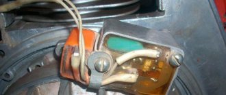
By purchasing the figure eight ignition components and playing with them, anyone can see that the dimensions and angles in the curtain drawing above are complete nonsense. They are absolutely unnecessary; a spark jumps out even if you rustle the sensor slot with the tip of a slotted screwdriver. In fact, when installing the BSZ you need to know only 2 things: 1) A spark jumps when the curtain halfway opens the sensor. 2) For the Ant motor, this moment should occur 3 mm before TDC. That's it, this information is enough to install the BSZ. After removing the impeller casing and examining possible mounting locations, it became clear that the sensor needed to be mounted from above. It won't interfere with air flow, and there's just enough room to mount the sensor to the crankcase, while the shutter can be attached to the flywheel. There are two options here: either attach the sensor without an adapter directly to the crankcase, in which case the curtain will have to be made in a Z-shape, or attach the sensor through an adapter, then the curtain will be a simple corner. I chose the first option. I drilled a couple of holes here:
And screwed the sensor into the standard holes
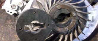
The curtain was made from an old mount for a three-inch drive. You can use an old case from any desktop, there is a good tin of just the right thickness, and there are ready-made neat grooves for adjusting the position of the curtain, if necessary. For mounting, I drilled a couple of holes in the flywheel and cut an M4 thread there (drill carefully so as not to drill through and damage the dynostarter winding). The depth of the hole is 7 millimeters. A long crank is convenient for cutting threads; in the photo there is a tin from which the curtain is cut.
How it all spins is clear from the video
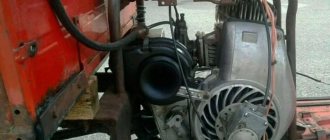
Final view - the central hole of the casing is closed with a standard rubber band, everything is beautiful
Source
Things went wrong
How to set the ignition on a VAZ 2106 yourself
Of course, the engine had to be half charged with spare parts made by no one. I suspect that the counterfeit goods with which I had to tinker for the last two days are being produced in some garage in Rostov-on-Don, or that the local workers are secretly making this nonsense at the factory. In any case, according to my information, traders bring this disgusting stuff from Rostov. The engine to which I have devoted the last two days has already been converted to a magneto. I don’t know why he bought it - I didn’t ask him for it. The old one was in good condition. Well, since I bought it, we’ll install it. It’s none of my business, of course, but I have an extremely negative attitude towards this kind of collective farm tuning.
How to set the ignition timing on an Ant scooter so that the engine runs well and starts
In order for any internal combustion engine to start and “work well” (and it is the Internal Combustion Engine installed on your scooter), you need to supply fuel to it and then ignite it at the right moment. Moreover, the engine does not work in only two cases:
You are interested in the second case. So:
The work of any internal combustion engine is to convert the reciprocating motion of the piston into the rotational motion of the shaft. This transformation occurs with the help of a crank mechanism (CSM). How this transformation occurs is known from the elementary school “Physics” course.
For “good” operation of the internal combustion engine, all the fuel must burn in the cylinder within a very specific time - while the shaft rotates at a certain angle. Like the picture below:
Help with ignition for engine from Murovya
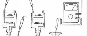
Contrary to popular myths and legends about its unreliability. Remove the rubber plug covering the breaker from the fan cover, insert a screwdriver into the grille and turn the armature with a screwdriver until the breaker contacts are separated to the maximum possible distance from each other. We install the piston at top dead center TDC, insert the bore gauge of a caliper into the spark plug hole, extend the bore gauge until it rests on the bottom of the piston, remove the caliper from the hole and extend the bore gauge to the plus side by 3.mm and fix the resulting value with a locking screw. Turn the engine a little clockwise, insert a caliper into the spark plug hole, turn the engine counterclockwise until the piston touches the bore gauge.
Electrical circuit of the motor scooter Ant 2M
The electrical wiring of the Ant 2 and 2M scooter (prototype – Tulitsa 2) is located at the bottom of the scooter. The cargo-passenger version is slightly different in appearance and electrical equipment. A more detailed power supply diagram of Ant 2M allows you to repair and tune the electrical equipment of the scooter.
Download the electrical diagram of the Ant 2M scooter:
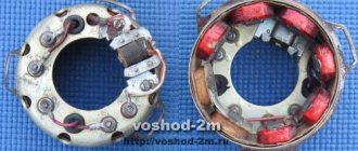
The dynostarter as a device is as far from complete perfection as our VAZ plant is from the premium segment. But if at least once a season you carry out competent maintenance of the collector unit, switching equipment, and battery, then with all its inherent shortcomings, the dyno starter can last a very, very long time, up to 30,000 km, or even more.
Why is the ignition adjusted?
Modern contactless ignition systems are reliable and accurate. As a result, car owners practically do not have to get into it in order to carry out adjustment work. The intervention is truly minimal. Moreover, if the settings are made, then only through a computer and special software.
The situation with traditional ignition systems, like that of the Ant scooter, is somewhat different. Here the setup is done manually. And you need to be consistent and attentive to do everything right.
If the ignition is set correctly, this will affect the performance of the scooter, as well as all its technical and operational characteristics.
The ignition is adjusted to ensure efficient engine operation. Sometimes owners of Ants can operate the equipment for a long time, even without paying attention to the fact that the ignition is knocked out.
The consequences of an incorrectly configured or broken ignition on a scooter are as follows:
- fuel consumption increases;
- unstable engine starting;
- problems when starting the engine;
- decrease in dynamics.
At some point, the Ant simply may not start. And no one needs the problem of increased fuel consumption.
Schematic diagram
As for the Ant's ignition system, you can upgrade it yourself. You can reduce the current passing through the contacts of the breaker using a transistor switch TK-102 (Fig. 1), which was used on the most common trucks in the past, ZIL-130, GAZ-53A, etc.
Rice. 1. Connection diagram of the transistor switch TK-102.
The use of a transistor switch makes it possible to use a higher-voltage B-114 ignition coil, which has a large secondary winding (41,500 turns). Since the voltage on the spark plug will increase from 17 to 25.30 kV, you can use a spark plug with a gap of up to 1.2 mm, which will save about 30% on gasoline.
System assembly and installation
The contacts in the breaker, the capacitor, the ignition bobbins and the armor wires, which are part of the previous ignition device, are probably eliminated. The switch should be installed in the glove compartment on the right, and the ignition coil directly under the tank. There are no gaps for fastening on the reel, which means it can be attached using a thick layer of adhesive tape. The standard bolt is also eliminated along with other parts.
In place of the bolt, install a pin of the specified size and put on a washer. Then, the rotor is tightened with a nut located at its end. The hall sensor is attached to the stator by any means. The basic rule when installing it is to set the optimal cross-sectional distance of the modulator and the ratio of the radius and line of symmetry.
When the hall sensor can be secured, we apply the modulator. It should fit into the hole made in the sensor. In most situations, there is a discrepancy between the sizes, so it is necessary to place washers on the stud. If you manage to maintain the required gap, it is recommended to install an engraver and tighten the modulator with a third-party nut.
Diagnostics
The first sign that something has burned out, shorted or broken in the dyno starter or relay regulator is when, out of the blue, right in the middle of the road, your battery charge control lamp comes on.
If this happens to you, then the first thing you need to do is inspect the wires going from the dyno starter to the relay regulator, check the fuse, remove the cover from the relay regulator and at least visually determine the integrity of its elements, remove the rotor and see what’s wrong with the brushes and collector and if nothing suspicious is found there, turn to a very competent electrician for help.
see also
Comments 10
If you still have a pressing question, send your email, I’ll send you a diagram for remaking the RR, very sensible, or look at the website motorscooter.ru
There is a dynastarter, and it has its own relay, with alternator-starter mode switching. It’s better, of course, to look for something native, but if you don’t have it, you can make something of your own if you have a specialist in electricity who understands. And the Lada transmissions, all these “tablets” and “chocolate bars” with old generators, work constantly. I installed the R-362 on a stationary diesel engine, as well as the R-356 on LUN generators, everything worked. Who is interested - www.reaa.ru/cgi-bin/yabb/YaBB.pl?num=1223834090.
You can’t put a relay from a Lada there, the generator design is not right.
VAZ CHOCOLATE, IF THE CURRENT IS 12 VOLTS, IF 6 VOLTS THEN THE CONTACT RELAY IS THE OLD LADY, WHICH IS ADJUSTABLE.
It’s better to look for something native, boo - they did it well before.
It won’t be a problem to find, you can hardly find analogues.
ready to sell this. write in PM
What happened to the original relay?
Is there a PP121 relay? It seems like the same thing should be on Tula... although I don’t know what’s easier to find.
Yes, in Tula it’s the same. order from the Internet or look on Avito in Russia, maybe there is something similar.
anthill scooter
I'll give my two cents.
First, decide what the scooter will be used for and how often it will be used. A 2000 year old is probably fine, so leave the working system alone, but put the battery at 12V/17H, go easy and start with the key. Tens of thousands of people must travel to disable a dynastarter.
As for the cam ignition, with all its shortcomings, it seems that the timing is not entirely accurate and so on. It has one big advantage - simplicity. Three details you can see and touch. Moreover, mechanics almost never surprise, which is not the case with electronics.
When problems arise, it is best to address them when they become available. Like any equipment, ants have their problems (with the dynastarter, clutch, carburetor, etc.). However, for many, this method has worked for decades with minimal care.
Well done admin Published March 25, 2011 - 16:51
The generator and starter in the same dynastar bottle remain in place, the switch is removed from the ant. An adapter is made between the shaft and the end of the crankshaft, the front panel is placed on the dynastarter housing, and a magnet is attached to it. Since the magnet will protrude, you will need to make a cutout in the hood. Were there diagrams and pictures in motorcycle magazines for 9? of the year. It was converted into a magnet and into a Voskhod generator. I liked the version with a generator better - in 20 years of operation, I changed the switch once, and that was all the maintenance.
Emil30_30 Published January 28, 2013 - 13:46
Members, I have a question for you. but in general it is possible to restore the entire enton mechanism, today I looked at the failure genes going to the coil and since I bought it second hand I would like to know if there is a relay that can be used instead of the usual one (pp-121 / 2903.3702) , since it is impossible to find it now, if you tell me I will be grateful.
Emil30_30 Published January 28, 2013 - 19:49
Home // How to install the ignition on a film anthill | | rel = 0; control = 0; showinfo = 0; iv_load_policy = 3;" frameborder =»0″ Fullscreen>
Sleeves on scooters. How to set up a magnet.
Subscribe to the new channel. https://m.youtube.com/channel/UCMds5tPNqtfKfhl-mOmQFTw.
Installing a magnet on an Ant motor, part 2
Installing a magnet on an Ant engine (part 2)
In each case, the reason may be completely different, so you must understand it deeply. Three holes with a diameter of 7 mm are drilled in the fan cover, which are necessary for attaching the magnetic adapter.
Like most Soviet equipment, this cargo scooter is reliable and easy to use, but a little rough around the edges.
Cleaning the collector
Take a small screwdriver and clean out the dirt between the slats. The collector must be cleaned very carefully so as not to scratch the lamellas.
After cleaning, blow the collector with compressed air, wash it with clean gasoline and wipe it dry with a rag. It is best to wash the collector with a brush: wet the brush in clean gasoline and wash it until the dirt is completely removed. When the gasoline has completely evaporated, take a piece of some lint-free cloth, moisten it a little in gasoline and carefully rub the collector with the maximum possible force until it is perfectly clean.
Contactless ignition Ant, Tula (FULL set of BSZ Muravey 2.5)
Topic of the section Homemade electronics, computer programs in the General Questions category; Hello everyone, I have an idea to install a spark ignition on my engine, I don’t have money to buy a specialized ignition, I want to make Forum Rules. Rules Advanced search. Forum General questions Homemade electronics, computer programs Electronic ignition circuit. Dear readers! Our articles talk about typical ways to resolve legal issues, but each case is unique. If you want to find out how to solve your particular problem, please use the online consultant form on the right or call the numbers provided on the website.
Source