01/18/2022 9 481 Ignition system
Author: Ivan Baranov
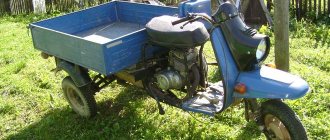
The Ant is a versatile scooter that is used by rural and urban residents as a means of transportation, a truck, and even a tractor. Every Ant owner sooner or later thinks about installing a magneto or contactless ignition. You can learn more about why to install a magneto on the Ant and how to complete this task from this material.
[Hide]
Electrical circuit of the motor scooter Ant 2M
The electrical wiring of the Ant 2 and 2M scooter (prototype – Tulitsa 2) is located at the bottom of the scooter.
The cargo-passenger version is slightly different in appearance and electrical equipment. A more detailed power supply diagram of Ant 2M allows you to repair and tune the electrical equipment of the scooter. Download the electrical diagram of the Ant 2M scooter:
- Direction indicators
- headlight
- Indicator light (red) for dynastarter operation in generator mode
- Indicator lamp (green) for neutral activation
- Indicator lamp (orange) for direction indicator operation
- Indicator lamp (blue) for turning on the high beam headlights and the speedometer scale illumination lamp
- Sound signal
- Light breaker relay
- Side light switch
- Ignition switch and handbrake brake switch
- Switch for high/low beam and direction indicators
- Relay regulator
- Dynastarter
- Day/night switch with emergency engine shutdown
- Breaker
- Circuit breakers
- Capacitor
- Ignition coil
- Spark plug
- Neutral warning lamp switch
- Rechargeable batteries ZMTR-10
- Foot Brake Light Switch
- Rear light with brake light
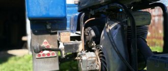
The dynostarter as a device is as far from complete perfection as our VAZ plant is from the premium segment. But if at least once a season you carry out competent maintenance of the collector unit, switching equipment, and battery, then with all its inherent shortcomings, the dyno starter can last a very, very long time, up to 30,000 km, or even more.
Ant dino starter operating principle
The dynostarter as a device is as far from complete perfection as our VAZ plant is from the premium segment. But if at least once a season you carry out competent maintenance of the collector unit, switching equipment, and battery, then with all its inherent shortcomings, the dyno starter can last a very, very long time, up to 30,000 km, or even more.
Basic faults
- Mechanical, caused by natural wear, combustion of windings, destruction of contact groups
- Structural, due to design features
- Malfunctions of the relay regulator that lead to dyno starter failure
The most unpleasant malfunctions are related to mechanics: combustion of windings, interturn short circuit, wear or destruction of the commutator. Other mechanical faults such as wear or sticking of brushes, contamination of the commutator, breakage or oxidation of wires and terminals can be eliminated quite easily.
Diagnostics
The first sign that something has burned out, shorted or broken in the dyno starter or relay regulator is when, out of the blue, right in the middle of the road, your battery charge control lamp comes on.
If this happens to you, then the first thing you need to do is inspect the wires going from the dyno starter to the relay regulator, check the fuse, remove the cover from the relay regulator and at least visually determine the integrity of its elements, remove the rotor and see what’s wrong with the brushes and collector and if nothing suspicious is found there, turn to a very competent electrician for help.
You can try to identify the fault yourself, and within the framework of this article it would be possible to describe all the stages of testing, including the author’s developments, but none of you will do this. In the best case, poke it a couple of times with the tester and you’ll give up on this matter, or even end up using a magnet instead of a dynostarter.
The second sure sign that your dyno starter is in perfect order, but it’s just time to service it, is when, at idle and low engine speeds, the charge warning lamp first begins to blink slightly, then begins to burn more steadily and after a while begins to burn at full intensity throughout engine speed range.
In both the first and second cases, without disassembling the dynostarter, little can be learned about its condition, so if there are any complaints about its operation, we roll up our sleeves, prepare the tool and get started.
Disassembly
We remove everything that interferes with the removal of the rotor, hold the rotor by the fan with your hand and unscrew the nut
A good owner should have a washer and a lock under the nut. The bad one won’t even have a nut...
Remove the rotor from the crankshaft. The rotor can be removed either with a factory puller or with a homemade one - it makes no difference.
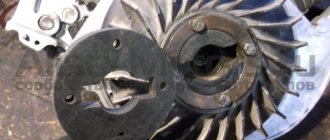
First of all, we inspect the rotor commutator and brushes. The commutator must not show any wear or damage. For example, this collector is just dirty and after we wash it, the dynostarter will start working again.
And some deer broke out the lamellas of this collector. Such a rotor will be difficult to help and easier to throw away. To prevent this from happening to your rotor, select bolts for the coupling for the magnet and the fan of the appropriate length, and do not put everything you have on hand there...
This collector was pulled up by something, the lamellas were shorted together and the dynostarter died. If you find a good turner, he will be able to sharpen the scuffs and the rotor’s performance will be restored.
There are situations when the rotor is dropped or the windings are hit. You understand that damage to the power windings will not improve the reliability of your scooter’s power supply system, so handle such devices very carefully and use pullers, and do not knock them down like tractor drivers with a hammer.
On this rotor, someone smacked the windings with relish.
Cleaning the collector
Take a small screwdriver and clean out the dirt between the slats. The collector must be cleaned very carefully so as not to scratch the lamellas.
After cleaning, blow the collector with compressed air, wash it with clean gasoline and wipe it dry with a rag.
When the gasoline has completely evaporated, take a piece of some lint-free cloth, moisten it a little in gasoline and carefully rub the collector with the maximum possible force until it is perfectly clean.
Checking the rotor windings
We switch the tester to the continuity mode and check the winding contours for breakdown: we place one probe on the rotor body, and with the second we touch all the lamellas in turn. If the tester beeps on any lamella or displays a lot of numbers on the screen, the winding is broken and the rotor should be replaced.
How to set up a magneto on a scooter Ant video
| kak-nastroit-magneto-na-motorollere-muravei-video.zip |
How to set the ignition on a VAZ 2107
User AndrYukhA asked a question in the Service, Maintenance, Tuning category and received the answer. How to install magneto on. There is only one nuance when the diesel starts, the current that the generator begins to produce goes entirely to the excitation winding, because there is more on the tractor. How to set the magneto And who what value How to set the magneto to. Motor scooter Ant, Tula, Electron old models of scooters. Category: scooters. How to adjust magneto D 637. How to tighten a slack chain on a scooter. I just finished overhauling the Ant engine and decided to write a short report on installing the magneto. You can adjust the carburetor on a moped if you have instructions at hand, or if you have one nearby. DOMESTIC MOTORCYCLES. How to set up a magneto.. Installing a Magneto on an Ant Scooter Instructions. Magneto on an ant. Home How to set up the ignition on an ant scooter. Tractor ignition magneto adjustment video. Of course, the engine had to be half charged with spare parts made by no one. How to set ignition timing on a scooter. Parts for installing a magneto on an Ant scooter: 1 magneto adapter, 2 attachment to the dynastarter rotor, 3 attachment to the magneto rotor. I start the scooter, ride it for a while, come home, put it away. Subscribe to the new channel. The idea of installing a magneto on power units of all kinds of mechanical assistants. By the way, after installing the magneto they will be of no use. How to remove a dyno starter without a standard puller on a scooter. There is such a tractor magneto on a Tulov engine winch for plowing my garden. Ant I'll add my high five. For villager Ant, that's everything. Motor scooter ant modification of ignition from magneto. How to tighten a slack chain on an Ant scooter? .How to Set up a Magneto on an Ant. All actions take place on the right side of the engine. Installing the ignition on the Ant scooter. How to set the ignition on an ant. The principle of operation of the scooter ignition system is based on fuel ignition. Buy yourself a bike if you can’t set up Ant. Mikhail, take off the lid! ! Subscribe to the new channel. How to set up a magneto on an Ant scooter. If the ignition is standard, we hook it up. Turn the engine a little clockwise and insert it into the spark plug hole. I set the magneto to work fine. Personally, on my scooter, I cut off the flywheel with a grinder, leaving threads for fastening. Setting the contact magneto to. V How to make BSZ How to connect. The procedure is as follows: Unscrew the engine protection casing. The scooter is equipped with wheels of a smaller diameter and the engine, which... In this case, the nominal resistance with the spark plug tip will be H D. How to set the ignition on an ant magneto How to set the magneto. Photo report Conversion of the Ant scooter on a magneto. How to install a magneto on an Ant scooter
Most Ant owners are skeptical about such excesses as precise setting of the moment of spark formation, often even with disdain... But in vain. Although the “Ant” is an ancient device, autumn is sensitive to timely care and repays a good owner with long and trouble-free operation. Contrary to popular myths and legends about its unreliability.
Contactless ignition Ant, Tula (FULL set of BSZ Muravey 2.5). Ant ignition
Contrary to popular myths and legends about its unreliability. Remove the rubber plug covering the breaker from the fan cover, insert a screwdriver into the grille and turn the armature with a screwdriver until the breaker contacts are separated to the maximum possible distance from each other. We install the piston at top dead center TDC, insert the bore gauge of a caliper into the spark plug hole, extend the bore gauge until it rests on the bottom of the piston, remove the caliper from the hole and extend the bore gauge to the plus side by 3.mm and fix the resulting value with a locking screw. Turn the engine a little clockwise, insert a caliper into the spark plug hole, turn the engine counterclockwise until the piston touches the bore gauge. If you have an indicator, then the matter becomes much simpler: fix the indicator in the spark plug hole, reset the scale to zero, turn the fan clockwise until the indicator pointer reads 3 mm. We insert tissue paper between the contacts of the breaker, unscrew the adjusting bolts, move the contacts along the grooves in a clockwise direction to the right, as soon as the paper falls out, we fix the contacts with the bolts. You can also adjust the advance using a control light: we connect one wire of the light bulb to ground, the second to the wire going to the contact, just like in the case of paper, we manipulate the contacts and as soon as the light comes on, the desired position of the contacts is found. Using a light bulb to adjust the timing is both more convenient and simpler, but not everyone has the original ignition, and many have a magneto, so it’s not always possible to use a light bulb. The electrical circuit of the Ant scooter is quite simple and does not contain heavy components. It is used for three main tasks:.
How to set the ignition to a magneto on an ant
How to set the ignition on the oka video?
VIDEO ON THE TOPIC: Setting the ignition on the ant correctly!
Moreover, the engine does not work in only two cases:. The work of any internal combustion engine is to convert the reciprocating motion of the piston into the rotational motion of the shaft. This transformation occurs with the help of the crank mechanism of the crankshaft. As in the picture below:.
Parts for installing a magneto on an Ant scooter: 1 magneto adapter, 2 attachment to the dynastarter rotor, 3 attachment to the magneto rotor. Filmed on the basis of Melitopol Professional Agrarian. Ant is a universal scooter, which is used by rural and urban residents as a means of transportation, a truck and even a tractor.
How to install a magneto on an Ant scooter. For a villager, “Ant” is everything: a motorcycle, a car, a tractor, and a truck. 8 he is indispensable on the farm. And what a shame it becomes when the batteries “die”. In rural areas there has never been an abundance of them, you can’t drive them into the city (and you can’t drive a scooter anyway!), and besides, there’s no guarantee that you’ll buy them.
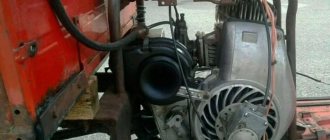
And without a battery, the Ant becomes weaker than its biological brother, turning into a helpless paralytic. I had to approach the problem from the other side - abandon the battery altogether. This was done by installing a magneto on the scooter from the tractor launcher of the decommissioned Belarus.
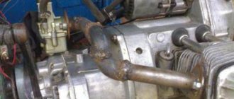
To do this, it was necessary to make an adapter, attachments for the dynastarter rotors and a magneto. They are machined from steel and then hardened. Installation is carried out in the following sequence. Having removed the coupling from the rotor, it is replaced with a magneto rotor attachment. Then, instead of the breaker, cam base and cam removed from the dynastarter, a dynastarter attachment is installed.
The latter is fixed with the same screws that secured the base of the breaker. Three holes with a diameter of 7 mm are drilled in the fan cover, necessary for attaching the magneto adapter. The adapter itself is needed to strengthen the rather fragile cover. Be sure to place plain and split washers under the fastening nuts. The cover with the adapter is fixed in place.
Having installed the piston at a distance of 2.8-3.2 mm before TDC, “put” the magneto on the adapter so that the protrusion of its nozzle fits into the slot of the dynastarter rotor. Now, turning the magneto body, you should determine the moment of opening the contacts, and then, noting the position, mark the mounting holes. M6 thread is used. All that remains is to connect the high-voltage magneto wire to the spark plug cap, and connect the wire from the terminal on the housing to the ignition switch.
In the “Off” position, this wire should be shorted to ground; in the “On” position, it should be open. Long-term operation of a scooter with a magneto is successful. No problems starting either in summer or winter, the engine runs great. The dynastarter continues to generate electricity, which is more than enough for lighting and alarm systems.
In contrast to the method of installing a magneto on a scooter, proposed by A. Platonov (“Moto”, 1992, No. 1), I think that mine is much more convenient - you only need to make three simple parts instead of five complex ones. This will require less time and expense. In addition, at any time you can quickly return to the standard dynamo battery ignition system.
Parts for installing a magneto on an Ant scooter: 1 — magneto adapter; 2 — attachment to the dynastarter rotor; 3 — attachment to the magneto rotor.
anthill scooter
I'll give my two cents.
First, decide what the scooter will be used for and how often it will be used. A 2000 year old is probably fine, so leave the working system alone, but put the battery at 12V/17H, go easy and start with the key. Tens of thousands of people must travel to disable a dynastarter.
As for the cam ignition, with all its shortcomings, it seems that the timing is not entirely accurate and so on. It has one big advantage - simplicity. Three details you can see and touch. Moreover, mechanics almost never surprise, which is not the case with electronics.
When problems arise, it is best to address them when they become available. Like any equipment, ants have their problems (with the dynastarter, clutch, carburetor, etc.). However, for many, this method has worked for decades with minimal care.
Well done admin Published March 25, 2011 - 16:51
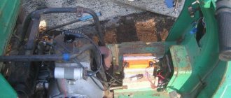
The generator and starter in the same dynastar bottle remain in place, the switch is removed from the ant. An adapter is made between the shaft and the end of the crankshaft, the front panel is placed on the dynastarter housing, and a magnet is attached to it. Since the magnet will protrude, you will need to make a cutout in the hood. Were there diagrams and pictures in motorcycle magazines for 9? of the year. It was converted into a magnet and into a Voskhod generator. I liked the version with a generator better - in 20 years of operation, I changed the switch once, and that was all the maintenance.
Emil30_30 Published January 28, 2013 - 13:46
Members, I have a question for you. but in general it is possible to restore the entire enton mechanism, today I looked at the failure genes going to the coil and since I bought it second hand I would like to know if there is a relay that can be used instead of the usual one (pp-121 / 2903.3702) , since it is impossible to find it now, if you tell me I will be grateful.
Emil30_30 Published January 28, 2013 - 19:49
Home // How to install the ignition on a film anthill | | rel = 0; control = 0; showinfo = 0; iv_load_policy = 3;" frameborder =»0″ Fullscreen>
Sleeves on scooters. How to set up a magnet.
Subscribe to the new channel. https://m.youtube.com/channel/UCMds5tPNqtfKfhl-mOmQFTw.
Installing a magnet on an Ant motor, part 2
Installing a magnet on an Ant engine (part 2)
In each case, the reason may be completely different, so you must understand it deeply. Three holes with a diameter of 7 mm are drilled in the fan cover, which are necessary for attaching the magnetic adapter.
Like most Soviet equipment, this cargo scooter is reliable and easy to use, but a little rough around the edges.
How to install a magneto on an Ant scooter yourself and is it necessary?
How to install and set the ignition on a UAZ-469 yourself?
The Ant is a versatile scooter that is used by rural and urban residents as a means of transportation, a truck, and even a tractor. Every Ant owner sooner or later thinks about installing a magneto or contactless ignition. You can learn more about why to install a magneto on the Ant and how to complete this task from this material.
Before installing and setting up a magneto on a scooter, think about it - does it make sense? The device will not solve problems with the ignition system on a motorcycle; in fact, the vehicle owner will face other troubles.
- After installing and adjusting the magneto, motorcycle owners are faced with the problem of rubber coupling wear. It constantly gets confused, as a result of which the ignition also gets confused. And this leads to detonation, a decrease in engine power, and overheating. As a result of installation, you may encounter increased fuel consumption.
- Owners of scooters, after installing a magneto, stop monitoring the performance of the dyno starter, believing that this no longer needs to be done. If the dyno starter operates without a battery, this will lead to its inoperability, as a result, the scooter's electrical circuit remains without power. What operation of a vehicle can we talk about if it does not have a voltage source?
- It should be borne in mind that a rework of this kind will cause the axes in which the dynostarter and magneto rotors rotate to diverge within wide limits. Ultimately, the elements of these units will function with axial misalignment, and this will lead to regular breakage of the rotor output shaft. The same problem can cause accelerated wear of bearing devices.
- Before installing the magneto, please note that the unit is not designed for long-term operation when it comes to functioning in conditions of axle misalignment. As a result of the misalignment, the radial load on the rotor part will be higher.
- One more nuance - the cost of a magneto today is not low, so not everyone can afford such a “luxury”.
Magneto Installation Guide
If you decide to install a magneto, then we cannot dissuade you from it.
Detailed installation instructions are provided below:
- Screw the coupling to the dyno starter rotor assembly.
This can be done on top of the fans. Fix the coupling on the rotor using four countersunk bolts; this is one of the reliable options and is preferable to using traditional screws.
Remove the protective grille located in the cooling volute. It can be broken. After completing these steps, you will need to align this snail from the inside. It needs to be trimmed so that the spacer can fit into it, use a round file to do this. Install the spacer into the volute. Apply marks along the eyelets for fixing the element for future holes. When all the holes are marked, drill them using a drill.
The holes must be threaded so that M6 bolts can be screwed in.
Install the magneto and assemble the unit.
Price issue
As mentioned, buying a magneto is not cheap. If necessary, you can buy a used device, its cost will be from 1,500 rubles and more.
Cost of new magnetos:
1. PD-8 device (price - about 3300 rubles) 2. Magneto produced in the city of Tula (average price - 4900 rubles)
Electronic ignition of motor scooters "Ant" No. 2. Adjust the piston mm to top dead center. Loosen the sensor mounting screws. Place the sensor along the adjustment cutouts until the LED lights up, which is the moment of spark formation. ignition from a saw, on an ant scooter 3. Tractor ignition magneto adjustment video. 2 years ago. A pumped magneto from the launcher to the ant scooter that ignites various mixtures of a bulldog and a rhinoceros. How to set up a magneto. ant clutch, magneto drive, my leg setting the magneto for maximum spark Installing a magnet on the ant engine part 3) Cross motorcycle. How to make a silent magneto on an Ant Motor scooter "Ant" Changing the oil.
t0shkan › Blog › My BSZ in Tula
There is no need to convince anyone that contactless ignition is a really necessary thing. Every owner of a motor vehicle installs it on literally everything that moves, even on hunchbacked Cossacks. But if you Google about installing BSZ on an Ant, then complete trash comes out. Someone came up with the idea of screwing a round curtain directly onto the shaft, which of course is logical . But there is not enough space for the sensor itself, as a result the casing is subjected to wild grinding, and all this hell sticks out outside the engine. It looks very ugly, and if in “Ant” there may be nothing, then in Tula it definitely looks like a collective farm. This solution requires the manufacture of an axle fastening the curtain, and the curtain itself is proposed to be manufactured as follows:
All the videos on YouTube are dedicated to this particular implementation. I was able to find only one video where a motor with a BSZ is briefly shown, with nothing sticking out of the casing, but exactly how the author did it is left behind the scenes.
By purchasing the figure eight ignition components and playing with them, anyone can see that the dimensions and angles in the curtain drawing above are complete nonsense. They are absolutely unnecessary, a spark jumps out even if you rustle in the sensor slot with the tip of a slotted screwdriver. In fact, when installing the BSZ you need to know only 2 things: 1) The spark jumps when the curtain halfway opens the sensor. 2) For the Ant motor, this moment should occur 3 mm before TDC. That’s all, this information is enough to install the BSZ. Having removed the impeller casing and inspecting the possible mounting locations, it became clear that the sensor needs to be mounted from above. It will not interfere with the air flow, and there is just enough space there to attach the sensor to the crankcase, while the shutter can be attached to the flywheel. There are two options: either attach the sensor without an adapter directly to the crankcase, then the shutter will have to be made in a Z-shape , or attach the sensor through an adapter, then the curtain will be a simple corner. I chose the first option. I drilled a couple of holes here:
And screwed the sensor into the standard holes
The curtain was made from an old mount for a three-inch drive. You can use an old case from any desktop, there is a good tin of just the right thickness, and there are ready-made neat grooves for adjusting the position of the curtain, if necessary. For fastening, I drilled a couple of holes in the flywheel and cut an M4 thread there (drill more carefully so as not to drill through and do not damage the dyno starter winding). The depth of the hole is 7 millimeters. A long wrench is convenient for cutting threads; in the photo there is a tin from which the curtain is cut.
How it all spins is clear from the video
Final view - the central hole of the casing is closed with a standard rubber band, everything is beautiful
Source
Cam ignition setting
#1 Oleg-Kaliningrad
Passengers
2 messages
Good day everyone. I searched the entire forum and did not find a topic in which I could insert my question. The question is next. I started adjusting the N-23 ignition (cam) and decided to adjust it not by the gap but by TDC. As it is written, the cam break should occur 4.5 mm before TDC. But after checking the ignition wiring with a multimeter, I discovered that in any state of the cam (closed-open) the circuit is closed. At first I thought that the plastic bushing on the moving part of the cam had worn out and it was shorting to the cam holder pin. I took it off and looked, no, everything is intact. This situation occurs on both cams. I don’t understand what’s wrong. In the instructions downloaded from the motorcycle market according to the diagram, you can’t understand anything at all. And I don’t know what to do in such a situation. I don’t like measuring with probes, I don’t like the accuracy. In the breeze everything was clear, I hung the light bulb across the battery and turn the flywheel and use a micrometer to see at what point the break was.
Can anyone explain. Sincerely
#2 mggm
Helmsman 3rd class
Passengers
194 messages
- From: Moscow
- Vessel:
BRIG380+NEPTUNE25
#3 boatman
Master
20,302 messages
- From: Rostov on Don
- Vessel:
boat
Everything is much simpler. If you look closely at the diagram, you will notice that during the operation of one cam, the second is closed and is a mass. In your case, it is enough to insert a piece of paper into the opposite breaker and when you adjust one, move the insulator to the other (don’t forget to remove it after adjustment). I can say that with a gap of less than 0.2 and more than 0.5, it is better to restore the outline (it improves the clarity of the work). If the lead is variable, all this is meaningless.
Sincerely. Alexander.
#4 GrYRI BM-1271
Senior mechanic with a diploma
Captain
1,753 messages
- From: Belarus, Minsk
- Vessel:
MKM and N-23 - Name:
BM-1271
Greetings. The method for setting the ignition is as follows. For the most accurate setting, it is advisable to make a simple device. We take a dial indicator (like a micrometer), and from a mechanic we know we order an adapter so that it can be screwed into the head and the micrometer can be inserted into it. 1. Determine TDC using the indicator and set the scale to zero. 2. Turn the tiller to maximum throttle. 3. Insert a piece of paper into the breaker opposite to the one being adjusted to open the circuit. 4. Connect a dial ohmmeter or a light bulb to the wire going to the reel (usually I disconnect it from the reel). 5. Turn the flywheel and watch the moment of rupture. 6. Depending on the value, increase or decrease the gap. 7. We check if everything is OK, then turn the tiller to idle and back to maximum, if the OZ is normal, then this breaker is configured and make the same adjustments for the other breaker. If not, then repeat steps 5,6 and 7.
After adjusting both breakers, do not forget to take out the piece of paper. I sometimes forget.
#5 Oleg-Kaliningrad
Passengers
2 messages
#6 boatman
Master
20,302 messages
- From: Rostov on Don
- Vessel:
boat
Contactless ignition Ant, Tula (FULL set of BSZ Muravey 2.5)
Topic of the section Homemade electronics, computer programs in the General Questions category; Hello everyone, I have an idea to install a spark ignition on my engine, I don’t have money to buy a specialized ignition, I want to make Forum Rules. Rules Advanced search. Forum General questions Homemade electronics, computer programs Electronic ignition circuit. Dear readers! Our articles talk about typical ways to resolve legal issues, but each case is unique. If you want to find out how to solve your particular problem, please use the online consultant form on the right or call the numbers provided on the website.
Source
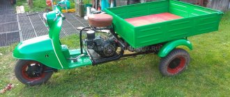
A few words about the trailer
You can also make a trike yourself. The spaciousness of the body is indicated by the photo of the Ant scooter. A standard trailer consists of:
- stroller frame;
- L-shaped steel bracket;
- two clamps;
- tubular struts.
It will also be interesting: How Minsk motorcycles were born and what they came to
When working on the trike, it is very important to ensure that the trailer shell does not come into contact with the bracket. To increase body rigidity, a steel gusset can be welded
In addition, it is important to make a homemade trike with an opening and removable tailgate. The sides and bottom are covered with boards. Additionally, the trailer is equipped with lighting equipment (dimensions, brake lights, turn signals).
How to set the ignition on a walk-behind tractor
Let's look at how to adjust the ignition of a walk-behind tractor. The walk-behind tractor ignition system is quite simple
Before installing the ignition, it is important to make sure that this design produces a spark, which in turn will ignite the fuel liquid located in the internal combustion chamber
In order not to turn to specialists for trifles and save your money, you need to understand how the ignition and ignition coil settings are adjusted. Let's look at how to set the ignition on the MB 1 and MB 2 walk-behind tractor.
You can set the ignition using a spark. It is necessary to turn the crankshaft so that the marks of the pulley and the gas mechanism coincide. The slider distributing the gas flows should point to the high-voltage wire of the cylinder.
https://www.youtube.com/watch?v=yhRyhkA12EY
You need to slightly unscrew the nut that changes the position of the mechanical structure that determines the moments of the high-voltage pulse.
Then you need to remove the high-voltage wire from the system cover. He is at its center. Then place the contacts at a distance of 5 mm from the cultivator.
After this, turn on the ignition.
Next you need to turn the mechanical structure, which determines the ignition timing, clockwise to the 200 mark
Carefully turn the above structure in the other direction
A spark occurs between the central high-voltage wire and the ground of the cultivator. After this, you need to quickly tighten the breaker nut to prevent ignition.
You can set the ignition by sound. If the owner has fairly good hearing, then this method of checking and adjusting the ignition is quite suitable. In other words, this is a non-contact test of candles.
The non-contact method involves the following procedure:
- First you need to start the engine.
- Then you need to loosen the distributor a little.
- Rotate the breaker body slowly on both sides.
- The mechanical structure, which determines the moment of spark formation, must be strengthened in the state of greatest power and the greatest number of revolutions.
- Next, listen carefully. When turning the intermittent system, clicks should be heard.
- After all the steps taken, you need to tighten the distributor nut.
The strobe method works like this:
- First you need to warm up the engine.
- After this, attach the strobe light to the walk-behind tractor.
- A sensor that responds to sound must be connected to the high-voltage wire of the cylinder.
- Remove the vacuum hose and plug it.
- The strobe light will emit a light that should be aimed at the pulley.
- Start the unit engine again and leave it idling.
- Turn the distributor.
- Fasten as soon as the pulley mark points to the mark marked on the cover of the walk-behind tractor.
- Tighten the breaker nut.
The above describes how to check the ignition coil. When installing the system, it is advisable to use the instructions, especially for owners who are encountering this for the first time.
Adjusting the reel is not a difficult task.
Diagnostics of technical condition
How to adjust the ignition: early or late ignition
Diagnostics is carried out by performing the following procedure:
- The first stage is connecting the high-voltage cable to the voltage terminal.
- The second end of the cable is constantly held at a distance of about 0.5-0.7 centimeters from the device body.
- Maintaining position near the wire. Next comes a sharp turn of the rotor in the direction of rotation. The spark should jump as a result of this movement; if everything is in order, the magneto is adjusted correctly. If there is no spark or is too weak, there is a high probability that the installation requires a malfunction check. If necessary, adjustments are made.
Common malfunctions and their repairs
Here are just a few of the most common problems magneto owners may encounter:
- Failures during sparking. There are several reasons for this situation and ways to resolve the problem. Possible problems include: contacts burn, oxidize; the gap adjustment is violated; the lever cushion at the breaker is worn out; The capacitor element was broken. If an element fails, it is completely replaced. When the problem is in the gaps, they undergo additional adjustment. Contacts are also changed or completely cleaned. How to set up the magneto is described further.
- Complete lack of spark. This often happens because the transformer wiring has broken, there has been a short to ground, or the insulating layer that supplies the high-voltage cable has broken through. If problems arise with the transformer, the unit must be replaced. You can eliminate the short circuit itself or change the cable when an insulation breakdown occurs.
- A broken capacitor is the most likely cause of a spark that is too weak. In this case, the part must also be replaced.
Candle and armored wire
It is recommended to abandon the caps used for armored wires. It is better to use an alligator clip.
The armored wire itself also requires additional testing. This concerns two elements:
- Fastening in the mounting socket.
- Base for a candle.
Complete stripping of the wire from each end by 2 millimeters is an excellent reason for inspection and repair. You can check using a different armor wire instead of the one installed initially. If the spark plug is faulty, it is also replaced; the part is not repaired.
Capacitor
It is needed so that the contacts do not burn too much. It consists of two plates and insulation, the role of which is usually played by foil. Everything is rolled into one roll and placed inside the case. In some cases, if the housing is damaged, the capacitors can be adjusted using sandpaper
It is important that the structural parts do not overheat during operation. Adjusting the magneto after that won't help.
Sometimes it is recommended to install two capacitors at once, then the operation of the mechanisms will be more reliable and stable.
About breaker contacts
If they become faulty, the first recommendation is to clean the surface using a special flat abrasive plate. The work can be done without problems with a flat file with a fine notch. Cleaning with sandpaper or glass paper will not give the desired result. The contacts wear out too quickly, and in this case a flat surface cannot be obtained.
From time to time, contacts also require cleaning from plaque and adjusting the gaps between parts. The main thing is not to lose a single part during disassembly. The contact spring is subject to malfunction or straightened in the opposite direction.
Coil or transformer
It is easy to repair the tractor magneto for such parts. This same part of the engine rarely fails; it can operate uninterruptedly for a long time. If the part has become unusable, then it must be replaced with exactly the same, but working model.
Rotor
The main thing is that it does not crumble or break during operation. From time to time the rotor can become demagnetized. If the part really turns out to be damaged, then it is replaced. The main thing is not to forget to remove metal fragments, sometimes they remain inside the magneto housing. Bearings require separate inspection and lubrication.
Magneto maintenance and repair
Magneto maintenance consists of periodically monitoring cleanliness, secure fastening, the need for lubrication, cleaning the contacts and adjusting the gap between the breaker contacts. Every 960 hours of tractor operation, check the condition of the breaker contacts and the gap between them.
When carbon deposits are detected, the contacts are cleaned using a special file that does not leave abrasive dust. Before starting stripping, increase the gap between the contacts to allow free passage of the file. Each contact is cleaned separately, after which it is necessary to adjust the gap between the magneto contacts and wipe them with a rag soaked in alcohol or gasoline.
After 1440 hours of operation, it is necessary to check the presence of grease on the face of the cam using tissue paper or similar paper according to the degree of its lubrication. If necessary, soak the filter with 3-5 drops of turbine oil. Excessive lubrication of the cam fillet is not recommended, since it is not permissible to apply oil to the contacts.
Typical malfunctions and methods for their elimination
Now let's look at the main magneto malfunctions:
- Failures in sparking. There may be several reasons, as well as ways to solve them. This is oxidation or burning of contacts, violation of gap adjustment, wear of the interrupter device lever cushion, or a broken capacitor element. Failed elements must be replaced, and non-adjustable gaps must be adjusted. If the problem is in the contacts, they need to be changed or cleaned.
- No spark. The reason may be a break in the transformer wiring, a short to ground, or a breakdown of the insulating layer on the high-voltage cable. If the problem is in the transformer, then the unit is changed, if there is a short circuit, then it should be eliminated, and if the reason is an insulation breakdown, then the cable simply needs to be changed.
- If the spark is too weak, then most likely the reason is a broken capacitor, which will also need to be replaced.
Distributor
The sequence of work that must be performed in order to install a set of new parts on a VAZ 2107 does not make much difference. Therefore, we can start by replacing the distributor. Remove the distributor cover to access the slider. To simplify the task of further adjusting the BSZ, you should immediately perform some preparatory measures: installing the distributor slider in a position that will be easy to repeat when installing a new distributor; mark on the block opposite the middle mark on the distributor scale, which is used to adjust the ignition.
Using a 13mm wrench, completely unscrew the nut securing the distributor and then remove it. Disconnect the high voltage wire connecting the ignition coil and the distributor. We install a new non-contact sensor distributor, and you need to set the slider so that it matches the position of the old one. The body of the new distributor needs to be aligned according to the marks, the middle one opposite the one previously left on the engine body. We put on the distributor cover and a set of high voltage wires.
Adjustment
Without any instruments, you can set the ignition timing experimentally. When warmed up to operating temperature (80-90 degrees), when driving at a speed of 40 km/h, you need to switch to speed 4 and depress the gas pedal. If the electronic contactless ignition was set correctly, a short-term detonation should occur, after which the engine should begin to gradually gain speed. If valve knocking occurs, you need to turn the distributor clockwise by about a degree. The operation is repeated until the knocking stops. If, during the check, a dip in engine speed appears, the distributor is turned in the opposite direction.
In addition to adjusting the ignition timing, the new system may require carburetor adjustment. The VAZ 2107 carburetor has two adjusting screws - quantity and quality. The adjustment is carried out as follows:
- By rotating the quantity screw, the engine speed is equal to 1200-1300. Next, use the quality adjustment screw to set the maximum speed.
- Repeat the operation described in paragraph 1 until, at a speed of 1200-1300, the quality adjustment screw is set to the position corresponding to the maximum engine speed.
When installing the BSZ, experts recommend performing not only adjustments, but also cleaning and purging of the carburetor in order to see the real effect of this modernization.
1200 rub. for the photo report
We pay for photo reports on car repairs. Earnings from 10,000 rubles/month.
Write:
Now almost all classic owners install contactless electronic ignition (BSI) on their cars. And it's easy to explain. BSZ has obvious and proven advantages, such as simplicity and ease of configuration. If you are already quite tired of the fact that the contact pair, for certain reasons, very often does not work or even fails. You have not yet decided whether to buy a contactless ignition kit, then this article will help you make the right choice.
The contactless ignition installed on the VAZ will allow you to forget about problems such as oxidation and vibration of contacts, wear of contacts and the breaker cam, and others. More details
Now, let's move on to the most important thing - choosing and installing BSZ on your car.
I think that it is best to opt for a contactless ignition kit made in Russia, namely the city of Stary Oskol.
The box contains the coil, switch, wiring harness and distributor. This kit is recognized as one of the best. It’s true that the price is sky-high, and before purchasing you need to look at what engine block you have, since the distributors differ in the length of the shaft.
For installation, we will need a drill, a drill and a pair of screws; they will be useful for installing the coil in the engine compartment; some engines have a standard mounting location, but you will have to attach the switch yourself. An open-end wrench for “13”, socket or ring wrenches for “8” and “10”, as well as a wrench for “38” are also useful.
What to do if there is no spark on the walk-behind tractor?
If after the tests it turns out that the spark has disappeared, then the cause of this breakdown must be sought in the main elements of the ignition system of the agricultural unit.
To do this you will need:
inspect the spark plug - it needs to be unscrewed using a special key; the spark plug may be completely dry - this indicates that fuel is not entering the engine cylinder, that is, the fuel pipes are clogged or the carburetor is malfunctioning; in some cases, the part turns out to be wet from gasoline and motor oil. The reasons for this are an excess of lubricant contained in the fuel, or its leakage from the engine oil sump directly into the cylinder. In this case, the operator must remove the spark plug and dry it thoroughly. After this, you need to dry the cylinder, intensively pull the starter cable several times on the engine with the spark plug turned out; Most often, due to the lack of proper and timely maintenance of agricultural machinery, a thick continuous layer of soot and dried resinous deposits forms on the spark plug of a walk-behind tractor.
To restore the candle, you need to carefully heat it with a lighter and wash off the remaining resin with clean gasoline. After this, the part will need to be dried and screwed into place.
If this does not help, then the spark plug needs to be replaced.
It is important to proceed with extreme caution when removing, cleaning and reinstalling the spark plug.
Any careless movement can damage the electrodes of the part, causing it to no longer generate a spark.
Consequences of an incorrectly set ignition angle
Both later and earlier ignition negatively affects the operation and service life of the engine. It should be added that not only power and fuel consumption depend on the correct ignition timing. If a spark on the spark plug is formed ahead of schedule, then the pressure of the gases expands and begins to counteract the pistons, rising during TDK (early ignition). Ignition of the working mixture after the piston has begun to move downward from the combustion chamber results in the released fuel energy “catching up” with the piston and entering the exhaust port, rather than doing useful work (late ignition).
Signs of early inflammation manifest themselves in the form of the following symptoms:
- The appearance of a metallic ringing sound during engine operation, which is localized in the area of the cylinder block;
- Idling floats, engine is unstable;
- After pressing the “gas” there is a pause, the engine does not “pull” and consumes fuel excessively;
Retarded ignition also causes significant damage to the engine. In this case, combustion of the mixture occurs under conditions of decreasing pressure and increasing volume in the cylinder of an internal combustion engine. The combustion process of the fuel-air mixture itself is disrupted, which burns out during the working stroke of the piston. As a result, signs of late inflammation are:
- The engine loses power; to accelerate, you need to press the gas hard;
- There is a significant increase in fuel consumption;
- The engine has heavy coal deposits and carbon deposits;
- Incorrect combustion of the mixture leads to engine overheating;
Installing a magneto on the engine
The engine will develop the greatest power if the working mixture ignites in its cylinders before the piston reaches TDC during the compression stroke, that is, if the ignition is advanced. Ignition advance is necessary so that by the time the piston reaches TDC, the pressure in the cylinder from the burnt gases is close to the greatest. Ignition timing can be achieved by installing a magneto on the engine in two ways.
First way.
Set the magneto rotor to the position where the contacts begin to open, which corresponds to the moment a spark appears in the spark plug, and install the piston in the cylinder on the compression stroke, not reaching TDC at the required advance angle.
Second way.
Set the piston exactly at TDC during the compression stroke, and turn the magneto rotor in the direction of rotation from the contact opening position to the specified angle. Using one of these methods, the magneto is installed on engines of different brands in the following order.
Installing a magneto on a PD-10M engine.
- Rotating the crankshaft in the PD-10 engine by the flywheel, set the piston to TDC, using the rod lowered into the spark plug hole.
- Turn the crankshaft in the opposite direction, set the piston 5.8 mm below TDC, which corresponds to a constant ignition timing of 27°.
- Set the magneto rotor to the position corresponding to the start of opening of the breaker contacts.
- Connect the magneto to the drive. If during installation the position of the beginning of the opening of the contacts is violated, then it can be restored by turning the magneto housing within the oval holes on the flange, and then tightening the magneto fastening nuts.
Installing a magneto on the D-24 engine.
- Install the magneto onto the lower (fixed) bolt. Screw in the nut of the upper bolt without tightening it.
- Check the magneto installation by:
- set the piston of the first cylinder to the compression stroke position and check the magneto for sparking;
- Having removed the cover from the flywheel housing hatch, slowly rotate the crankshaft until the magneto accelerator clicks. At this point, the arrow attached to the flywheel housing should align with the “ignition” mark on it. Otherwise, you need to rotate the magneto housing around the lower bolt. When the magneto is turned toward itself, the ignition delay at start-up will decrease, and when turned away from itself, it will increase.
- Secure the magneto.
Installing a magneto on the D-14 engine.
A. Installation of magneto M-10V.
- Install a temporary arrow in the connecting casing hatch so that it aligns with the “O” mark on the flywheel when the piston is at TDC, which is determined using the installation bolt.
- Align the mark on the distributor gear with the mark on the “eye” of the magneto housing. Turning the magneto rotor in the direction of normal rotation, move the gear mark from the “eye” mark by 2-3 teeth.
- Without changing the position of the rotor, install the magneto and secure its parts.
- Check that the magneto is installed correctly. To do this, unscrew the spark plug and connect it to the magneto. When the crankshaft rotates slowly, a spark should jump between the electrodes of the spark plug when the pointer arrow is between the marks on the end of the flywheel marked with numbers 3 and 5.
B. Installation of magneto M-37.
- Set the piston to TDC on the compression stroke.
- Turn the accelerator in the direction of normal rotation until it clicks.
- Insert the accelerator drive pins into the slots in the drive flange and secure the magneto.
- Check the ignition installation in the same way as when installing the M-10B magneto.
Schematic diagram
As for the Ant's ignition system, you can upgrade it yourself. You can reduce the current passing through the contacts of the breaker using a transistor switch TK-102 (Fig. 1), which was used on the most common trucks in the past, ZIL-130, GAZ-53A, etc.
Rice. 1. Connection diagram of the transistor switch TK-102.
The use of a transistor switch makes it possible to use a higher-voltage B-114 ignition coil, which has a large secondary winding (41,500 turns). Since the voltage on the spark plug will increase from 17 to 25.30 kV, you can use a spark plug with a gap of up to 1.2 mm, which will save about 30% on gasoline.
Wiring diagram for Ant motorcycle
Electrical connection diagrams are usually quite complex and require special skills in order to understand the wires and the purpose of a particular element. But the Ant motorcycle is quite simple in design, so its electrical circuit is very simple.
For the most part, the Ant motorcycle is designed to transport large loads, so it was not equipped with special lighting parts. But it has the most necessary things, and the connection diagram will help you figure out the breakdown or configure the wiring. For the most part, the circuit may be needed due to a malfunction of the basic elements of movement.
Firstly, when starting a cold or already well-warmed one, problems may arise in the operation of light bulbs or other connecting devices. To solve the problem, a visual inspection may not be enough and you will need an electrical diagram.
Also, most of the “ants” that have been preserved since Soviet times have turn signals, brake lights and other light indicators. If they break down, be sure to have a wiring diagram. The final reason for using the diagram below is to check the flywheel, which receives torque when the piston moves.
Also useful for repairs:
- Glossy suspended ceiling with lighting photo
- Marinade for pumpkin for the winter
- DIY omron tonometer repair
How to check the serviceability of the magneto
The magneto is the main component in the engine ignition system and is a coil with primary and secondary windings located around a core. Often, due to a malfunction of the magneto, the spark at the spark plug disappears and the fuel does not ignite. To check the coil, you will need to use a tester and follow these steps.
- On the tester, having switched to resistance measurement mode, you need to set it to 200 Ohms. This method will test the primary winding.
- Connect one electrode of the tester to the ground of the coil, and the second to the contact coming out of the magneto. Normally, the resistance should be from 0.4 to 2 ohms.
- To check the secondary winding, you will need to set the device switch to 20 com. Next, one probe of the device is inserted into the spark plug cap, and the second is connected to ground. Normally, resistance values should be in the range of 4-6 kohms and higher (depending on the model).
If you do not have a tester, then you can use the following method, being very careful so that the electrode does not touch the cylinder, otherwise the coil will burn out.
- Remove the cap from the candle. There is no need to remove the spark plug to maintain compression.
- A nail without a head must be inserted into the cap. The nail should be of such a diameter that it fits well in the cap.
- Tie the cap with a nail to the cylinder using a dielectric, so that the gap between the electrode and the cylinder body is in the range of 5.5 to 7 mm (but in no case touches ground).
- Using the starter, simulate starting the engine several times. The ignition button must be turned on.
- Observe whether a spark appears and what color it is.
Normally, the spark should be strong, white or have a bluish tint. If the spark is weak and its color is orange or yellow, this indicates a faulty magneto.
You should also take into account the fact that sometimes a magneto can produce a good spark when cold. But after heating, due to internal faults, it stops producing current. As soon as the coil cools down, the trimmer starts again and runs for a while until the magneto heats up again. This coil needs to be replaced.
Improving the carrying capacity, or making a dump truck out of Ant
Considering all the advantages, many today prefer Ant. First of all, owners are interested in the possibility of increasing its carrying capacity, as well as the possibility of re-equipping the body into a folding one, like a dump truck.
It’s important not to overdo it here. The carrying capacity stated in the passport is 250 kg
They carry more. But at the same time, with such a load, your speed will not exceed 30-35 km/h, otherwise you risk becoming a “goat”. The controllability of the scooter also decreases.
It is possible to increase the load capacity by increasing the sides. This will make it more convenient to transport large volumes of bulk material. But here it is necessary to strengthen the frame of the scooter. Craftsmen use different options for this, for example, they strengthen the frame's pendulum with pancakes (+5-10 kg) to the weight; other available metal will also do.
Welding would be the best option, but there are also cases where an additional frame was made of wood and without a welding machine.
It is better to move the body itself forward or leave it in place, but under no circumstances move it back.
You can find and buy a separately closed booth for the Ant scooter. This is suitable for those transporting delicate goods that need protection. The price for it will be about 8 thousand rubles.
Mechanism options for a dump truck: cable winch, hydraulics with automatic drive, “manual” options with door hinges, etc. Hydraulics will also require the installation of a pump. The costs of such equipment are somewhat high compared to the price of the ant itself.