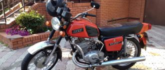
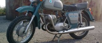
Izhevsk motorcycle can certainly be considered one of the most elegant and reliable. Being very light and compact, this motorcycle is capable of carrying incredibly large loads. Thus, the IZ Jupiter 5 engine is capable of withstanding a load of 500 kg !
This is an excellent result. The motorcycle itself looks sporty. Classic minimalism of the Soviet period was intended more for the youth of that time, but was popular among all age groups.
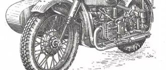
IZH has the ability to install a cargo module or stroller, which is very convenient when transporting passengers or massive cargo. At the same time, it has excellent cross-country ability on any soil or road surface. However, traction is significantly reduced in wet weather, and stability issues may arise in muddy conditions.
The unit is very unpretentious to weather conditions. In severe frost, down to -30 degrees, starting the engine is not difficult. Even in extreme heat, there are no problems with overheating.
The characteristics of the IZH Jupiter 5 engine were quite good for Soviet times. The two-cylinder engine produced about 25 horsepower, allowing the bike to accelerate to 120 km/h. For comparison, Ural and Dnepr motorcycles had an average maximum speed of approximately 110 km/h . However, like any Soviet bike, problems arise with reliability. Frequent engine repairs of the IZH Jupiter 5 are part of the operation of the motorcycle.
How to disassemble the IZ Jupiter 5 engine
[sc:ads3]
So, disassembling the IZ Jupiter 5 engine includes the following steps:
- First you need to wash the hard-working heart of the motorcycle. You need to rinse it as thoroughly as possible, since dirt should not end up inside the engine, otherwise most of the work will most likely go down the drain.
- Take a piece of paper with a pen to write down the location of the parts and the order in which they are installed as you work. All bolts, studs and dowels have their place and order of tightening. Therefore, there is no need to scatter them in different directions, but it is better to fold them as they are disassembled.
- It is necessary to tighten the exhaust tube. Don't throw it away, tie it to something strong.
- After unscrewing the 4 nuts, remove the cylinder covers and the cylinders themselves, being careful not to damage the gaskets. If the gaskets are damaged, then the pressure inside the engine will be compromised.
- Now you need to tighten the tube on the chain cover. We knock out the stud on the front of the engine halfway. It is important not to bend it, otherwise you will have to look for a new one.
- Unscrew the nuts and remove the bolt securing the engine at the rear. It is better to lay out the parts in groups so as not to lose or mix them up.
- We unscrew the seven bolts securing the pan, remove the flywheel plate and gasket, and fix the engine. It is better to fix the engine on a workbench; if you don’t have one, then a massive table will do.
- Using a socket wrench and a long, strong pry bar, loosen the bolt holding the take-out flywheel together. Be careful not to break the thread on the cap - this will make the task much more difficult.
- Disconnect the crankcase halves. We don’t put them away, they will come in handy soon.
- Remove the take-out flywheel and veneer.
- We take out the middle and front shafts, the follower shaft, and remember the installation location of the adjusting washers. It is important to remember their exact location, otherwise parts will not fit together later.
- We unscrew the pins securing the crank chamber covers and remove the covers with rings. The pins are quite fragile, if you break them while unscrewing them, it will be difficult to get them out.
- We remove the crankshafts from the halves of the pallet.
- Pull out the bearings of the crankcase half. Don't bend the crankcase or your oil will be used up very quickly.
- Unscrew the screws and the race with the crankshaft oil seal.
- We take out the installation rings and knock out the seals.
- We knock out the bearing of the right half of the pan.
- Disassembly of the IZH Jupiter engine is completed.
Now that you have looked at all the parts from the inside and found the problem, we replace the broken part. The easiest way is to look on the Internet at a spare parts sales site. You can also find it at a regular city market (flea market). Before assembling the IZH Jupiter 5 engine, carefully inspect its surface for chips, cracks, and wear again.
After you have thrown out the broken part and stuck a new, shiny one in its place, you need to return everything to the way it was. Assembling the IZ Jupiter 5 engine is a little more difficult than disassembling it. Everything is put together in reverse order.
As you can see, there is nothing complicated about this. It's another matter if you want to add a couple of horses to your pet. Then you will have to sweat a little, because tuning the IZ Jupiter engine will require a little patience from you.
Engine diagnostics and repair
It is sometimes impossible to find the cause of a breakdown after one visual inspection. In some cases, complete disassembly of the IZH Jupiter 5 engine is necessary. But if you find out the reason, you can quickly solve the problem yourself. Here are examples of main faults and repair recommendations:
- If your kickstarter turns on the crankshaft, you must:
- Tighten the fasteners more tightly, and in case of severe damage, replace the kickstarter shaft and lever. This usually happens after the IZ Jupiter 5 engine has been boosted.
- If the oil is selected incorrectly, especially if it is very viscous in winter, it is necessary to select a more correct temperature regime.
- If the trigger spring is weakened, it must be replaced.
- If no fuel gets into the carburetor, you should clean it in a solvent, and also blow out the channels and fuel supply hose with pressurized air.
- If there is no spark in the combustion chamber, replace the spark plug or clean it.
- When the throttle valve sticks, it is necessary to adjust its drive and clean the carburetor.
- Fuel supply system. The fuel mixture may be oversaturated with air. The solution to this problem is to replace the air filters and install new gaskets.
- Is the capacitor OK? If strong sparking occurs between the contacts, the capacitor must be replaced.
- Severe wear or burning of the spark plug. In most cases, it is the spark plugs that cause poor starting and uneven engine operation.
- The drainage hole of the fuel drum should be cleaned.
- There are cases where the carburetor needle falls out. It needs to be inserted into place and adjusted.
- Cleaning and purging of carburetor channels and jets.
- Adjusting the carburetor to supply gasoline for a combustible mixture. When the quantity is large, popping noises occur in the muffler , because the mixture hits the hot metal walls and burns out there.
- If the fuel manifold drive becomes stuck, the needle must be returned to its standard position.
- In case of low cylinder compression, it is necessary to remove all carbon deposits from the piston and clean the piston rings. And in case of severe damage, completely replace the piston along with the cylinder. To prevent malfunctions, you should use only high-quality fuel and oil from trusted manufacturers.
- Ignition adjustment. With early ignition, you can hear the engine knocking, and with late ignition, popping noises in the exhaust pipe.
These are the main problems that may occur during operation. How to disassemble the IZ Jupiter 5 engine is written in detail in the maintenance book issued upon purchase. Everything stated in it is written in clear text, with diagrams and detailed instructions. Not only the repair of a Soviet unit is within the power of any owner.
There are many questions about how to assemble the IZH Jupiter 5 engine yourself, modifying it. For example, installing a more reliable carburetor or a more stylish and loud muffler can be done quickly enough without significant financial investments.
Tuning an IZH Jupiter engine with your own hands is possible if you have enough time and enthusiasm. You just need to be persistent.
The motorcycle has a favorable ratio of cost, build quality and maintenance requirements. An ideal option for people with a small budget and those who want to get universal equipment. However, frequent breakdowns will take a lot of time. It's worth being prepared for this, since some bikes can be 40-50 years old.
Instructions for assembling and disassembling the IZH Jupiter 5 engine
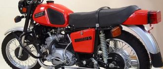
First, you need to understand the features of the motorcycle. IZH Jupiter-5 is a vehicle designed for road travel with different surfaces. You can attach a stroller and a cargo module. The appearance of Jupiter-5 is distinguished by the strict classics inherent in the Soviet era, but at the same time it has its own individuality.
The demand for this model lies in the small dimensions of the motorcycle, as well as decent power for that time. The engine of this motorcycle has two cylinders and two strokes. The cylinders are arranged in-line. The maximum developed power reaches 25 horses, which is 3 more than the single-cylinder IL Planet-5. This engine allows the motorcycle to move at a maximum speed of 120 km/h, while it has low fuel consumption.
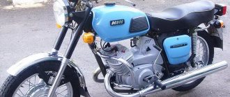
What sets the bike apart is its ability to operate even in harsh climatic conditions. It is not at all whimsical: it can start both in -30 degrees and in heat over +40, and is not afraid of rain and dirt. However, moving on the ground during rain is not as easy as we would like. Unlike the “Planet”, during the trip you don’t feel any unnecessary vibration , the movement is dynamic and very smooth.
The Izhevsk Machine-Building Plant began producing IZH Jupiter-5 in 1985, so spare parts are always available. However, the quality leaves much to be desired, which is why parts wear out quickly and the motorcycle requires fairly regular repairs. Sometimes, to find the cause of a breakdown, you have to disassemble half of what you didn’t even know about. Fortunately, in IZh everything is quite simple and the repair can be done at home. Repairing the IZ Jupiter 5 engine is not a difficult task, but if you are going to ride this motorcycle often, then you should not neglect to do the work correctly.
The main problems of Jupiter-5 include the current shock absorbers and cylinders, which alternately refuse to operate the engine. If you have encountered similar problems, then this article may help you in solving one of the annoying problems.
Write a review
Register by leaving product reviews and you can earn bonus points!
Your review: Attention: HTML is not supported! Use plain text.
Rating: Bad Good
Enter the code shown in the picture:
Typically, the problem of replacing a connecting rod in the crankshaft is faced by owners of two-stroke equipment, these are motorcycles Minsk, Voskhod, IZH, Krosoviki, snowmobiles, scooters and mopeds. The crankshaft caught fire, the question arises, how to repair the crankshaft of a motorcycle, the answer has been found, the first is to buy a new crankshaft, the second is to replace the connecting rod, pin and needle bearing (separator) for a broken crankshaft).
A new crankshaft is, of course, easier to buy, but the price of a crankshaft is five times higher than the price of a connecting rod with a pin and a needle bearing. Here the problem immediately arises of how to disassemble the crankshaft yourself at home, then compress it and eliminate the knock. Of course, to eliminate runout, any master will look for a lathe, but this is a useless problem. There is a way I came up with to eliminate crankshaft runout at home without a lathe.
If you decide to replace the connecting rod in the crankshaft of a motorcycle yourself, then this article is for you. Why pay extra for a new crankshaft when replacing a connecting rod will turn a broken crankshaft into a new one.
Just don’t try to heat the crankshaft, everything is done cold.
Electrical equipment IZH Planet 5
Wiring for IZH Planet 5 includes:
- generator;
- battery;
- ignition system;
- headlights;
- control devices;
- switching elements.
Video: review of IZH Planet 5 wiring
Taken by user Agronom.
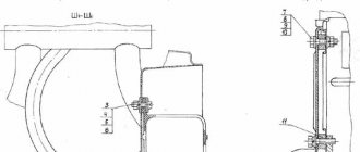
Generator
IZ Planet 5 generator design:
- voltage regulator with rectifier BPV-14-10 - 1;
- rotor - 2;
- stator with windings - 3;
- current collector brushes - 4;
- ignition system cam (battery) - 5;
- ignition system contact unit - 6.
The generator converts the mechanical energy of a gasoline engine into electrical energy, which charges the battery. Alternating current is generated by 3 windings and fed to a rectifier, which converts it into direct current. An additional coil is used as an exciter.
Photo gallery: IZH Planet 5 generator and its design
Battery
To supply all components, a low-power energy storage device of 12 volts is required, since IZH Planet 5 does not have a starter. The purpose of a lead-acid battery is only to supply voltage to the ignition system and the excitation winding of the generator during startup.
Ignition system
In IZH Planet 5, the ignition coil converts low-voltage voltage into high-voltage and transmits it to the spark plug. That, in turn, is responsible for the spark that detonates the fuel. To ensure that detonation occurs only in the desired piston position, there is an ignition chopper.
From the factory, this model is equipped with a classic ignition system, which requires periodic cleaning of the breaker contacts and adjusting the gap between them.
Installing a contactless SG on a motorcycle gives:
- timely powerful sparking;
- reduction of vibration levels;
- reduction in fuel consumption.
Control devices
The following control devices are installed on the motorcycle:
- tachometer, on which there are indicator lights for the headlights and turns;
- speedometer showing total and daily mileage;
- power engine temperature indicator;
- voltmeter.
Headlight and dashboard lamps
Conventional incandescent lamps are installed as lighting equipment and to illuminate the dashboard. Switching elements are responsible for supplying electricity from the battery to the lamps.
The headlight circuit includes lamps:
- headlight (35 watt);
- parking light headlights (4 W);
- control - blue light (2 watts);
- rear brake light (15 W).
Switching elements
Switching elements are various types of switches that close or open an electrical circuit. They can be activated using keys on the dashboard (for example, turn signals) or by sensors.
In IZH Planet 5, the switching elements include:
- turn switches;
- signal key;
- switches for low/high beam headlights;
- neutral sensor;
- egnition lock;
- foot and hand brake sensors.
Tools
Tools you will need:
- Drill or screwdriver
- Metal drill 4 - 5 mm
- Flat file
- Technical hair dryer
- Mandrels. Plumbing fittings can be used as mandrels
- Powerful flat head screwdriver
- Open-end or socket wrench 14
- Clamp
- Hammer or mallet
- Oil can or syringe
- Sealant
Required Parts
In order for the ignition system to work correctly, a number of auxiliary parts are required. They are listed below:
- Switch for BSZ VAZ cars. You should not choose exclusively from the low price segment. The Astro switch has a lot of positive reviews;
- Hall Sensor. The best option for Jupiter 5 is a similar manufacturer VAZ. By purchasing it in branded packaging, you protect yourself from counterfeits;
- Ignition coil with two terminals. You should choose between the gazelle engine number 406 or Oka with an electronic ignition system;
- A pair of silicone armor wires with rubber caps;
- The modulator is a butterfly-shaped plate made of iron.
Modulator
The most difficult stage is the production of the modulator. It is important to maintain the required shape. The more accurately the required dimensions are observed, the lower the likelihood of problems occurring after the system is implemented, that is, there will be no need to adjust it with a file. The ignition timing must match on any cylinder used.
The bolt hole must be located in the middle. Otherwise, the engine operation will not be synchronized. It is also recommended to check the integrity of the crankshaft bearings. If you find defects, you should immediately replace it.
The contact ignition is not able to work normally if the bearings are damaged. The thickness of the part should not exceed one and a half millimeters. If it is thin, it will not be possible to avoid deformation, and if it is thick, it will come into contact with the surface of the hall sensor housing.
To create the plate, it is allowed to use any material except steel. Aluminum and others should not be used as they are not magnetic. The drawing that must be followed can be found in the public domain. The presented diagram will be useful to those people who decide to modernize the vehicle ignition device. Below are methods for installing electrical ignition devices in Jupiter.
It must be turned by a professional turner. He will make a simple disk and draw on it the markings of elementary distances between the corners. Then, in accordance with it, you will cut out the necessary sectors at home. The cost of the modulator is seventy rubles.
It is not advisable to use an ordinary plate, since its width is less than twelve millimeters. This will not be enough to fully accumulate the energy resource in the coil. Of course, it can be installed, but achieving four thousand revolutions per minute will become impossible.
In addition to the above you will need:
- A stud with an applied thread of seven millimeters, pitch 1, as well as a pair of nuts with washers of the corresponding parameters. The priority material for these components is brass. This is explained by the least magnetization of the plate from the generator rotor. If you use a standard bolt, then difficulties may arise with the introduction of ignition. The bolt tends to follow the modulator as it is tightened. However, it is necessary to observe the leading indicator, maintain the same position of the rotor and modulator, and tighten the bolt. It is advisable to use a pin, since many are not able to perform all the necessary actions in total;
- A set of wires with connectors for ignition without contact from VAZ. This part can be purchased or made with your own hands.
Checking the clutch drum
The first step is to check the foot start ratchet mechanism. This is where the main load falls. Turn the clutch basket over with the ratchet facing you, remove the retaining ring and disassemble the ratchet.
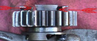
We inspect the teeth of the ratchet: they should be sharp without chips or other damage. If the teeth are wrinkled or broken, the winding foot will slip 100%. Many suffer from this problem due to thick oil or a weak spring - in fact, the reason for the foot slipping lies in the ratchet.
If the teeth on the basket are not worn out, it is advisable to rivet the ratchet: buy a new one in the store or remove it from another basket and rivet it. I riveted several baskets and they went without any problems until the “victory”...
An example of ideal ratchet teeth.
Often and thickly, the rivets on the ratchet weaken and if you don’t notice this in time, they are cut off. To prevent this trouble from happening to you, move the ratchet with your fingers. If it wobbles, drill out the old rivets and rivet them again. Pulling old rivets usually does nothing.
If you are making a clutch “for yourself” and for a long time, be sure to check the condition of the teeth for the motor chain.
If the teeth have already begun to turn back, then such a basket should be immediately thrown into the trash. It will no longer be of any use: the operating noise will increase, it will 100% eat up the motor chain, and there’s never an hour when one “fine” day it will lick your teeth and you will then be forced to push your jalopy for a long time and tediously...
An example of worn teeth.
It is not uncommon for the basket body to burst. Unfortunately, the body is made of cast iron and welding it will be problematic. If you find cracks on the body, try to find a welder who welds non-ferrous metals, the so-called “argon welder”; they usually take on welding cast iron.
An example of cracks in the basket body. By and large, this basket can still be saved: chamfer the cracks, weld and turn the seams on a lathe. But the teeth under the motor chain were worn out and I threw it away.
Pressing the crankshaft
It is not difficult to press the crankshaft, a good crankshaft did not press, I will explain everything in words. It is recommended to compress the crankshaft on an anvil or on an old cast-iron car block. Insert the new pin into the crankshaft cheek where it was when released, this will make it easier to press the second cheek. The new pin is driven all the way from the inside of the crankshaft. Place the new needle bearing and connecting rod onto the pin. Place the crankshaft cheek with the hammered end on the support so that the pin rests against the support. Place the other cheek on your finger and hit it with a heavy hammer, as shown in the photo below.
When driving the second jaw onto the crankshaft, be careful not to touch the threads or taper of the crankshaft axle. You shouldn’t worry too much about the alignment of the crankshafts at this time; it’s enough to get them approximately right.
The roller is pressed, now we check the size between the cheeks with a barbell, if the cheeks are pushed apart less, if more, nail the cheeks to the desired size.
Also be careful that the crankshaft pin does not come out of one of the cheeks, if it comes out with a mandrel, drive it in.
Photo. Squeezing the crankshaft of a motorcycle
Tuning IZ Jupiter 5 – using the bike’s potential to its full potential
[sc:ads1] Bright and unique things have always been a sign of good taste, ingenuity of the owner and his material wealth. The desire to travel on a one-of-a-kind vehicle is even more relevant, since the production of both cars and motorcycles occurs on a mass basis. Hundreds of thousands of identical wheeled units roll off the assembly line every year, making road traffic monotonous and dull. It was especially hard for citizens of socialist countries, where stereotypes were the norm of life.
But resilient drivers, as motorcyclists are by definition, have always very quickly found a way to highlight their vehicle in the gray traffic and make it the envy of others. Everything that was at hand was used - from all kinds of light bulbs, shiny stickers, right down to changes in the frame structure and replacement of the engine . Now, when the domestic motorcycle enthusiast has access to almost unlimited quantities of materials to upgrade his motorcycle, tuning bikes has become a real art.
However, motorcyclists were divided into two groups: some adopted all the features of their Western sister cities without exception, while the other remained faithful to the creations of the Soviet and domestic motorcycle industry. Almost all motorcycles that come to hand are tuned, but some are more popular among those who like to upgrade Soviet two-wheelers. One of these is Izh Jupiter 5.
Adjusting the Clutch Springs
Adjusting the springs is not difficult, the main thing is to get it right. We start by placing the motorcycle on the center stand. Then remove the lid, draining the oil in advance. We squeeze the clutch lever to the limit and be sure to fix it. Next we turn on the speed, preferably the first one. We take the wheel and begin to rotate. We try to determine by touch how much effort we are applying. We look at the coupling as it rotates and determine which springs are loosely tightened. We mark them with chalk, then tighten them. We begin to rotate the wheel again and if you feel that the wheel has become easier to spin, then everything has been done correctly. The process must be repeated to achieve a better result. After this, we check the result obtained while moving. If, as the load increases, the clutch begins to slip. All springs must be tightened using nuts. In this case, all nuts must be turned the same number of turns.
( 2 ratings, average 5 out of 5 )
Source
Tuning the IZH Jupiter engine
Before you start, you need to decide how much power you would like to give to your engine. If you are quite satisfied with the average power, then you will need a ZiD-200 resonator. But if you want to make the IZH Jupiter 5 motorcycle fast and powerful, start tuning the engine by installing a resistor from the SMB-5 “motoblock”.
Replacing the air filter plays a big role in engine modification. The better the air is cleaned, the more horses the engine will be able to produce. After all, the degree of engine overheating depends on the amount of incoming air. It is best to use imported air filters. They provide improved cleaning and longer service life.
Next you should work hard on the injection system. An excellent option is to install a “Planet” carburetor with a diffuser diameter of 0.32 cm. Two carburetors will provide much greater acceleration and good dynamics. We take the flanges securing the cylinder from the standard tube, grind out the aluminum studs, and cut off the flange from the carburetor from the inlet tube from the Planet.
We grind the ends of the cylinder heads on a machine, and press the cylinders themselves. The maximum permissible volume of PIC is 18 cubic meters. see Install factory copper layers under the cylinder heads. And we adjust the ignition advance angle to increase compression.
We use the second flange from the old carburetor. Then we weld the parts using “cold” welding. And finally, we modify the assembly to be compatible with the inlet channels. all the cracks with epoxy liquid . Voskhod carburetors will provide uniform traction. In this simple way, you can add not only a couple of additional horses to your pet, but also provide more lively dynamics that give a good riding experience. The motorcycle is very reliable for everyday use, and if you take good care of it, breakdowns will occur very rarely.
[sc:ads5]
Is it possible to replace the crankshaft cheek by taking it from another?
I did it differently, but it is advisable not to change the crankshaft cheek, since there is a slight displacement from the center of the hole and from the center of the crankshaft, so selecting cheeks from different crankshafts is not possible. It is possible to remove the axial displacement of the shafts. But it happens that even different cheeks sit like a family. The crankshafts are drilled on a machine with settings, if the crankshaft is from a different batch, it means it was drilled on a different machine, but there may be a slight shift of hundredths and tenths of a millimeter, this little thing does not affect the engine in any way, and when assembling the crankshaft from different cheeks, it can be bias.
How did the motorcycle turn out the way it is?
The metal is sanded and coated with clear acrylic varnish. Selected color combinations and everything glossy are still boring from fiddling with computer programs. I wanted something like the so-called post-apocalyptic industrial theme. Here, for example, from the Detroit Bros workshop:
In general, I decided to assemble the Jupiter without the side borders and so that it would all shine with the steel from which it is made.
I bought a kilogram package of car varnish, it turned out to be acrylic, from Vika (about 500 rubles). I also bought thinner for acrylic paints and varnishes, also from Vika (a couple of jars for 90 rubles each), but later the hardener ran out faster than the thinner (a small jar of hardener was included with a jar of varnish). It seems that the domestic solvent R-12 is friendly with any acrylic paints and varnishes, but I have not checked.
I planned to paint with a purchased touch-up airbrush from MATRIX - with a simple round nozzle, a 0.2-liter aluminum tank, designed specifically for regular paint (not for all sorts of filling primers, which require a large diameter nozzle, greater pressure and, accordingly, greater air flow), produces spot from 5 mm to 4-5 centimeters, economically consumes paint.
I bought this touch-up airbrush for 690 rubles. And for 200 rubles a filter drier is small for him, for another 50 rubles for a set of two flanges (for a thin oxygen hose) and two nuts for a bayonet connection of such a flange to the airbrush.
On occasion, I got the compressor quite inexpensively, homemade, from a compressor from a refrigerator, a small receiver, a pressure gauge on the receiver itself, and an oxygen reducer with a thin oxygen hose. I've already modified it a little:
And also modified:
Such a compressor will not handle spray guns with high air consumption, but my touch-up airbrush works, and a small airbrush will work even more so. Although you can try a small spray gun with an LVLP spray system (originally made to work at low pressure and air flow) from IWATA, for example (I saw it on the Internet for 2300 rubles). But the compressor works no louder than a refrigerator. Otherwise, I would buy a compressor from my next salary (this is approximately 5,000 - 7,000 rubles).
Motorcycle design
But structurally the motorcycles of these modifications did not differ from each other. All components of the motorcycle were mounted on a tubular frame. To provide suspension for the rear wheel, there was a subframe at the rear of the frame, attached to the frame by a non-rigid bolt connection. A power unit with a gearbox and a steering column equipped with a telescopic fork were installed on the front part of the frame. The fuel tank was located above the engine, and in front of it was the steering wheel, dashboard and headlight.
Behind the tank, the entire upper part of the motorcycle was allocated under the seat, with a rear fender with a brake light attached to it. Below the seat there were two glove compartments. The left one was for the battery, and the right one was for tools.
The rear wheel was installed on the existing subframe. To provide its suspension, the subframe, in addition to the non-rigid bolted fastening, was connected to the frame by means of spring-loaded oil shock absorbers. The springs had three-position adjustment, which provided a change in the rigidity of the rear suspension. The rear wheel was driven by a chain drive.
Exhaust pipes extending from the engine stretched along the entire motorcycle. To protect the driver and passenger from possible burns, the pipes were attached under the running boards.
The motorcycle was equipped with two-cam drum brakes with mechanical drive on both wheels. Subsequently, some versions were equipped with hydraulic front disc brakes.
Crankshaft alignment
The crankshaft is assembled, all that remains is to eliminate the runout of the shafts (balance), many people think that they cannot do without a lathe, but everything ingenious is simple.
Measure each neck using a barbell as shown in the photo below, they are usually the same size but sometimes vary slightly in size. This dimension must be taken into account when centering the crankshaft.
Photo. We measure the crankshaft cheeks.
All that remains is to attach the rocker arm to the crankshaft cheek as shown in the photo below. It will be like this, first place the barbell on one cheek and press with your finger, the barbell will lie perfectly flat on the cheek, if this cheek is moved up, a gap will appear between the barbell and the second cheek. If the cheek is lower, the bar will be slightly inclined.
Photo. The picture shows a motorcycle crankshaft with a rocker arm, the arrow shows the gap between the rocker arm and the cheek.
Your task is to achieve alignment of the crankshaft cheeks without gaps by applying a rocker arm to each cheek in turn. The photo below shows how you can move the crankshaft cheek using a hammer. Be sure to take into account the strength of the crankshaft cheeks; the crankshaft on which I show from the CHZ section is hot and is not afraid of impacts. But the crankshafts of most road bikes are made of soft metal, so you can only hit where the tire is not applied.
Photo. This way you can move the crankshaft cheek.
If one cheek of the crankshaft turns out to be larger in diameter than the other, then when centering the crankshaft, take into account the gap between the cheek and the connecting rod; visually this gap should be the same by placing the connecting rod against the larger cheek on both sides.
Photo. The crankshaft of the bicycle is centered, the rod rests against the cheeks of the crankshaft without gaps.
If you do everything right, everything will be right, save on a new crankshaft by replacing only the connecting rod with the old one, all you need is your hands and a smart head.
Motorcycle Features
According to industry norm, the motorcycle had an alphanumeric index:
- IZH 7.107-010 – basic model;
- IZH 7.107-020 was already equipped with a new lubrication system and improved front axle suspension. In addition, the wiring diagram of the IZH Planet 5 motorcycle had a contactless ignition system, independent of the battery;
- IZH 7.107-030 was equipped with a spring-hydraulic shock absorber and a redesigned rear wheel brake drive;
- IZH 7.107-040 was produced with modified kinematics and a modified front wheel brake. The wiring diagram on IZH Planet 5 remained contactless until 2008.