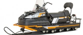
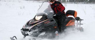
The Buran A snowmobile is a real long-liver in the market of domestic winter all-terrain vehicles. It began to be produced back in 1971. At first, snowmobiles were made only for border guards, foresters and virgin snow explorers. But the equipment turned out to be so convenient that soon hunters, fishermen, and lovers of active winter recreation began to buy it for personal needs. The advantages of the model are that it is maximally protected from rollovers, and is also capable of carrying large loads. Even at a temperature of -30 degrees, the snowmobile remains on the move and does not stall.
Design and main mechanisms
Buran A/AE has a long history, during which the main parameters have remained unchanged. But the design has undergone modifications more than once, striving for modern trends. A couple of years ago, the manufacturer made changes to the appearance of the hood, as well as to its mounting scheme. Now, when tilted, full access to all necessary engine components and assemblies is provided.
The hood is made of injection molded plastic, which is highly resistant to various external influences and impacts. It has quite high strength even at very low temperatures. The level of comfort is increased due to the installation of a high two-level seat on the Buran, which has a removable backrest for the passenger.
There are two versions of the snowmobile - Buran A and Buran AE. Externally, both cars are completely identical, but the model with the letter E has an electric starter. The letter A means that the snowmobile has a short platform. Model catalog number - 110000300 and 110000300 01, respectively
With the help of go-rm.ru and more.
The main role in the creation of the first mass Soviet snowmobile was played by Pavel Fedorovich Derunov, director of the Rybinsk Engine Plant Production Association. The USSR State Planning Committee pushed him to this step: large defense enterprises were supposed to produce consumer goods.
Aircraft engines were made at RMZ. At that time, the plant employed 37 thousand people, and the director did not want to dissipate the enterprise’s capacity into banal “cups and spoons.” I wanted to produce a technically complex product.
Having chosen a worthy product - a snowmobile - the factory workers decided to focus their efforts on producing a stable 2-track machine designed for serious work.
In 1970, the development of a prototype snowmobile began, and already in March 1971, the first BURAN snowmobile with an engine from the IZH-Jupiter-3 motorcycle was manufactured. However, the power of the motorcycle engine was not enough, and in 1971, the RMZ-640 engine was designed for BURAN by the factory.
In April 1972, the first batch of snowmobiles was produced and testing began. Exactly a year later, after the completion of interdepartmental tests, the State Commission decided to put BURANOV into mass production.
To give the new technology a wide resonance and identify its weak points, a long test run was organized along the Rybinsk-Vorkuta route. On March 18, 1973, nine “BURANS” started from Rybinsk, and on April 15, residents of Vorkuta witnessed an unusual sight: a column of snowmobiles with sled trailers passed through the city streets.
The run ended successfully.
At Arctic stations, with temperatures below 30 degrees, starting any engine was difficult - the equipment needed preheating. However, “BURAN” did not need it: in the most severe cold, the snowmobile started up with half a turn.
In 1974, the design bureau began developing the Saturn single-track snowmobile, equipped with an RMZ-640 engine. However, these works remained unclaimed.
In the seventies and eighties of the last century, the production of “BURAN” was on the rise: from a thousand cars in 1973 to 14,750 snowmobiles in 1985. In the first decade, more than 70,000 snowmobiles were produced, but the market was still far from saturation. It was difficult to imagine life in the northern regions of the country without BURANOV. Snowmobiles have found use on fishing collective farms, hunting farms, communications enterprises and on Arctic expeditions. “BURAN” was awarded and twice confirmed with the State Quality Mark.
The design bureau also worked on the future. In 1982, the Icarus single-track snowmobile was designed. At the end of the same year - a 2-track snowmobile with two steerable skis and a closed cabin; in 1984 - a snowmobile for extinguishing fires was designed.
The basic BURAN model received modifications: in July 1982, the company began producing the BARS snowmobile in small series, intended for the military. It featured a searchlight mounted on the hood, could carry a soldier, a walkie-talkie, and tow skiers
In 1986, the hundred thousandth “BURAN” rolled off the production line of the enterprise. However, it was very different from the 1971 model snowmobile. From the moment the production of snowmobiles started, research work on the main components of the machine began. Their result was an improvement in the design, the introduction of new elements or, conversely, a simplification of parts or manufacturing technology.
Some of the research work was carried out with the help of leading institutes of the USSR. In 1988, together with the Leningrad branch of the All-Union Scientific Research Institute of Technical Aesthetics, a single-track snowmobile was developed. They called the car “TAIGA”, anticipating the appearance of the flagship of “Russian Mechanics” by almost ten years.
At the very end of the eighties, the BURAN-M modification appeared. In addition to its unusual appearance, the car received a gas tank increased to forty liters and more power: 35, rather than the standard 28 horsepower. Later the car was called "Arctic".
In the nineties - a “time of troubles” in the new history of Russia - the production of BURAN was also not problem-free. Although the Russian snowmobile market was still far from saturation, the number of vehicles produced had decreased to the level of the seventies. In 1999, only 5,000 cars rolled off the assembly line.
At the end of the millennium, the 2-track BURAN S-640 became the base model of the enterprise. It was produced in three modifications. “BURAN-M” and “BURAN-MD” were also produced with a more modern design, a powerful engine and advanced ski suspension.
In December 1998, the two hundred thousandth “BURAN” rolled off the production line of the enterprise. However, global snowmobile technology has developed more and more rapidly. The time has come to complete the stage of endless modernization of BURAN. In February 1999, the new generation TAIGA snowmobile left the diesel plant building. A year later, its mass production began.
In 2004, the production of snowmobiles was separated from NPO Saturn (formerly) into an independent unit. At the same time, the management of the enterprise decided to expand the model range of manufactured machines: TAIGA and its modifications appeared. The only snowmobile brand in Russia, Russian Mechanics, was created.
In 2006, the share of Russian Mechanics machines occupied almost 50% of the market for all snowmobile equipment in Russia. The company offered consumers almost a dozen options for the Taiga snowmobile.
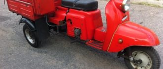
In 2007, the company began developing a “summer theme”: the first all-terrain vehicles and scooters produced by Russian Mechanics appeared on the Russian market.
During this period, a whole line of new models of snowmobiles appeared: at the international automobile show, a new snowmobile “TAIGA” ST-500DR (“Attack”) with a lever suspension and a liquid-cooled engine, and a light snowmobile TIKSY 250 were presented.
Description of the S-640A "Buran" model
“Buran” SB-640A is a series of 2-track snowmobiles of various configurations with an engine start from a manual starter and electric start, with a headlight and a spotlight, an automatic transmission of two versions, ensuring optimal engine operation in any road conditions. It is characterized by high cross-country ability, ease of operation and maintenance, and reliability in operation. Can move in reverse and tow a trailer.
The Buran snowmobile has the following modifications:
- snowmobile "Buran" S-640A1Ts - with a manual starter and an electric starter, with a centrifugal regulator 110602800;
- snowmobile "Buran" S-640A1I - with a manual starter, with a centrifugal regulator 110602800;
- snowmobile "Buran" S-640A1V - with a manual starter and an electric starter, with a centrifugal regulator 110602900;
- snowmobile "Buran" S-640A1G - with a manual starter, with a centrifugal regulator 110602900;
- snowmobile "Buran" S-640A1IP - with a manual starter, with a centrifugal regulator 110602800 and a spotlight;
- snowmobile "Buran" S-640/3700 - with a manual starter, with a centrifugal regulator 110602800, a high-power engine, a spotlight and a 3700 mm long track;
- snowmobile "Buran" S-640M with a manual starter, with a centrifugal regulator 110602800, a high-power engine, an intake muffler and a telescopic ski suspension;
- snowmobile "Buran" S-640MD with a manual starter, with a centrifugal regulator 110602800, a high-power engine, an intake muffler, a telescopic ski suspension and a 3700 mm long track.
Specifications
| Dimensions | |
| Snowmobile length | 2700 mm |
| Body Width | 910 mm |
| Windshield height | 1335 mm |
| Luggage box dimensions | |
| Length | 2420 mm |
| Width | 1060 mm |
| Height | 1130 mm |
| Suspension | |
| Front suspension type | elliptic spring |
| Rear suspension type | independent, spring balanced |
| Front suspension travel | 50 mm |
| Rear suspension travel | 50 mm |
| Number of front springs | 1 PC. |
| Mover | |
| Propulsion type | crawler with front drive sprockets |
| Number of tracks | 2 pcs. |
| Tension mechanism type | screw |
| Track type | rubber-fabric, reinforced with plastic rods |
| Full track length | 2878 mm |
| Width of each track | 380 mime |
| Height of lugs | 17.5 mm |
| Transmission | |
| Type of installed transmission | variable speed drive |
| CVT gears | low (L), high (H), reverse, neutral |
| Brakes | |
| Brake type | disk |
| Brake drive type | mechanical |
| Operating Parameters | |
| Start type of power unit | manual/electric starter |
| Type ignition system | contactless |
| Lubrication system type | joint (mixture of oil and gasoline) |
| Snowmobile structural weight | 285 kg |
| Weight of towed cargo | no more than 250 kg |
| Main fuel tank volume | 28 liters |
| Number of seats | 2 pcs. |
| Maximum movement speed | at least 60 kilometers per hour |
| Exhaust system type | muffler with surround resonator |
| Intake system type | intake silencer |
| Lighting engineering | |
| Headlight type | halogen, 55/60 |
| Tail light type | LED |
Power point
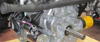
The Buran A/AE snowmobile is equipped with a two-stroke, two-cylinder power plant of the RMZ-640 brand. This engine has a significantly reduced compression ratio, which allows the use of fuel of different brands - AI-92, A-76 and AI-80. Instead of regular gasoline, you can use gas condensate (gasoline) - even with it, the engine confidently develops its maximum power characteristics.
Mikuni brand float type carburetor. The diameter of each cylinder is 76 millimeters. The total working volume is 0.635 liters. The piston stroke is 70 millimeters. At the same time, the RMZ-640 motor is capable of developing a rated output power of 25 kilowatts, which translates to 34 horsepower. The unit is protected from overheating by an air cooling system, which has become standard for all winter cars.
Large traction force is achieved thanks to the large gear ratio of the final drive in the gearbox, the use of an Alpina model variator and a power plant with a fairly large maximum torque. It is worth noting that the engine develops maximum torque at low speeds. This allows you to drag a load weighing more than 250 kilograms without any difficulty.
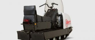
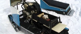
Buran SB-640AD powerful snowmobile with a cargo platform
As part of the line of popular Buran snowmobiles with an extended track, there is the SB-640AD model, whose design and chassis of the snowmobile allows it to transport cargo not only on a trailer, but also on the loading area of the snowmobile itself.
Buran AD is a new modification of the SB-640MD, for which the Buran Arktika was the base model. The technical indicators and equipment of these snowmobiles coincide in many respects.
The nominal operating mode of the engine is provided by an automatic transmission of two versions. Brakes - disc and hydraulic, chain drive, 1-speed gearbox with reverse. In the basic Buran model and in subsequent models, the service life of the gearbox was increased by installing a tensioner on the chain.
The SB-640AD has a snowmobile chassis equipped with a roller balancer, which made it possible to place a platform for small loads on the snowmobile. This design solution immediately attracted the attention of fishermen and hunters. Snowmobiles are equipped with serial, powerful engines. They operate stably at low and medium speeds and are economical - the snowmobile consumes 21 liters per 100 km of heavy road.
Starting the engine is possible in two versions - manual (MA) and electric starter (ADE). The launch parameters are reflected in the configuration number and therefore the cost of the snowmobile for the AD variant is ~180,000 rubles, and for the ADE variant ~200,000 rubles.
Snowmobiles, thanks to the design of elongated tracks, have good traction when moving on loose snow on slopes of up to 20 degrees. Buran's chassis allows for reversing and turning with a radius of 8 meters.
Technical characteristics of the Buran SB-640AD :
- Total length 2845mm
- Length without ski 2665mm
- Width with skis 900mm
- Height with glass 1320mm
- Track dimensions 3686.5x380mm
- Dry weight 310kg
- Gross trailer weight 500kg
- The volume of the gas tank is 28 liters.
- Engine PM3-640
- Forced-air cooling
- 2 strokes, 2 cylinders 1 carburetor
- Cylinder diameter 76mm
- Piston stroke 70mm
- Volume – 635cc
- Operating power - 34hp
- Gasoline – AI-80
- Speed max 55 km/hour.
The SB-640AD model has a snowmobile chassis equipped with a particularly durable ski suspension, and in addition, to improve visibility in difficult conditions, in addition to the main headlight, a rotating spotlight is included in the kit. These and other ergonomic design improvements provide driver comfort and the ability to carry heavy loads in snowy terrain.
Buran SB-640AD is a reliable snowmobile with increased load capacity.
Chassis
The snowmobile has one steering ski and two rear tracks. Thanks to this, the car is not afraid of stumps, snags, bushes and tree branches that can cause damage to the chassis. The use of exactly two tracks had a positive effect on the vehicle’s maneuverability, since their total area ensures low specific pressure.
Another key point is maneuverability. With this, everything is great with Buran, since one swivel ski, combined with a fairly short longitudinal base of the equipment, allows you to maintain nimbleness in rather cramped conditions, for example, to easily go around trees in forest areas. The modernized frame, which received a front bevel in the tunnel, coupled with increased ground clearance, allows you to easily move through deep snow.
It should be emphasized that the Buran A snowmobile is very simple and unpretentious in further maintenance. Spare parts are easy to find. The machine has excellent maintainability even in field conditions far from civilization.
Alex Motors 1161 units of equipment sold. You can trust us!
The reason for writing this article was the numerous requests from owners of Buran snowmobiles, and the frightening statistics of accidents as a result of snowmobile failure (failure of a counterfeit engine) in the harsh conditions of the Far North.
As a result of long-term communication with numerous owners of Buran snowmobiles from all over Russia, we found out that along with the original factory engines, numerous sellers of snowmobile parts successfully sell “left-hand engines” of garage assemblies. More or less honest sellers offer counterfeit engines such as a Rybinsk-assembled engine, a non-branded engine or a hand-assembled engine; others, deceiving the buyer, sell them as original; still others don’t make any distinctions at all, a new engine for Buran and okay...
Some buyers deliberately purchase counterfeit engines for reasons of economy - sellers usually offer them 3-5 thousand cheaper than the original one and at the same time brazenly deceive that it is better - supposedly it is assembled from all original parts and also by hand, but not at the factory. And so the buyer installs a counterfeit engine on his snowmobile (airboat) and goes into the cold into the tundra (forest, field, taiga) perhaps forever...
Now let's look at this problem in more detail:
During assembly, an original crankshaft (costing 10,000 rubles) is installed on the original engine; the famous Chinese crankshaft (costing 1,500-2,000 rubles) is installed on the one that is assembled in the garage.
The original engine is equipped with Czech pistons, Czech piston rings, Austrian pins, Japanese needle bearings, original cylinders, Ufa or Moscow (Flames) ignition, original carburetor, etc., and there is even fasteners - bolts, washers and nuts of the required strength class. And for counterfeit they put Chinese pistons, rings, pins, bearings, carburetors, Chinese or, at best, Irbitan restored cylinders, etc.
At JSC Russian Mechanics, engines are assembled manually by qualified assemblers under the highest quality control of the assembly from high-quality parts and a warranty period of 6 months. With proper operation, this period overlaps several times. — In the garage, the “engine” is assembled by someone unknown, under what control, but it is clear from what spare parts - the cheapest and, of course, without any guarantees - whoever has encountered it knows - well, what kind of guarantee can there be for a Chinese crankshaft?
And in the end, the buyer will not receive any benefit if he purchases a slightly cheaper counterfeit assembly. The buyer purchases an assembly made from low-quality spare parts at exorbitant prices...
We (we will not advertise our name so as not to be considered advertising) have sold a large number of original engines and there have not been any serious complaints about their performance. Moreover, reliability is evidenced by the fact that the RMZ-500 engines were loved by our aviators, who preferred them to their foreign counterparts. This kind of trust is one thing to drive on the ground and a completely different thing to fly through the air.
We hope you have decided on the choice of engine - you go to a spare parts store, inspect the engine, but how can you determine whether it is an original or a fake? The information below will help you with this issue, and will also help you identify a dishonest seller and, in the case of a purchase already made, will help you get your money back for the purchased counterfeit engine!!!
1. The original engine is shipped from the factory in the original cardboard packaging with the “RM” logos (see photo). The packaging is quite good, suitable for transportation. If you are offered an engine without this packaging, you should ask why?! Well, suppose the seller says that it got wet from the rain or something else and lost its presentation... If the packaging is present, then there should be a tag glued to the side (see photo) with catalog numbers, logos and, most importantly, the engine number.
2. We continue the inspection further - we ask and study the engine passport. The passport must be of the same type as in the photo below.
3. Next, compare the engine number on the box, in the passport and the number on the crankcase to the right below the carburetor (intake manifold) as indicated by the arrow in the photo.
4. It seems to calm down here, but the most important thing is ahead. Please pay attention to the manual starter and the metal adapter to the carburetor (to the right of the carburetor) - on original casting engines there should be raised “RM” logos as in the photo. If they are not there, this is definitely a fake!!!
5. Then we check for the presence of raised logos on the fan housing (the photo also shows the original Czech Rubena fan belt) and on the square motor casing. On the carburetor (provided that the engine has a K-65Zh carburetor) on the left we read the marking CW-65J Zh and below the WEBER company we see an installed throttle cable on top.
6. We also pay attention from the side of the variator installation to the original designation of the cylinder 110500064 and below YL 112 to the original crankshaft cuff from KOC and to the technological plate instead of the engine base. Since February 2013, Russian Mechanics OJSC has not supplied engines with engine bases.
7. The spark plugs on the original A 17 DV engine, such as those in the photo below, are light in color, not black.
8. The ignition system installed on original engines is clearly visible in the photo below along the wiring harness, connectors and switch K-1B.
If all the above conditions coincide, we can say with confidence that this is an original RMZ-640-34 engine manufactured by RUSSIAN MECHANICS OJSC.
Buran engine configuration:
110502600 110502600 ZCh (RMZ-640-34) - Manual starter, domestic carburetor.
110502600-01 110502600-01ЗЧ (RMZ-640-34) - Electric starter, Manual starter, domestic carburetor.
110502600-02 110502600-02ЗЧ (RMZ-640-34) - Manual starter, Minkuni carburetor
110502600-03 110502600-03 ZCh (RMZ-640-34) - Electric starter, Manual starter, Mikuni carburetor.
How much does it cost and where to buy
The cost of the new Buran A/AE when purchased directly from the manufacturer will be equal to 259 thousand rubles. But delivery is carried out only in the Moscow and Yaroslavl regions. Residents of other regions should contact dealers. Their price will be more expensive, since it includes the cost of transportation from the manufacturer’s warehouses (the vehicle will cost 265-280 thousand rubles, depending on the region).
A used snowmobile costs much less - from 185 thousand rubles to 220 thousand Russian rubles. The price of a used version depends on the year of production, general technical condition and the number of kilometers traveled.
If your snowmobile breaks down or you decide to take a faulty Buran, you will need spare parts. They can be purchased at any specialized motorcycle parts store. Approximate prices for components (in rubles):
| Engine block RMZ-640-34 assembled | 32100 |
| Crankshaft Buran RM 110504240 | 16500 |
| Cylinder head | 1780 |
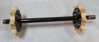
| Drive shaft with sprockets | 1090 |
| Guide shaft assembly | 1489 |
| Caterpillar composite MD | 10000 |
| Balancer trolley 3-spring | 1560 |
| Buran A reinforced hood | 4800 |
| Front headlight Buran A | 960 |
| Rotating spotlight | 1150 |
| Rear trunk | 5340 |
| Bumper Buran A | 920 |
| Seat Buran A | 1950 |
| Ski Buran | 1930 |
| Fan assembly | 5660 |
| Brake assembly | 2030 |
Engine RMZ-640 “Buran” Description, modernization.
DESCRIPTION
The RMZ-640 engine
is a two-cylinder, two-stroke with loop crank-chamber purge, carburetor, forced air cooling.
The main mechanism of the engine (Fig. 2) is a crank mechanism designed to convert the rectilinear reciprocating movement of the pistons into the rotational movement of the crankshaft.
Crankshaft.
The three-bearing crankshaft consists of a right 46 and a left 3 axle, cheeks 8 with a crank pin and a middle shaft 49, interconnected by press fits. The crankshaft is supported by three ball bearings 4 mounted on the middle shaft and journal journals. Rubber rings 6 and 47 located in the grooves of the outer races of the bearings and labyrinth seals serve to equalize the loads on the crankshaft support bearings. The axial movement of the crankshaft is limited by the thrust of the trunnion bearings into the retaining rings 7 installed in the corresponding grooves of the crankcase. The ends of the crankshaft emerging from the crank chambers of the crankcase are sealed with cuffs 5. The necessary radial pressure of the sealing edge of the cuff and its constant contact with the shaft are ensured by a spiral bracelet spring.
Connecting rods
12 provide a hinge connection between the piston and the crankshaft. The main elements of the connecting rod are the upper (piston) and lower (crank) heads and the I-section rod connecting them. Needle bearings 16 and 9 are installed in the holes of the upper and lower connecting rod heads. The radial clearance in the bearings of the upper and lower heads is 0.012...0.024 mm. The specified gap is ensured by sorting by diameter into size groups of bearing rollers, piston and crank pins, and corresponding connecting rod holes. The connecting rod hole group is marked on the rod under each head. The holes made in the lower head of the connecting rod, as well as the flats on the end surface of the head, serve to lubricate the bearings.
Rice. 2 - Engine:
1 — engine base; 2 - lower half of the crankcase; 3 — left axle; 4 - bearing; 5 - cuff; 6 — shock-absorbing ring; 7 — retaining ring; 8 - cheek; 9- needle bearing; 10 - upper half of the crankcase; 11 - gasket; 12- connecting rod; 13 — left cylinder; 14 — piston pin; 15 — retaining ring; 16- needle bearing; 17- piston ring; 18- gasket; 19- left piston; 20 - left cylinder head; 21 — right cylinder; 22- piston right; 23 — right cylinder head; 24 — fan impeller; 25 — bearing; 26 — adjusting ring; 27 — retaining ring; 28 — fan housing; 29- driven pulley; 30 - fan belt; 31 — air intake;
Pistons.
The engine is equipped with left 19 and right 22 pistons that are not interchangeable with each other. The piston has an upper part, called the piston head, and a lower guide part, called the skirt.
32 — adjusting washer; 33 — segmental key; 34 - nut; 35 — fan roller; 36 — drive pulley; 37 — segmental key; 38 — manual starter; 39 - bolt; 40- nut; 41 — hairpin; 42- Magdino rotor; 43 — Magdino stator; 44- hairpin; 45 - nut; 46 — right axle; 47 — sealing ring; 48 - labyrinth; 49 — middle shaft; 50- nut; 51 — electric starter; 52 - nut; 53 — hairpin; 54 — exhaust manifold; 55 — hairpin; 56 - nut; 57 — gasket; 58 - nut; 59 — hairpin; 60 — spark plug; 61 — intake manifold; 62 — sealing ring; 63 — adapter; 64 - nut; 65 — hairpin; 66 — carburetor; 67 — hairpin; 68 - nut; 69 — air cleaner; 70 - screw; 71 - fuel pump; 72 — fuel pipe; 73 — bolt (plug); 74 — bushing; 75 — washer; 76 - nut; 77 — hairpin; 78 - gear
For piston rings, two annular grooves are machined on the side surface of the head. Steel locking pins in the grooves prevent the piston rings from turning and lock each ring into position. As a result, the piston ring locks do not fall into the cylinder windows during piston movement, which protects the rings from damage. In the middle part of the piston there are bosses (bosses) with holes for installing the piston pin. For the piston pin retaining rings, annular grooves with recesses are made in the bores of the bosses. Two small holes on each piston boss are designed to supply lubricant to the friction surfaces of the piston pin-piston connection. The gap between the piston skirt and the cylinder on a cold engine is 0.14...0.16 mm. If the engine overheats, the piston may jam in the cylinder. To ensure selection of liners, pistons are produced in three size groups: M, S, B (small, medium, large). The designation of the size group is marked on the inner belt of the piston skirt. Based on the diameter of the hole for the piston pin, pistons are sorted into two size groups; the group is marked with white or black paints. When changing the piston, it is necessary to install a piston of the corresponding group. The pistons are installed in the cylinder so that the U-shaped recesses of the piston skirt coincide with the purge channels in the crankcase, and the holes in the bosses for the piston pin coincide with the bearing of the upper head of the connecting rod. The difference in weight between pistons installed on one engine is no more than 3 g.
Piston ring.
The pistons are equipped with two piston rings 17, made of high-strength cast iron. Engines can use trapezoidal or rectangular rings.
A thermal gap is provided in the ring lock, since during operation the piston ring expands due to heating. After installing the rings in the engine cylinder, the gap should be: 0.40...0.55 mm for trapezoidal rings and 0.25...0.45 mm for rectangular rings. To obtain the specified gaps, filing the ends of the lock is allowed.
The gap between the ends of the ring and the grooves when compressing the ring to a diameter of 76 mm should be 0.06...0.15 mm for rings of trapezoidal cross-section and 0.080...0.115 mm for rings of rectangular cross-section.
Since piston rings operate at a very high temperature, oil, getting into the gap between the overheated ring and the piston groove, cokes, that is, carbon deposits and resinous substances are formed, which leads to burning of the rings. This causes a deterioration in the starting quality of the engine and a decrease in the power developed by the engine. If carbon deposits are not removed in a timely manner, the engine may fail. The top ring has the greatest tendency to burn. Burning of piston rings most often occurs from engine overheating due to improper operation, as well as due to wear of the ring or cylinder. The piston pin is designed to articulate the piston with the connecting rod. The piston pin is installed in the bores of the piston bosses with a tight fit. Based on their outer diameter, piston pins are sorted into two size groups. The group is marked with white or black paints at the end of the finger. When assembling, the pin and piston are selected from the same group.
Cylinders.
The left 13 and right 21 cylinders installed on the engine are not interchangeable with each other and consist of an aluminum jacket and a cast iron liner pressed into it. To ensure selective assembly of the liner-piston interface, the cylinders are available in three size groups. The size groups are designated by the letters: M, C, B and are marked with impact on the collar of the lower flange of the cylinder. When changing a cylinder, it is necessary to install a cylinder of the corresponding group. The cylinder is mounted on the engine crankcase with the lower flange, and the cylinder head is placed on the upper flange. A sealing steel-asbestos gasket 18 is installed between the head and the cylinder. When overhauling the engine, the gasket can be reused. Paronite gasket 11 seals the joint between the lower cylinder flange and the crankcase supporting plane. Each cylinder with a head is secured to the crankcase using four studs.
Cylinder heads. The left 20 and right 23 cylinder heads are made of aluminum alloy. The body of the combustion chamber head has a threaded hole for installing a spark plug. To avoid unacceptable deformation of the head and cylinder during assembly, the stud nuts are tightened crosswise in two steps: first preliminary, and then finally with a tightening torque of 2.0...2.5 kgf-m. In this case, the intake manifold mounting nuts must first be tightened. The nuts should be tightened or tightened when the engine is cold.
Carter
is the main body part of the engine. The crankcase consists of two halves made of aluminum alloy. The halves of the crankcase are connected to each other by pins screwed into its upper half; the nuts securing the crankcase halves are tightened with a torque of 3.0...3.5 kgf-m. Both halves of the crankcase are processed together and are therefore not interchangeable. Each cylinder with cylinder head is attached to the crankcase with four studs screwed into the threaded holes of the support flange. The crankcase connector planes are lubricated with sealant during assembly.
The ends of the crankshaft emerging from the crank chambers are sealed with self-clamping cuffs. The crank chambers are isolated from each other by labyrinth seals installed at both ends of the middle crankshaft support bearing.
Magdino base and fan housing
installed on the flange of the right side of the crankcase; The fan housing is secured to the flange with four studs, and the Magdino base with two screws. The fuel pump is secured to a boss in the upper part of the crankcase with two screws. On snowmobiles "Buran" S-640A1Ts and S-640A1B, there is a boss with two studs for attaching the electric starter bracket to the rear side of the crankcase. Four studs screwed into the bosses of the lower half of the crankcase serve to secure the engine to the sub-engine base. Two threaded holes are designed to drain oil and fuel when depreserving the engine and flushing the crankcase. To ensure the tightness of the crankcase, copper gaskets are installed under the heads of bolts 73 screwed into these holes.
Engine cooling.
When the engine is running, the temperature of the heads should not exceed 200 °C. Since the engine is closed by the hood, and its cooling by counter flows of air through the hood grilles is not enough, to maintain the engine temperature within the limits that ensure its normal operation in all operating modes, an air cooling system is used, which includes an axial blower fan and blower casings.
The basis of the fan is an impeller 24, mounted motionless on a roller 35. In the housing, the impeller is mounted on two ball bearings 25, which have a double-sided seal and are filled with working lubricant at the factory. The impeller is driven by a V-belt 30 from a drive pulley 36 mounted on three studs 41 of the Magdino rotor. At the end of the impeller shaft, a driven pulley is installed on a key, consisting of two profiled half-pulley disks 29. The pulley fastening nut is tightened with a torque of 5...6 kgf-m. The fan housing 28 is mounted on four flange studs on the right side of the engine crankcase. A plastic air intake 31 is installed at the fan inlet.
The belt is tensioned by moving the adjusting washers 32 located between the half-pulleys to the outside of the rear half-pulley. In this case, the top of the stream angle, moving from the center, increases the working diameter of the driven pulley and thereby the belt tension. When operating the engine, it is necessary to periodically check the tension of the fan belt. Under a force of 4±0.5 kgf, the belt should bend by 6...15 mm. Too little tension causes the belt to slip at high engine speeds and cause it to delaminate due to heating; too much tension damages the impeller bearings. Lubricant should not be allowed to come into contact with the belt, as it will destroy the belt and cause it to slip.
Starting system.
For electric starting of the engine (on snowmobiles “Buran” S-640A1Ts and S-640A1V), an electric starter ST362A is used, the design and operation of which are described in the “Electrical Equipment” section. In addition to the electric starter, the engine is equipped with a mechanical starting device (recoil starter), which allows you to start the engine at low ambient temperatures, failure of the electric starter, and also in cases where the battery is discharged by more than 25%.
The engines of the Buran snowmobiles S-640A1I, S-640A1G, S-640A1IP, S-640/3700, S-640M and S-640MD are not equipped with an electric starter.
Recoil starter
(Fig. 3) is located on the right side of the engine and is secured to the fan housing with four screws. Housing 11 houses starter pulley 12 with ratchet mechanism parts. The axis of the pulley is bushing 8, pressed onto the central boss of the housing. The parts are installed on the bushing in the following order: washer 14, pulley 12 with two plastic
Rice. 3 - Manual starter:
1 — lever; 2 - cam; 3 - bushing; 4 - shock absorber; 5 - bushing; 6 - handle; 7 - lock; 8- bushing; 9- washer; 10- spring washer; 11 — body; 12 - pulley; 13 — spiral spring; 14-washer; 15 - cable; 16 - cover
cams 2, a return spring 13 and a steel cable 15 wound into a pulley groove, washer 9, spring washer 10 (to eliminate axial play between parts), lever 1, into the grooves of which the fingers of the cams are inserted, after which the lever on the axis is fixed with a spring lock 7. The return spring of the pulley is made of a spiral, its ends are bent. The outer end of the spring is engaged with the cast protrusion of the pulley, and the inner end is engaged with the protrusion of the housing. If you look at the pulley from the spring side, the spring winding should be directed counterclockwise, the cable winding should be clockwise. The assembly of the starter is completed by connecting the end of the cable to the handle. To do this, by rotating the pulley counterclockwise, the end of the cable is brought out through the housing boss hole, bushing 3, plastic handle 6 with rubber shock absorber 4, and the end of the cable is secured with bushing 5 in the handle. The starter works as follows. When the cable handle is sharply pulled towards itself, pulley 12 begins to rotate, twisting the return spring 13. Lever 1 is motionless at this moment, since its rotation is prevented by the friction of the spring lock 7 about the axis of the housing. As a result, cams 2, moving along the grooves of lever 1, move apart and engage with the internal protrusions of the fan drive pulley - the engine crankshaft begins to spin up. After starting the engine, the protrusions of the fan pulley press out the cams, and the connection between the crankshaft and the starter pulley stops. If you release the cable handle, the pulley, under the action of the return spring, will begin to rotate in the opposite direction, winding the cable, and the cams will take their original position.
In the event of failure of the manual starter, an emergency engine start is provided. Start the engine from the emergency system according to the instructions in Section 4 “Preparation for work and operating procedures”.
Supply system
engine includes a fuel tank with an intake filter in the tank, a sediment filter, a manual booster pump, a carburetor with a fuel pump, an air cleaner (except for Buran snowmobiles S-640M and S-640MD), an intake noise muffler (only on Buran snowmobiles "S-640M and S-640MD) and fuel lines.
Fuel tank
made of polyethylene and installed in the front of the frame. The filler neck of the tank is closed with a lid. A small hole in the lid connects the fuel tank to the atmosphere and prevents vacuum from occurring in the tank as fuel is consumed. To access the filler neck, there is a hatch with a lid in the hood.
The hole in the top of the tank is intended for the fuel intake fitting. The fitting is secured in the hole with a rubber bushing. At the end of the receiving tube of the intake fitting there is a fuel filter with a filter element made of a metal mesh. The hole on the right side of the tank, hermetically sealed with a plug, is a technological hole.
Fuel line
consists of separate rubber and polyurethane tubes connecting the fuel tank to the carburetor.
Settlement filter
(see Fig. 4) serves to clean fuel from mechanical particles and condensate.
Rice. 4 – Settling filter:
1 - body; 2 - glass; 3 - bracket; 4 — glass holder; 5- nut; 6- screw; 7- mesh; 8- gasket; 9 - gasket; 10 - fitting
The main parts of the settling filter are body 1 with a fitting screwed into it and a glass 2. Between the body and the glass there is a filter mesh 7 and a rubber gasket 8. The settling glass is secured to the body with a screw 6, a nut 5, a wire bracket 3 and a holder 4. A transparent glass allows you to observe the amount of sediment accumulated in it and clean it in time.
The sediment filter is fixed to a bracket welded to the “bed” of the fuel tank.
Manual booster pump
Designed to pre-fill the fuel system immediately before starting the engine. The use of manual fuel pumping greatly facilitates starting a cold engine at low temperatures.
A snowmobile can be equipped with a piston-type pump or a manual booster pump, which is a rubber “bulb”. The arrow on the bulb body shows the direction of fuel pumping. To fill the fuel system, you need to squeeze the bulb several times.
The control knob for the piston fuel pump is located on the instrument panel. To fill the fuel system, you need to pull out and press the pump handle several times. To prevent fuel leakage, press the pump handle all the way.
Air purifier.
The air purifier installed on the Buran snowmobiles S-640A1TS, S-640A1I, S-640A1V, S-640A1G, S-640A1IP, S-640/3700 is designed to clean the air entering the carburetor. The air cleaner is attached to the carburetor by two springs. The air purifier consists of a plastic housing and cover, and a mesh filter element. The lid is held on the filter housing by an elastic lock formed by annular protrusions on the housing and the lid. Intake silencer. On snowmobiles "Buran" S-640M and S-640MD, to reduce the level of external noise, an intake noise muffler is installed at the inlet of the carburetor, which simultaneously performs the function of an air purifier.
The carburetor is designed to prepare the fuel-air mixture for the engine. The Buran snowmobiles S-640A1TS, S-640A1I, S-640A1V, S-640A1G, S-640A1IP, S-640/3700 use the K65Zh carburetor.
Carburetor K65Zh
(Fig. 5) single-chamber horizontal with a central location of the float chamber and a flat throttle of the vertical stroke, consists of three main parts: body 12, float chamber 26 and body cover 34. The carburetor is attached to the adapter through a heat-insulating spacer with two nuts. The joints of the connectors are sealed with steam-nit gaskets.
The carburetor body contains: fuel and air channels of the metering systems, nozzle chamber 29, throttle 31 with metering needle 21, throttle spring 35, idle fuel nozzle 23, nozzle 25 with main fuel nozzle 24, fuel inlet fitting, float retainer 18, adjusting screw idle mixture quality 11 and fuel corrector parts. The body is equipped with a flange through which the carburetor is attached to the engine.
The carburetor cover contains a stop 1 for the throttle control cable sheath and an adjusting screw 3 with a rod. The cover and float chamber are connected to the carburetor body with screws.
The float mechanism consists of two rectangular plastic floats 19, connected to each other by a common lever. The axis 27 for attaching the float mechanism to the columns of the carburetor body is inserted into the lever.
The fuel shut-off valve 20 is made in the form of a needle, which rests with its lower part on the float lever, and the upper part (with a washer made of elastic material) closes the fuel supply channel.
The starting device (corrector) consists of a plunger 16 with a metering needle 17 and a spring 15. The fuel intake part of the corrector is located in the well of the float chamber 26, which communicates with the main volume of the chamber through a calibrated hole; the upper part of the corrector consists of a plunger guide spring with a stop 14 of a cable sheath 13 attached to the plunger 16. The nozzle of the main dosing system consists of two parts: a housing 30 and a nozzle 25 pressed into it. The nozzle body has four radial holes. The nozzle chamber is attached to the carburetor body by the spray body.
The throttle 31 of U-shaped section is made of brass sheet. In its wall facing the air cleaner, a radial cutout is made from below, providing a given vacuum above the atomizer. The dosing needle 21 is made of stainless steel and has five grooves for the lock. By rearranging the lock in the needle grooves, it is possible to change the composition of the mixture.
When the engine is running, fuel from the tank enters the float chamber under pressure created by the diaphragm 9 of the fuel pump, which is driven by pulsating pressure from the engine crankcase. The fuel supply is automatically regulated by a fuel needle valve 20 connected to a hollow float 19. The float and needle valve ensure a given fuel level in the float chamber. When the engine is running at low idle speed (throttle 31 in the lower position), the vacuum in the diffuser is small and fuel is not sucked through the main metering system.
The composition of the fuel mixture when the engine is idling is regulated by screw 11, the speed is controlled by screw 3. The required (most favorable) mixture composition when the engine is operating under load conditions is ensured by the position of the conical metering needle 21 relative to the sprayer and the nozzle 23 in conjunction with the operation of the idle system.
To quickly and completely fill the float chamber with fuel at the time of start-up, a float sink 18 is used.
Rice. 5 - Carburetor operation diagram:
1 — stop of the throttle control cable sheath; 2 — throttle control cable; 3 — idle speed adjustment screw; 4 - pump housing; 5 - mesh filter; 6 — filter cover; 7- pump cover; 8- intake valve; 9- diaphragm; 10- exhaust valve; 11- screw for adjusting the quality of the idle speed mixture; 12- carburetor body; 13- corrector control cable; 14- stop of the plunger cable sheath; 15- plunger spring; 16- plunger; 17 — metering needle of the fuel corrector; 18 — float sink; 19- float; 20 - fuel valve; 21- dosing throttle needle; 22 — lock washer; 23 — idle fuel jet; 24 — main fuel jet; 25 - sprayer; 26 — float chamber; 27 — float axis; 28 — gasket; 29 — nozzle chamber; 30 — spray body; 31 — throttle; 32 — plastic fixing sleeve; 33 - gasket; 34 — housing cover; 35 — throttle spring; 36 — stop-limiter; 37 — throttle needle lock; A - air channel; B — venting channel of the float chamber; B — idle air channel; G — emulsion channel of the fuel corrector; E - idle emulsion channel; F - transition hole; And - air channel of the fuel corrector; D - dosing hole in the wall of the corrector well
The Buran S-640M and S-640MD snowmobiles use a Mikuni VM-36 carburetor of the same type as the K65Zh carburetor, but with a cylindrical throttle.
Rice. 6 - Fuel pump:
1 - pump cover; 2 - diaphragm; 3 - body; 4 - gasket; 5 - fitting; 6 - gasket; 7 — sump cap; 8 — bracket; 9 - nut; 10- screw; 11- mesh filter; 12- valve; 13 - valve membrane
A diaphragm type fuel pump is used to supply fuel from the tank to the carburetor. The pump is attached to the engine crankcase with two screws. A steam-nitrate gasket is installed between the pump flange and the crankcase. The main parts of the pump (Fig. 6) are housing 3 and cover 1. Between the housing and the cover there is a diaphragm 2 made of gasoline-oil-resistant rubberized fabric. The suction and discharge valves are non-separable plate type. A strainer I is installed in front of the receiving channel of the suction valve 12. The sump cap 7 is pressed to the pump body using a nut 9, a screw 10 and a wire bracket 8. The necessary seal between the pump body and the sump cap is made by a rubber gasket 6.
Exhaust system.
The purpose of the exhaust system is to remove exhaust gases from the engine cylinders into the atmosphere and reduce exhaust noise. The exhaust system includes a muffler and a connecting pipe through which the muffler is connected to the cylinder exhaust pipe. The muffler consists of a housing, two covers, inner and outer hemispheres and three expansion chambers communicating with each other using pipes. The muffler is attached to the snowmobile body and engine by springs.
Engine mount
(Fig. 7). The engine location on the snowmobile is front transverse. On the snowmobile frame, the engine with a sub-motor base is fixed at four points. An elastic engine mount reduces the transmission of vibration from a running engine to the snowmobile frame, as well as the transmission of shocks and vibrations to the engine that occur when the snowmobile moves.
The elastic mounts of the engine mount consist of rubber shock absorbers 5, mounted on nuts 6 and bushings 13. The nuts themselves are screwed onto fastening bolts 2 and 12, inserted by square headrests into the holes of the frame from the bottom side. The sub-engine base 7 together with the engine is installed on the supports so that the bushings and nuts 6 fit into the holes of the springs
Rice. 7 — Engine mount:
1 - nut; 2 - bolt; 3 — washer; 4 - spring; 5 — shock absorber; 6 - nut; 7 - base; 8- hairpin; 9- nut; 10 — spring washer; 11 — washer; 12 - bolt; 13 — bushing; 14 — washer of the engine base. The shock absorbers are tightened with fastening nuts 1 until washers 3 and 14 stop at the ends of nuts 6 and bushings, respectively. The tightening torque of the nuts is 2.2…2.5 kgf-m.
The removable engine base, consisting of the base itself and two strips with springs, simplifies installation and removal of the engine from the snowmobile frame. The engine is attached to the sub-engine base using four studs screwed into the bosses of the lower half of the crankcase. To ensure adjustment of the distance between the variator pulleys, which is done by moving the engine, there are grooves in the sub-engine base for the engine mounting studs. After adjusting the distance between the pulleys, the nuts securing the engine to the sub-motor base are tightened with a torque of 5.0...5.1 kgf-m. During operation, the tightness of the nuts must be periodically checked, since engine displacement leads to rapid failure of the variator belt.
MODERNIZATION
The RMZ-640 engine was manufactured for the Buran snowmobile by the Rybinsk Engine Plant. This is where the name of the engine comes from. But snowmobiles are designed for use in winter and in areas where snow cover prevails, and, therefore, frost. Therefore, the temperature regime of the engine and air cooling were deliberately planned with a reserve, taking into account the sub-zero operating temperature. And SLA owners operate their equipment mainly in spring, summer and a little in autumn. That is, in the warm season, when the street is not lower than +16 degrees.
Now about the engine. The engine itself has a large reserve of liter power. After all, it has 640 cubic meters. cm, less than that of Rotax-503. If you make a rigid crankcase, correctly position the crankshaft supports on the bearings, make engine parts from nothing and not using consumer goods technology, then according to calculations this engine can produce at least 62 hp. Unfortunately, we live in a country where the most the good and the advanced are not introduced into our daily lives. We are content with what we have. The constant lack of money to buy expensive engines forced us to constantly analyze the capabilities of our domestic engine and still “squeeze out” a power of 40...45 hp from the “skilled hands” set.
To increase the power and acceptable stability of the engine, it is proposed to carry out the following list of measures:
- Replacing crankshaft oil seals with others (oil seal from Moskvich-412).
- Manufacturing of a new oil seal housing (material D16T or equivalent).
- Drilling additional ventilation ducts to lubricate oil seals and bearings.
- Installation of additional 2 middle bearings instead of one on the crankshaft between the middle flywheels.
- Installation of deflectors between the cylinders and at the air flow outlet behind them.
- Balancing pistons with a weight difference of no more than 1.5 grams.
- Thermal insulation of the exhaust manifold with asbestos cord.
- Installing the cylinders in height so that the edges of the cylinder inlet and outlet ports coincide with the edges of the piston skirt and bottom, respectively (to match the phases of the release of the air mixture on both cylinders).
- Installation of a resonant pipe with a noise suppressor
The weak rigidity of the crankcase and the large cantilever of the crankshaft between the three supports are the causes of crankcase deformations during engine operation. Because of this, large loads are placed on the bearings, which, without proper lubrication, create significant rolling and friction resistance. This is also facilitated by the retaining rings of the bearings against the longitudinal displacement of the crankshaft in the engine crankcase, which stand without clearance. When heated, the crankshaft tends to expand, but there is no required temperature gap, so the usual bearing jamming occurs. The bearing begins to heat up and the engine cannot develop the proper speed. For normal operation of the crankshaft, it is necessary to install two bearings and an oil seal in the middle zone between them (instead of one bearing and two labyrinth seals).
Due to the vibration of the shaft consoles (the flywheel-McDino, on the one hand, and the gearbox coupling, on the other) and without proper, but not supplied lubrication, the crankshaft seals are severely worn out, which also “dull” from overheating. The result is air breakthrough through the oil seal and a depletion of the air-fuel mixture in the engine crankcase. The consequence is very deplorable - burnout of the piston or melting of the piston bottom opposite the exhaust port. The engine does not want to continue and should not work, it simply “caught a wedge”. The pilot has to rely only on himself.
To improve the airflow of the rear cylinder, I installed additional deflectors, which provided each cylinder with its own flow of cold air. Now the front cylinder does not heat the rear. Additional winding of the exhaust manifold with asbestos cord on silicate glue also contributes to less heating of the air flow that the fan drives to the cylinders.
Due to the “high-quality” technology of manufacturing the parts of this engine from “something” and “somehow”, the pistons have a difference in weight. There are even untreated flashes after casting. The difference in weight reaches 20 grams. An unbalanced connecting rod-piston group disrupts the smooth, stable operation of the engine, resulting in high vibration. To adjust the weight of the piston, you need to remove excess metal from the inside of the piston skirt, adjust the bypass windows in the piston skirt with the cylinder windows (they must match). And yet, everywhere it is necessary to remove and round the radii at the ends of the windows, chamfer with a radius of 0.5 mm.
An important factor is that the uniform operation of the cylinders and the reduction of engine vibration are affected by setting the correct phases of the intake and exhaust of the air mixture. This is done very simply. You need to place an additional gasket under the cylinder that will be lower. It is best if the piston crown (lip) coincides with the lower edge of the cylinder exhaust port. It would be nice to install a resonant pipe with a noise suppressor, designed and manufactured specifically for Buran by Valera Murashov (Kharkov).
By adjusting the carburetor and making the following modifications to the electronics and ignition, you will get an engine that will run steadily, smoothly, quietly and more economically than any Rotax using domestic gasoline and oil. The temperature regime at maximum speed (take-off mode) under the rear cylinder spark plug ranges from 160° to 190°. Engine crankshaft speed during takeoff ranges from 4700 rpm to 5200 rpm.
Electronics and ignition improvements:
- It is necessary to pay attention to the fact that the screws securing the iron magdino plates to the magnets are BRASS. They must be SECURELY sealed. If even one small screw comes loose, there will be big trouble.
- Magdino must be well balanced. It needs to be balanced after the source of vibration. The blower fan also needs to be balanced more carefully.
- The coil terminals must be re-soldered securely. The coil mounting screws must be stainless or oxidized. Before tightening them, it is not harmful to refresh the threads in the stationary part of the magdino with a tap. It turns out that half a kilo of all sorts of rubbish has stuck to the tap, naturally, not electrically conductive - hence the unreliable grounding. The contact points of the coil leads with the fastening screws also need to be soldered.
- After the coils are screwed to the base of the magdino, all contact points and soldering joints should be covered with a layer of sealant.
- Additionally, remove the grounding wire from the ignition coil UNDER THE PLANKS.
- High-voltage wires should not be taken from an old car: use spark plugs, for example, NGK R, recommended for Rotax. Set the ignition to the factory mark. The mounting bolts must be securely tightened so that the ignition angle does not change.
By adding a gear reducer with a gear ratio of 2.2...2.6 and a good two-blade propeller 1.65...1.8 m or three-blade 1.45...1.6 m to the Buran, you will get good stable traction in place P= 125 kg + 10 kg, depending on weather conditions and the quality of the propeller (high-speed or lifting).
In the operation of an aircraft's power plant, one engine cannot be considered separately; it is not the only engine that affects the good and reliable operation of the aircraft. A well-selected gearbox, muffler, properly designed engine mount, fuel system and electronics, as well as an engine control system (EC) and a well-selected propeller (AP), the relative position of the power plant on the device, ensuring minimal clearances contribute to the stable, reliable operation of the entire power plant on any newly created flying machine.
based on materials: Snowmobile "Buran" User's manual "Updating the RMZ-640 BURAN" SKB MGTUGA. V.I. Moskova “A NOTE TO THE OWNER” magazine “General Aviation” 1-2000