Honda Cb 400 Manual
Power unit (removal and installation) (CB400N). 1 — coolant tube bolt, 2 — coolant tube, 3 — O-ring, 4 — oil filter, 5 — generator connector, 6 ■ switch connector, 7 — fuel pressure sensor connector, 8 — starter wire, 9 — ground wire, 10 — clutch cable, 11 — drive sprocket mounting bolt, 12 — washer, 13 — drive sprocket, 14 — mounting bracket bolt, 15 — bushing, 16 — bracket bolt (65 mm), 17 — bracket bolt (60 mm), 18 — bracket, 19 — hinge bolt nut, 20 — hinge bolt, 21 — hinge bolt nut, 22 — washer, 23 — hinge bolt, 24 — support sleeve, 25 — power unit assembly.
Honda CB400F(CB1)
Power unit (removal and installation) (CB400F). 1 — high-voltage wire tips, 2 — breaker connector, 3 — generator connector, 4 — oil pressure sensor connector, 5 — starter wire, 6 — ground wire, 7 — coolant hose adapter, 8 — O-ring, 9 — cable clutch, 10 — gear shift pedal bracket, 11 — coolant pump side cover, 12 — speedometer cable, 13 — drive sprocket casing, 14 — chain guide, 15 — installation sleeve, 16 — coolant hose, 17 — drive sprocket mounting bolt , 18 — washer, 19 — drive sprocket, 20 — lower rear engine mounting bolt, 21 — lock nut, 22 — adjusting bolt, 23 — washer, 24 — front engine mounting bolt, 25 — bracket mounting bolt, 26 — bracket, 27 — fastening bolt, 28 — bolt cover, 29 — upper rear engine mounting bolt, 30 — engine assembly.
Cylinder head cover (CB400N). 1 — radiator mounting bolts, 2 — coolant temperature sensor connector, 3 — ground connector, 4 — high-voltage wire tip, 5 — ignition coil, 6 — drain bolt, 7 — wiring harness guide, 8 — radiator filler neck, 9 — tube crankcase ventilation, 10 — cylinder head cover bolt, 11 — washer, 12 — cylinder head cover, 13 — gasket, 14 — bolt, 15 — plate, 16 — gasket.
Camshafts (CB400N). 1 - plug, 2 - o-ring, 3 - plug, 4 - o-ring, 5 - camshaft bearing cap bolt, 6 - chain guide, 7 - camshaft bearing cap, 8 - locating pin, 9 - intake camshaft, 10 — exhaust camshaft.
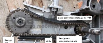
Fastening the camshaft sprocket (tightening torque 20 Nm).
Cylinder block (CB400N). 1 — coolant pipe mounting bolt, 2 — coolant pipe, 3 — o-ring seal, 4 — chain tensioner mounting bolt, 5 — chain tensioner, 6 — tensioner gasket, 7 — fastening bolt, 8 — cylinder, 9 — gasket, 10 -locating pin, 11 — lock ring, 12 — piston pin, 13 — piston, 14 — upper compression ring, 15 — lower compression ring, 16 — oil scraper ring.
Cylinder head (CB400N). 1 — coolant pipe mounting bolt, 2 — coolant pipe, 3 — cylinder head mounting bolt, 4 — cylinder head mounting nuts, 5 — cylinder head assembly, 6 — gasket, 7 — mounting sleeve, 8 — spacer carburetor
1 — nut securing the cylinder head. 1 — fastening nut, 2 — fastening bolt.
Cylinder head (CB400N). 1 • pusher, 2 — adjusting washer, 3 — crackers, 4 — spring plate, 5 — valve spring, 6 — inlet valve, 7 — exhaust valve, 8 — oil scraper cap, 9 — spring seat, 10 — valve guide.
Honda CB400F(CB1)
Camshafts (CB400F). 1 - heat shield, 2 - cylinder head cover bolt, 3 - washer, 4 - cylinder head cover, 5 - gasket, 6 - camshaft bearing cover bolt, 7 - camshaft bearing cover, 8 - locating pin, 9 — intake camshaft, 10 — exhaust camshaft, 11 — pin.
Cylinder head (removal and installation) (CB400F). 1 — washer, 2 — cylinder head mounting bolt, 3 — cylinder head, 4 — gasket, 5 — mounting sleeve, 6 — timing drive mechanism bolt, 7 — mounting sleeve, 8 — washer, 9 — timing drive mechanism, 10 — spacer.
Cylinder head (disassembly and assembly) (CB400F). 1 — pusher, 2 — adjusting washer, 3 — cotters, 4 — spring plate, 5 — valve spring, 6 — valve, 7 — oil scraper cap, 8 — spring seat, 9 — valve guide.
Cylinder block (CB400F). 1 - coolant pipe mounting bolts, 2 - coolant pipe, 3 - o-ring seal, 4 - cylinder head mounting bolt, 5 - cylinder, 6 - gasket, 7 - installation sleeve, 8 - retaining ring, 9 - piston pin, 10 - piston, 11 - upper compression ring, 12 - lower compression ring, 13 - oil scraper ring.
Removing and installing camshafts
1. When removing and installing camshafts, the alignment marks must be aligned as shown in the figure.
- - tags,
- - intake camshaft,
- - exhaust camshaft,
- - tags,
- — mark “T”,
- — installation mark on the crankcase cover.
2. The bolts securing the camshaft bearing covers are unscrewed and tightened evenly in 2-3 passes.
Tightening torque 12 Nm
1 - drive housing, 2 - driven gear, 3 - drive gear, 4 - intermediate gear, 4 - locating pin.
1 — installation sleeve, 2 - mounting bolts, 3 - installation sleeve.
Tightening the timing drive mounting bolts is carried out in the order shown in the figure.