Rear axle of a Ural motorcycle. We change the main pair.
Riding with an 8-wheel drive in the rear axle of a motorcycle did not bring satisfaction, especially since the rear wheel had a 16” rim.
The engine roars at maximum speed, and the speed barely reaches 90 km/h. It was decided to change the main pair in the rear axle of my Dnepr motorcycle. I had a stroller pair (8/37 with a ratio of 4.63), and at the market I bought an accelerated pair (10/35 with a ratio of 3.5). I expected the speed increase to be about 32%.
I started by draining the oil from the bridge by unscrewing the bottom plug. I took off the rear wheel, disconnected the brake rod, unscrewed the four nuts securing the bridge to the pendulum, pulled it slightly towards myself, and now I have the bridge in my hands. The brake pads were removed and put aside.
I unscrewed the protective cover (cap) of the hinge; note that it has a left-hand thread. Next, I unscrewed the nut and carefully, so as not to spoil the thread, knocked out the wedge bolt securing the hinge. Lightly tapping the body of the hinge mechanism with a hammer, he removed it from the drive gear shaft.
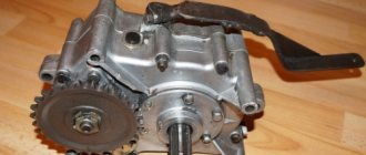
Unscrewed the six nuts securing the crankcase cover. Some nuts came off along with the studs. By quietly tapping the crankcase cover with a hammer, he disconnected the cover and the crankcase. When I pulled out the cover, needles from the needle bearing fell into the crankcase. I carefully counted them all (45 pieces) and collected them in one place.
To remove the large gear from the crankcase cover, I had to screw in two long bolts in place of the studs securing the crankcase to the pendulum and slowly use them to squeeze out the hub with the driven gear.
I immediately cleaned the threads in the crankcase cover with a sword. Removed the thrust bushing from the driven gear hub.
Next, I unscrewed the aluminum shank nut. It also turned out to have a left-hand thread.
Pulling the shaft, shaking it a little from side to side, he pulled it out of the crankcase. The needle bearing remains in the housing. I removed all the needles from the bearing cage, there were 28 of them.
Removed the collar seal from the crankcase cover.
I knocked out the support bearing (207) through the holes in the hub and loosened the 8 bolts securing the driven gear to the hub. The bolts were loosened and unscrewed almost by hand. Removed the driven gear.
I washed the crankcase body and cover in gasoline.
I started installing the new driven gear on the hub. It turned out that the old mounting bolts did not fit on the new gear. Different thread pitch. I had to look for eight suitable bolts.
To properly tighten the bolts securing the driven gear to the hub, I had to use a motorcycle wheel. By inserting the hub into the grooves, you can easily tighten the bolts to the desired torque.
Next, I locked the bolts and installed the support bearing in the hub.
The drive gear did not fit into the crankcase housing. The inner flange against which the double-row bearing rested was in the way. I ground off the excess metal so that there was a stop for the bearing, but nothing prevented the drive gear from rotating in the crankcase. The crankcase was washed again with gasoline and blown dry with compressed air to remove sawdust.
Having compared the thickness of the old and new drive gears along the shaft axis, I saw that the new one (10) turned out to be “fuller” than the old one (8) by 1.3 mm. I had to take it to a turner and cut off the excess metal from the side of the double-row bearing so that the bearing could fit closer to the teeth.
After grooving, I installed the inner race of the needle bearing on the drive shaft. Using a spark plug wrench, I installed the double row bearing in place.
I removed two old oil seals from the aluminum nut and installed new ones in their place, having first slightly lubricated the side surfaces with engine oil. The seals didn't want to come into place completely, so I had to carefully put them in place through a wooden spacer.
Having thickly smeared the outer race of the needle bearing in the crankcase with lithol, inserted all the needles there and aligned them with a finger in a circle.
Installed the drive shaft into the crankcase and tightened the aluminum nut. The shaft rotated easily on bearings. The gear teeth did not touch the housing. Using a gas wrench, I finally tightened the aluminum nut.
The cardan joint was installed as follows. First, I inserted the hinge onto the shaft and looked into the hole in the wedge bolt. The holes in the joint and on the shaft matched, and this was incorrect. When installed, the wedge bolt would fall completely into the hole.
Using adjusting washers, I ensured that the holes did not coincide, and the hole in the hinge body was slightly ahead of the hole on the shaft.
Next, I inserted a wedge bolt into the hole with the ground edge forward, towards the crosspiece, and hammered it there with a hammer so that the wedge would pull the hinge onto the shaft and the hinge would rest against the adjusting washers. A small part of the wedge remained sticking out outside; he could not go any further. If the wedge goes inside the hinge body, then you need to add shims. I managed to install as many as five washers. After that I tightened the wedge bolt nut. The drive gear was finished.
MY MOTORCYCLE
In a certain sense, the main gear of the Ural could be considered an eternal unit... However, no one is safe from breaking the teeth of the main gear gears. Most of these problems appear on motorcycles with sidecars, whose owners ignore the factory recommendations for load capacity. It’s the same with us: they load until the boat starts to crack. Especially models with a sidecar wheel drive, whose transmission often experiences increased loads when the sidecar wheel touches the road again after leaving it. And many owners of “Urals” and “Dneprs” have to repair broken “bridges”.
Our subsequent recommendations may also be of interest to those users who would like to replace the “sidecar” gears of the main gear with a “nine” gear for “singles” (the name comes from the number of teeth of the drive gear).
Make no mistake, this is not easy to do.
Cramming the gears and bearings into the crankcase isn't even half the job. The most difficult thing is to adjust the meshing of the gears and the gap between them. This procedure requires skill, time and patience. In any case, the Irbit Motor Plant ran out of patience (well, the Kiev “Dneprostroitelny” plant has long been covered with a copper basin), and, citing (this was a long time ago) achievements in the manufacture of “bridge” parts with increased accuracy, all adjusting washers were removed from the design. This “innovation” made production easier and cheaper, but, to put it mildly, did not increase reliability; rather, on the contrary. We can't help you here. Advice. When buying a new “pair” in a store as spare parts (if you can find any at all), pay attention to the fact that the gears are numbered with the same number (before heat treatment, the gears are rolled together in pairs and only then subjected to carburization).
Avoid purchasing goods of dubious origin! Along with the “pair”, buy a new collar seal. And prepare paint, preferably “nitra” (it dries faster), and a brush - you will paint the gear, the color is to your taste. When the preparations are completed, you can get to work:
1. Before disassembling the “bridge”, drain the oil from it. Unscrew the screws securing the collar seal cover and remove it together with the seal.
2. Unscrew the nuts and separate the crankcase cover along with the hub and driven gear. When you separate the cover, the hub bearing needles will begin to fall off the hub. Collect them and count them - there should be 45 pieces
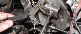
3. Take the rear wheel axle and insert it until it stops, as shown in photo 3. Apply several blows to the end of the axle with a hammer. The inertial forces of such a heavy part as a hub with a driven gear will force it to unpress from the bearing (pressed, in turn, onto the “bridge” cover) or together with the bearing from the cover.
4. If the hub ball bearing shows signs of wear, use a universal puller to press it off the crankcase cover. Or, if it “stayed” in the hub, push through the holes in the hub. And throw it away, and instead press a new bearing into the hub.
5. Take the wrench used to adjust the suspension spring preload and unscrew the pinion ball bearing nut (note: left-hand thread). Then remove the rubber ring-seal, the shaped washer and the pack of spacer washers (if you did not remove them earlier when removing the cardan fork from the splined part of the drive gear shank).
6. Now remove the drive gear with the double row ball bearing from the final drive housing. During this operation, the needle bearing needles of the shank may fall out of the outer race. Don't lose them.
7. The shank needle bearing practically does not wear out, and its inner race serves as a kind of “carrying pennant” for new drive gears. Try to remove (unpress) this clip with two powerful screws. If this doesn’t work, either grind off some of the teeth with sandpaper to grab the cage with a puller, or even cut off part of the shank with a grinder flush with the cage, and then knock out the unnecessary remnant of the winding gear from the cage.
8. Take the driveshaft yoke (or entire shaft assembly), new drive gear, double row bearing, spacers, and wedge bolt. Place the bearing on the gear, then the rings, the cardan fork and drive the wedge bolt. In this case, the inner race of the double-row ball bearing, consisting of two rings, will be “clamped” on one side by the shoulder of the shank, and on the other by the cardan fork. This happens due to the fact that one edge of the wedge is beveled (it should “look” forward as the motorcycle moves). When you hammer it in, the fork rides on the bearing, firmly fixing it to the drive gear. The thickness of the package of spacer washers is selected so that the wedge head protrudes a few millimeters above the surface of the fork, and the drive gear rotates easily in the bearing without jamming (but also without noticeable axial play).
Messages [1 to 20 of 47]
1↑ Topic by Gregory 08/14/2014 17:24:39
- Gregory
- Experienced
- Inactive
- Registered: 03-08-2014
- Messages: 366
- Reputation: 44
- Motorcycle: “Ural” IMZ-8.103-10
Topic: Which gearbox should I install?
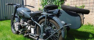
I know this is somewhat offtopic, but I didn’t find the “transmission” section. The point is this. Finally, my favorite “Russian Harley-Davidson” - IMZ-8.103-10 - came into my hands. Brutal device. Now I’m going through it and turning it into a Soviet retro-tourist chopper. Loner naturally. I took off the stroller. And immediately a problem arose. A gearbox, or rather the gear ratio of its bevel pair. For me it is 4.62 at the moment (eight), i.e. standard gearbox for wheelchair users. And I want to have the highest possible speed (36 hp engine). In addition to the eighth gearbox, there are also so-called. “ninth” (3.89) and “tenth” (3.3). I heard that people drove their Urals to
160km/h. So, armed with formulas and conventions of quantities, I sat down here to make smart calculations. As a result, it turns out that at maximum power speed (5600 rpm) and in fourth gear (1.3) with a standard rear wheel 4.00-19″ (tyre outer diameter 690 mm, circumference 2.167 m), the speed is as follows: - from 4.62 (eight) - 121.7 km/h . - from 3.89 (nine) - 140.3 km/h . - from 3.3 (ten) - 170.1 km/h . Thus, it is clear that the old eighth gearbox will have to be changed. But what is the problem? On the ninth or tenth? The fact is that I operated with the rotation speed at which the engine develops maximum power (5600 rpm), but I could not find data about the maximum permissible engine speed. By analogy with the engine of a VAZ car, I can assume that it is somewhere around the mark
6000rpm Torque of the engine is dangerous, especially since there is no tachometer on the motorcycle (according to style rules, it is not required). I'm lost in thought. On the one hand, logic dictates that it is necessary to put a “ten” because... with a pair of 3.89 it’s impossible to reach 160 km/h even theoretically. With a pair of 3.3 this is possible, but the top gear is too long, which does not correlate well with the modest engine power, is questionable. Although I plan to transfer the engine to AI-92 with the replacement of pistons, after which its power will increase to
40hp Please share the experience of people who know the topic. Otherwise, changing the gearbox a hundred times will be quite expensive.
Source
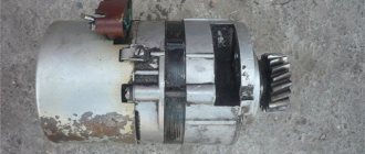
Information about the stages of modernization of axle gearboxes for 6x6 vehicles.
- 1984 – introduction of an additional bevel gear bearing (an angle was introduced to lubricate the bevel gear bearing and the gearbox configuration was changed).
- 1996 - two additional holes were introduced on the gearbox flange for mounting to the bridge Ø 19 mm and the diameters of 7 (seven) holes were increased from Ø 15 mm to Ø 17 mm.
- 1999 – the material of the adjusting nut 375-2403040 was changed instead of KCh and is made of 35L steel.
- 2001 – a locking plate for fixing the differential nut 375-2403042 was introduced, increasing the size of the locking part from 46 mm to 51 mm.
- Since 2003 A gearbox with a fixed side cover and a square is offered as spare parts (for example, a gearbox with i = 7.32:
- 4320-2302007 – front axle gearbox
- 4320-2402007/2502007 – rear/middle axle gearbox)
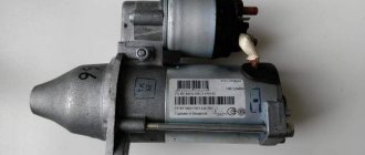
The gearbox is supplied unpainted and preserved for spare parts. The serial production number and production date are stamped on the gearbox housing flange. A plate with the gear ratio and car model stamped on it should be installed under the cup cover bolt 375-2402135.
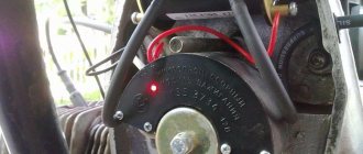
OWNERS OF URAL MOTORCYCLES OFTEN FACE THE PROBLEM OF OIL LEAKING FROM THE MAIN TRANSMISSION CASE. WHAT TO DO?
To eliminate oil leakage, it is most likely necessary to replace the collar seal. Using a screwdriver, remove the oil seal cover. Then, unscrewing the fastening screws, remove the oil seal itself. Next, you need to put a new oil seal on the hub so that the spring does not come off. Place the oil seal onto the spline portion of the driven gear hub, and then insert a match into each spline and install the oil seal in place. Attention! The oil seal must be oriented so that the technological hole in it coincides with the oil drainage channel in the axle housing.
WHILE DRIVING, THE FINAL DRIVE CASE HEATS. OIL LEVEL IS NORMAL. WHAT CAUSES THIS?
Heating of the final drive of heavy motorcycles is normal and occurs even in the presence of oil. The greater the load on the motorcycle, the more the “bridge” heats up. Heating the oil to 70°C is considered acceptable. Exceeding this value indicates either a lack of oil in the main gear, or incorrect assembly, or a malfunction inside the axle.
WHEN DISASSEMBLYING THE MAIN DRIVE, THE HUB BEARING ROLLERS ARE SOMETIMES LOST. HOW TO MAKE A ROLLER YOURSELF?
The lost roller will be replaced by a homemade one from the tail of a drill with a diameter of 3 mm. It is necessary to cut off a part of the drill 15.9 mm long and process it on low-abrasive paper to size 15.81
IS IT POSSIBLE TO CHANGE THE METHOD OF MOUNTING THE MAIN DRIVE?
If, due to untimely tightening of the nuts on the pendulum, the holes for the fastening studs are broken, then you can secure the main gear using the principle of installing wheels on a car. To do this, you need to make cone-type fastening nuts. Using a drill with a diameter of 15 mm (with a sharpening angle equal to the angle of the nut cone), drill holes in the pendulum to a depth of 5 mm. This type of fastening does not require any tightening.
WHAT TO DO IF THE SEALING OF THE STUDS SECURING THE MAIN TRANSMISSION CASE IS LOOSEN?
You can do this. Make through holes in the crankcase, cut M8 threads into them, and install bolts. Secure the final drive housing with nuts. To prevent the bolts from turning, their heads must be connected in pairs with plates, and the edges of the plates must be bent. The crankcase is now securely secured.
HOW TO MAKE THE MAIN TRANSMISSION SHAFT SEAL FOR MOTORCYCLES “URAL”, “DNEPR”
If you don’t have the required main gear shaft oil seal on hand, you can make it yourself. Cut a washer with an internal hole of 40 mm from a sheet of oil-resistant rubber 3-4 mm thick. Place it on the main gear hub and use a screwdriver to thread the resulting collar. Such an oil seal can last quite a long time.
content .. 41 42 47 ..
Information information on the stages of modernization of drive axles of 6x6 vehicles.
- In 1987, two additional mounting holes for the swing arms and pivot bearing caps were introduced (there were 4 mounting points, now there are 6 points).
- In 1996, the wheel steering adjustment bolts were canceled and milled platforms (plates) were introduced.
- In 1996, in connection with the transfer of the power steering from the right side of the car frame to the left, the levers on the steering knuckles of the front axle were changed (a cover was installed on the right steering knuckle, and a double-headed lever was installed on the left steering knuckle). This year:
- the diameter of the lever mounting studs and the steering knuckle cover has been increased from M16 to M18 (the diameter of the expansion bushings has also increased accordingly);
- the strength class of the studs securing the ball joint flange to the axle housing was raised from 8.8 to 10.9, the strength class of the nut from 6 to 10 and, accordingly, the tightening torque of the nuts securing the ball joints to the axle housing increased from 16-20 to 28-32 kgf*m.
- The diameter of the studs for fastening the rotary axle has been increased from M14 to M16.
- In connection with the introduction of a press fit of the ball joint flange into the axle housing, the length (increased from 55 to 85 mm) and diameter of the ball joint journal changed, and the diameter of the hole in the axle housings changed.
- In 1999, brake drums were installed, with turning along the outer diameter.
- In 2003, a reinforced front axle
, with the following changes made: - of housing
has been changed, and the filling capacity has increased from 5 to 8 liters; - the diameter of the axle housing
(a 121x22 mm pipe has been replaced by a 133x30 mm pipe); - the fastening of the ball joint
to the axle housing has been strengthened (the number has been increased from 8 to 11 and the location of the mounting holes has been increased from Ø 143 to Ø 160 mm, the flange diameter has been increased from Ø 176 to Ø 190 mm); - shock absorber bracket
has been changed ; - in the steering knuckle body,
the location of the rotation limit plate has been changed, the number of threaded holes for attaching the axle has been increased from 8 to 12; - the dimensions of the conical holes in the body and the
steering knuckle lever for the reinforced hinge pin have been increased from 28 to 30.25 mm; - in the steering axle,
the number of mounting holes to the steering knuckle has been increased from 8 to 12; - The front spring mounting clamps
were replaced with clamps for an increased casing diameter; - a reinforced CV joint
and modified axle shafts (outer and inner) are installed on the front axle - The sealing collar is moved from the cavity of the axle housing
to the steering knuckle mounting flange in the axle housing. - In 2003, a cast brake caliper
instead of a stamped one. - The factory production number of the front axle and the date of manufacture are applied to the axle housing, to the right along the direction of the vehicle.
For spare parts, we offer, for example, front axle 4320-2300010-24 (with gear ratio i = 7.32, reinforced):
For ordering spare parts and installing a reinforced front axle on vehicles produced before 2003
There is a set
4320Х-2300012-10
consisting of:
- 4320-2300010-24 front axle – 1 pc.
- 6361-2301025 clamp – 1 pc.
- 6361-2301042 clamp – 1 pc.
- 6361-2905130 shock absorber pin nut – 2 pcs.
- 5557-2905410 shock absorber bushing – 4 pcs.
- 4320-3414065 finger – 2 pcs.
- 336448 washer – 2 pcs.
- 334933-P29 nut M22x1.5 – 2 pcs.
- In 1995, a reinforced axle housing was introduced (the filling capacity was increased from 5 to 8 liters).
- In 1999, brake drums were introduced, with turning along the outer diameter.
- In 2003, a cast brake caliper was introduced instead of a stamped one.
- The factory production number of the rear (middle) axle and the date of manufacture are applied to the axle housing, to the right along the direction of the vehicle.
For spare parts, for example, axles with i = 7.32 are offered:
- 4320-2400010-20 – rear axle
- 4320-2500010-20 – middle bridge
Speedometer drive gears
| Gear ratio of the main drive of the drive axle | Designation and name of the speedometer gear | Number of teeth | Outer diameter, mm |
| 6,7 | 4320Я-3802033 Drive gear (on the intermediate shaft) | 6 | 67,27 |
| 4320Я-3802035 Driven gear (in the cover) | 22 | 30,19 | |
| 7,32 | 4320-3802033 Drive gear | 5 | 69,85 |
| 4320-3802035-10 Driven gear | 20 | 27,60 | |
| 8,05 | 43202-3802033 Drive gear | 5 | 67,33 |
| 43202-3802035-10 Driven gear | 22 | 30,13 | |
| 8,05 | 5557-3802033 Drive gear | 5 | 64,82 |
| 5557-3802035 Driven gear | 24 | 32,65 | |
| 8,9 | 375-3802033-B Drive gear | 5 | 62,29 |
| 375-3802035-01 Driven gear | 25 | 35,17 |
Nomenclature and gear ratios
of gearboxes for Ural vehicles for ordering spare parts.
| Gear ratio | Gearbox part number | Name | Number of teeth in driven cylinder. gears |
| 1 | 2 | 3 | 4 |
| 6,7 | 4320Я-2302007 4320Я-2402007 4320Я-2502007 | Front axle gearbox Rear axle gearbox Middle axle gearbox | 46 |
| 6,7 | 4320Я-2302007 43206-2402010 | Front axle gearbox Rear axle gearbox | 46 |
| 7,32 | 4320-2302007 4320-2402007 4320-2502007 | Front axle gearbox Rear axle gearbox Middle axle gearbox | 47 |
| 1 | 2 | 3 | 4 |
| 7,32 | 4320-2302010-10 | Front 1st axle gearbox | 47 |
| 5423-2322010 | Front 2nd axle gearbox | ||
| 5423-2402010 | Rear axle gearbox | ||
| 4320-2502010-20 | Middle axle gearbox | ||
| 8,05 | 5557-2302010 | Front 1st axle gearbox | 48 |
| 5423Х-2322010 | Front 2nd axle gearbox | ||
| 43223-2402010 | Rear axle gearbox | ||
| 5557-2502010 | Middle axle gearbox | ||
| 8,05 | 5557-2302007 | Front axle gearbox | 48 |
| 5557-2402007 | Rear axle gearbox | ||
| 5557-2502007 | Middle axle gearbox | ||
| 8,9 | 4420-2302007 | Front gearbox bridge | 49 |
| 4420-2402007 | Rear gearbox bridge | ||
| 4420-2502007 | Middle axle gearbox |