WHY DO YOU NEED A VOS REGULATOR ON A MICROCONTROLLER
Despite the widespread use of injection (injection) engines, where the preparation of the fuel mixture and ignition timing are controlled electronically, carburetor engines with a mechanical ignition timing regulator will probably be in operation for a long time.
As is known, the power developed by the engine largely depends on how much the ignition timing formed by the centrifugal and vacuum regulators corresponds to the optimal timing. Tyufyakov A., author of the work “Ignition System without Secrets” (Collection Avtomobilist-86. - M.: DOSAAF, 1986), believes that even with normal operation of the centrifugal regulator, the engine loses 5-10% of power due to the fact that The characteristics of the centrifugal regulator do not correspond to the optimal one. In reality, these losses are much greater, since it is also necessary to take into account:
· various backlashes in the drive of the sensor-distributor (distributor);
· wear of the bearing on which the breaker is mounted (or the Hall sensor in the non-contact version of the ignition system);
· change in the elasticity of the springs of the centrifugal regulator during operation, its inertia, etc.;
· the main thing is that it is impossible, using a simple mechanical device, to reproduce the SOP dependence curve, first along the detonation boundary (up to 2800 rpm), and then along the optimal SOP curve, i.e., to ensure its best performance.
In this regard, an ignition unit was developed - an ignition timing regulator on a microcontroller.
Using an ignition timing regulator on a microcontroller allows you to:
· reduce engine power losses, increase power at low speeds;
· improve engine acceleration dynamics;
· reduce fuel consumption;
· achieve more “smooth” engine operation;
· improve engine starting through the use of multi-spark starting.
The ignition unit - ignition timing regulator - is designed to replace the standard centrifugal and vacuum regulator of VAZ 2101–2107 engines with an electronic analogue made on the PIC12F675 microcontroller. In addition to VAZ 2101–2107, the device (in different versions) was successfully used on carburetor engines VAZ 21213 (Niva), VAZ 2109, GAZ-21 (uprated, AI-92), Toyota Corolla (1988, 2E engine volume 1.3 cubic dm.), MAZDA-323, etc.
The device forms the OZ angle in accordance with Figure 1 (refined characteristics for the VAZ 2103 engine - in the figure there are only 5 OZ graphs out of 32 possible).
Rice. 1. Refined characteristics of the formation of SOP.
The new feature described and applied in this article further improved the vehicle's dynamics compared to previous versions of the program previously reported in other sources.
help with Saruman, I have no more strength(((
I bought a Saruman ignition kit in the Urals here https://vk.com/fuoz_saruman, connected it, it works intermittently, stalls, shoots, sneezes, does everything except smooth engine operation, I remove the fuoz engine whispers. Naturally I’m sinning on it. I’m sending it under warranty back, the verdict is that it is OK. I put it on again, the result is the same. I order another Fuoz unit here, https://vk.com/mega_bsz, I wait for it to arrive. I connect it in anticipation of a miracle, I start it - the result is the same as with the previous one. I set the ignition as follows: I set it to TDC according to the risk (I even removed the head to make sure that the risk corresponds to TDC), when the modulator comes out of the optical sensor, I fix it. At the same time, the light on the sensor lights up, and goes out at fuoz as written in the instructions. Why does the engine whisper without it, but doesn’t want to with it? coil from Oka/Gazelle, VAZ switch (I’ve already changed several pieces) if you have any sensible thoughts, please share, don’t leave them in the lurch like the sellers of these fuozes do. Thank you in advance))))
- Login or Register
what spark plug wires are there?
- Login or Register
silicone, from snowstorm (blue)
- Login or Register
Sarumanka works great without silicone. At least it worked for me with regular wires. Also works great with a standard reel. take the sarumanka from the cap. it has a factory version. The quality is agonizing! And it’s disgusting to pick up all these cheap student crafts after disassembling them, even though the links don’t open.
- Login or Register
I'll fix the links now.
- Login or Register
The lighter is placed not according to TDC, but according to the ignition mark... it is located in front of TDC.
- Login or Register
Ural '91, I have only one mark on the flywheel and it corresponds to TDC, not reaching it how many mm should it be?
- Login or Register
The flywheel is about 18mm short of TDC.
- Login or Register
search the forum. if the memory doesn’t change, then 9mm seems to be short of TDC
- Login or Register
TS, CAREFULLY read all the information on installation and configuration on the website of the author of the ignition. For the especially lazy: “The LED turns on when the active element of the modulator (lobe or cutout) enters the Hall sensor and goes off when it exits. During the initial adjustment for boxer engines, the moment the shutter leaves the sensor (and, accordingly, the LED turns off) should approximately coincide with TDC; it is at this moment that sparking will occur at starting speed.”
Brainwashing often occurs if the firmware is a cutout, but the modulator is actually a petal, or vice versa.
Тeddy, the Sarumanka is placed precisely at TDC. —————————————————— Everything you need is simple. Everything complicated is not necessary.
- Login or Register
What is the difference between setting the start of sparking on a Saruman and an Uktus or any other ignition? I’m aligning Saruman with MH, TDC will be later.
- Login or Register
- Login or Register
Another idea is to make sure that the sensor and the switch are working, that is, exclude the FUOZ unit itself, and connect the output of the sensor to the input of the switch. Yes, and you did not indicate the type of motor and the voltage of the on-board network - 6 or 12 volts. —————————————————— Everything you need is simple. Everything complicated is not necessary.
- Login or Register
Thanks for the site, interesting information. I wrote that after removing the fuoz, the engine works perfectly, picks up speed, drives, runs smoothly. I put the fuoz on and that’s it. motor normal stock 649 cc, 12 volts, VAZ regulator relay, outputs
- Login or Register
- Login or Register
That's it, I just found out from you.
- Login or Register
There was a similar problem - with the butterfly modulator, the motor started working - at the moment of initial setting of the maximum advance angle - 36 degrees to TDC.
- Login or Register
To hell with these marks. I always set them by ear. Then sometimes I corrected the ignition angle based on the dynamics of acceleration. For example, on my Wolf, according to the marks, the motorcycle stalled and the potassium sometimes skipped. I did it later and everything became ok.
- Login or Register
Hi all ! I’m just starting to disassemble electronics and don’t really know much, right now I also have small problems with Saruman, everything works fine without load, cutoff, etc. — everything is ok (I installed it recently and rode only once) but as soon as I drove near the garages not far and slowly, Saruman refused, there was a signal to him, but not from him, I drove 50m to the garage, turned on the ignition and started without problems , I drove off again, got to the same place (you have to turn around there), stalled again - the same thing, again to the garage, turned on the ignition and started it again. In general, I didn’t ride anymore because the kickstarter started slipping (tomorrow, if I succeed, I’ll remove the gearbox). I have a homemade injector on a 555 chip, and as a result of very long settings and debugging, I noticed this (by the way, I have a homemade optocoupler with 2 transistors) the signal from the optocoupler does not have the same voltage thresholds depending on the speed, I had during installation electronic ignition 2108 there was always an LED on the signal wire with the OP (everything worked OK), so - I take this signal and shove it into the injector board on the 555, the injector is triggered at the input and at the output of the curtain (not correct) and somehow by accident I I unhooked the LED and noticed that the injection was only at the output of the curtain as it should be, that is, there was some tiny change in voltage and it began to work differently, or maybe there was some kind of filtration - I don’t know, then I figured it out and the injector did not I began to feel whether there was an LED or not. then I installed the Saruman and this is what I noticed - without this LED there is a spark, it works at idle, but if you give it gas it starts to sneeze, shoot, triple - it doesn’t work, although with all this the LED on the Saruman blinks regularly, then I connect this LED and the engine is replaced - It works smoothly at all speeds, which is what this LED gives, I still can’t figure out whether it’s reducing the signal voltage, or something else, but right now I can’t figure it out completely and will have to drive with this LED. This is such crap.
- Login or Register
ADDITIONAL PROGRAM FUNCTIONS
In addition to the above-described regulation of the ignition timing, the program has a number of additional functions that somehow improve engine performance.
Optimization of spark formation.
The program has a function to turn off the coil - if there is a constant low level at the input of the GP5 controller, after 2-3 seconds the output of GP1 is set to a high level. If GP5 is constantly high, the program generates multi-spark trigger pulses (see below).
In the range from 370 to 2000 rpm. the program generates an accumulation time of 12 ms; in the range above 2000 rpm. – maximum possible accumulation time. This allows you to obtain spark energy sufficient to reliably ignite the mixture in all engine operating modes and use the B117A ignition coil more efficiently. The heating of the coil at low speeds is reduced, and maximum speeds are easily achieved regardless of the gap in the breaker contacts.
Multi-spark start.
In the range from 0 to 370 rpm. Instead of one ignition pulse, the program generates a series of pulses with the following parameters: 2.3 ms is allocated for the spark, 12 ms for energy accumulation in the coil. The slower the starter rotates the crankshaft flywheel (CF), the more sparks occur each time the breaker contacts open (high level at the GP5 input). Multi-spark starting guarantees engine starting in severe frost, carbon deposits on spark plugs and flooded spark plugs.
Adjustment of OZ.
This version uses an additional ADC channel AN0, which can be used to shift the SCR by ±10 degrees relative to the original characteristic (Fig. 1).
The correction value is set by potentiometer R4. Instead of R4, in practice it is more convenient to use a switchable voltage divider. When the voltage at input AN0 changes from 0 to +5 V, the graph in Fig. 1 is shifted from –10 to +10 degrees relative to the original. At a voltage equal to 1/2 the microcontroller supply voltage (+2.3 V), the graph corresponds to Fig. 1. This channel can be used to regulate the SOP on a cold and warm engine - control from the choke button. Potentiometer R1 shifts the OZ by +5 degrees when the “suction” is extended on a cold engine (after setting R1, it is better to replace it with two constant resistors). Potentiometer R2 allows you to adjust the SOP manually with the air damper fully open (on a warm engine). The dependence of the voltage on the potentiometer sliders on the angle of rotation is nonlinear. R2 is located inside the car, which allows you to adjust the OZ on the go.
Maintaining XX speed.
This version of the program has a function for maintaining idle speed (idle speed) 930 rpm. To do this, on a warm engine (the headlights must be on), use the carburetor adjustments to set the speed to XX 900–930 rpm. When the idle speed deviates from 930 rpm. the program changes the SOP in the range from 7 to 14 degrees, setting the KV speed to 930 rpm. (correction along the AN0 channel is also taken into account and added to the range of 7–14 degrees). In practice, after appropriate adjustment, the speed remains constant when turning on/off the high beam headlights, heated glass and other consumers combined. Previously, you can turn off the “choke” when the engine warms up. You can get stable idle speeds with a lean fuel mixture. On a flat road, the engine “pulls” without jerking or jerking when the gas pedal is released in 1st, 2nd, 3rd and for a short time in 4th gear (this makes it easier to drive in icy conditions, in traffic jams, when driving over bumps - “riding tight”).
Adjustment for vacuum sensor.
The program has a function for automatically adjusting to the range of vacuum changes in the engine intake manifold, which simplifies the setup of a homemade vacuum sensor, and also allows you to use an industrial absolute pressure sensor (DAP 45.3829). The program independently determines the type of discharge sensor (by the maximum voltage at input AN2), therefore, in order not to mislead the program, do not configure the homemade sensor for a voltage greater than 2.3 V.
When using a homemade inductive vacuum sensor, the setting is reduced to setting the maximum voltage at the ADC input in the absence of vacuum and the minimum voltage at maximum vacuum (Fig. 2). To ensure greater accuracy in the formation of the SPD (in accordance with Fig. 1), the inductive sensor should be configured so that the maximum voltage at the ADC input is from 1.5 to 2.3 V, and the minimum is equal to or less than 0.9 V.
Rice. 2. Setting up a homemade inductive vacuum sensor.
The sensor is configured by selecting C3 and R10 before installing the unit on the car. Vacuum is simulated by moving the rod of the vacuum chamber from one extreme position to another.
APPLICATION WITH CONTACTLESS IGNITION SYSTEM
This version of the program can be used to work with a contactless ignition system (instead of a breaker - a Hall sensor). The OZ angle former is assembled according to the diagram in Fig. 4a (for ignition coil 27.3705) or Fig. 4b (for coil B117A). If necessary, you can use a homemade inductive vacuum sensor (connected in the same way as in Fig. 3).
Rice. 4a. Device diagram for a contactless ignition system (coil 27.3705).
Rice. 4b. Device diagram for a contactless ignition system (coil B117A).
The operation of the driver was tested on VAZ 2109 and VAZ 21213 (Niva) cars.
FUOZ Saruman. Help needed!.
This system has been considered outdated for almost half a century. Motorcycle owners often complain about oxidizing and burning contacts, the formation of an oil film, and the need to constantly clean and reconfigure the ignition system. Of course, inquisitive minds have already found a solution to this problem, so installing electronic ignition on the Ural is currently not something extraordinary.
Electronic ignition for the Ural motorcycle is now produced by several companies. The most common models are the SoveK microprocessor contactless ignition system, the Saruman ignition system, the Stary Oskol ignition system and the UKTUS-2 microprocessor ignition. Unfortunately, the last two systems are quite outdated, although they are still popular. In addition, there are a huge number of options for homemade systems. Many owners of motorcycles of this brand make their own ignition for the Ural. Electronic (or contactless) is superior in all respects to the old mechanical model, whose adherents remain only those who support the postulate “the older, the better.”
Saruman ignition to the Urals
One of the main pain points of heavy Ural motorcycles is the ignition system. Although currently motorcycles produced by IMZ are equipped with Italian-made Ducati Energia electronic ignition, only about three percent of the bikes produced today are sold in the Russian Federation. Most of the owners travel across the country using outdated mechanical ignition in the Ural. Electronic one has a number of advantages.
MBSZ "SoveK"
Sovek LLC has developed and successfully implements a microprocessor-based contactless ignition system for heavy Ural-type motorcycles. This option is suitable for those who do not want to bother with homemade units. The manufacturer promises improved starting in cold weather, increased engine stability by reducing spark asynchrony and optimizing the ignition timing, reducing exhaust toxicity, fuel consumption, stable starting even when the battery is discharged to a voltage of 6 volts, as well as preventing overheating of the ignition coil, which was one of the main problems of old systems. The main components are a modulator and a Hall sensor. Installing the SoveK ignition is quite simple, described in detail in the instructions and will take no more than half an hour.
Electronic ignition "Saruman"
The Saruman microprocessor ignition system is another way to quickly and without much hassle replace the outdated contact ignition of the Ural. Manufacturers promise the same set of advantages as the previous system. There are two configuration options: with a Hall sensor and with an optical sensor. The second option is somewhat more expensive, but it is usually recommended, since the optical sensor is more accurate and reliable. However, reviews from motorcycle owners are not as good as we would like, mostly complaints are made about the quality of assembly of parts. Another complaint is that the kit does not include an ignition coil.
Saruman ignition to the Urals
Ignition is possible in several options:
Small set: - switch (VAZ-2108) - advance board - Instructions Cost: 1200 rub.
Average ignition kit: - switch (VAZ-2108) - advance board - Hall sensor - wires, with connectors - Instructions - Shutter (Ural, Dnepr) - Mounting plate for the Hall sensor Cost: 2500 rub.
IMPORTANT DIFFERENCE FROM PREVIOUS VERSIONS OF THE PROGRAM
Below is a table for generating the key closing time. The red color in the table indicates the accumulation time, which is insufficient for reliable ignition of the mixture. Under “MK is not normal.” implies the accumulation time generated by versions of programs from QRZ.RU (03.2008) and FTP of the Radio magazine (11.2008).
Effect of key closure time formation.
The table shows that older versions with a breaker as a TDC sensor and a B117A coil can form a spark with sufficient energy only at a Closed State Angle (USA) of the breaker contacts equal to 65 degrees.
INSTALLING THE DEVICE ON A CAR
When installing the device on a car, the operation of the centrifugal and vacuum regulators is blocked: the weights of the centrifugal regulator must be secured using wire brackets instead of standard springs. The bearing race, on which the contact group of the breaker or the Hall sensor in the non-contact version is attached, is fixed with a metal plate connecting the race pin and the distributor body. The vacuum sampling hose for the OP angle regulator on the microcontroller is connected to the vacuum sampling pipe on the carburetor or intake manifold.
Any option can be used in a simplified form, i.e. without adjustment for vacuum. The standard vacuum regulator is not blocked in this case; input AN2 is connected to +5 V through a 10 kOhm resistor. The efficiency of the device in a simplified version will decrease. If input AN0 is not used, it must be supplied with a voltage equal to 1/2 of the microcontroller power supply (+2.3 V) from the divider through a 10 kOhm resistor.
The gap between the breaker contacts is set to the minimum possible (to reduce wear on the breaker cam), but ensures clear opening and closing of the contacts. After this, the initial angle of OZ is set: it must be equal to zero in relation to TDC and set according to the marks on the crankshaft pulley and the cylinder block when the engine is not running.
The transition to a microcontroller-based ignition system can be done in stages.
You first need to outline these stages for yourself, so that later there will be fewer alterations to the circuit.
· First, the block is assembled according to the diagram in Fig. 3 (for contact ignition system) or according to Fig. 4a/4b (for contactless ignition system). Unused ADC inputs are disabled (see above).
· Then the board is installed on the car, while the weights of the CR distributor are fixed. That's it, you can ride for your pleasure!
· If in the future you are going to connect a homemade vacuum sensor, use a slightly larger case in order to then place the sensor in it (if you plan to connect the DBP 45.3829, install a 5-volt stabilizer in the circuit to power the DBP, preferably on a zener diode and a resistor - like this more reliable).
The figure below shows an example of the design of an ignition unit with a homemade vacuum sensor
Of course, you shouldn't expect miracles from this device. “Zhiguli” will not turn into “Ferrari”, but they will drive very decently and at the same time consume noticeably less gasoline.
It is assumed that the engine is in good condition, the carburetor is adjusted in accordance with factory requirements.
If you fail to replicate the device, do not scold the author of the article and his program: read the text on the page carefully and you will find the reason for the failure.
The author does not recommend making changes to the circuits: apart from deteriorating performance and reliability (and sometimes complete inoperability), nothing will be achieved (this is especially true when replacing KS147 with 7805 or EH5). External devices (homemade tachometer) should be connected to the microcontroller ports via 3–10 kOhm resistors, and the resistors should be located on the board of the ignition unit - driver (the driver will work even if the tachometer connecting wires are shorted to the case). You cannot leave programmed but unused microcontroller inputs “in the air” (i.e., unconnected).
Optional.
It is possible to significantly reduce the error in the formation of the SPD at low speeds by installing a TDC sensor on the crankshaft pulley. Two options for implementing this option are discussed in the original author's article. Their implementation is quite labor-intensive and is not necessary when using a controller on a microcontroller, so they are not presented here. Those interested can familiarize themselves with them.
Description of the lot
MPSZ ignition Saruman for the Ural motorcycle.
Bought from the VK group “FUOZ BSZ SARUMAN Factory made ORIGINAL”, from Sayga Surax.
Kit - wiring, switch, curtain, opto-sensor.
Firmware - “warming up the spark plugs + cut-off at 4 thousand”.
It didn't work properly for me. Correspondence to the author and the implementation of his advice did not have any positive effect.
Perhaps it’s my crooked hands + my crooked Ural.
The problem is chaotic failures of one or the other spark plug (the spark plugs were changed 5 times, from imported NGK and Denso, to A11 and A14. Yes, I know that the ignition system in the Urals with a “idle” spark, that is, both spark plugs at the same time, but nevertheless, the spark spontaneously and chaotically disappeared on one or the second cylinder, both with new and old spark plugs). What was done according to the advice of the author of the ignition - charging the battery to “13.8”, checking the massplus (I threw it directly separately), replacing the coil (changed it to OKUshnaya). No positive results. Either it works normally, or it barely starts and runs on one cylinder.
“I freaked out,” I went and bought a microprocessor-based Sovek, installed it, and it started from the very first leg, it worked smoothly, stably, and the spark never disappeared.
So Saruman, whoever wishes, can acquire it. Maybe someone has straighter hands and everything will work out =)
MICROCONTROLLER FIRMWARE AND PRINTED BOARD
Printed circuit board
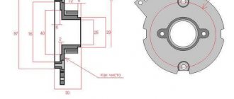
(pictures on the right) is universal and suitable for the manufacture of any version of the device. The elements are installed depending on the application. The board is designed to use SMD resistors, but if necessary, you can use MLT-0.125 resistors.
All parts are located on the conductor side; the foil on the opposite side of the board serves as a common wire and screen. Holes are drilled at the points where the leads of the parts connect to the common wire. The KT898A transistor is fixed to the radiator (metal casing) through a mica or fluoroplastic gasket.
Firmware check
in simulators it’s a waste of time, they (simulators) won’t tell you anything smart. If you want to make sure it works, check it on a breadboard using a two-channel oscilloscope and a PIC generator. Without instruments, the functionality of the microcontroller ignition system can be checked as follows: connect a spark plug to the high-voltage wire of the coil, open the breaker contacts (Fig. 3) and turn on the ignition. The program will operate in multi-spark start mode. For the circuit Fig. 4a, Fig. 4b, turn off the sensor and short-circuit the driver input to ground (the MK input cannot be connected directly to ground - it is possible that at this moment it is configured as an output, and this can damage the microcontroller). This mode can be used for burning carbon deposits and drying spark plugs, but, as a rule, with the multi-spark starting function there is no need for this - the engine starts reliably even with heavy carbon deposits on the spark plugs and with flooded spark plugs.
Download PCB drawing: F675OK.BAK
Download firmware for PIC12F675: F675OK.HEX
You can purchase a blank PIC12F675 controller at a retail outlet. You can flash a program into a microcontroller using an industrial or home-made programmer device, independently or to order.
ATTENTION! From us you can purchase a PIC12F675 microcontroller with the F675OK.HEX program already flashed at a fixed price of 250 rubles!
When ordering more than 5 pieces, the price is reduced.
Note. We do not sell this software. We provide services for firmware and supply of microcircuits. The program is distributed free of charge with the permission of the author.
