Honda dio 27 starter connection diagram
Scooter diagram a selection of eight diagrams of different models HONDA Dio AF18 AF27 AF28 SK50MJ
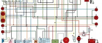
electrical diagram of Honda Dio Honda (
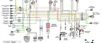
Dio SK 50 Mj ). 1 - brake light switch, 2 - starter switch, 3 - light switch, 4 - ignition switch, 5 - starter relay, 6 - battery, 7 - voltage regulator (rectifier), 8 - fuel level sensor, 9 - level sensor oil, 10 — right-rear turn signal, 11 — brake light and tail light, 12 — left rear turn signal, 13 — spark plug, 14 — breaker (CDI unit), 15 — starting enrichment, 16 — generator ,
17 — electric starter, 18 — resistor, 19 — horn, 20 — headlight switch, 21 — turn signal switch, 22 — horn switch, 23 — turn signal relay, 24 — left front turn signal, 25 — headlight, 26 — right front turn signal, 27 — instrument cluster, 28 — backlight lamp, 29 — fuel level indicator, 30 — oil level warning lamp, 31 — overspeed warning lamp, 32 — 7A fuse, 33 — ignition coil.
You can see the rest of the scooter elements here:
Source
Honda dio generator pinout
Scooter diagram a selection of eight diagrams of different models HONDA Dio AF18 AF27 AF28 SK50MJ
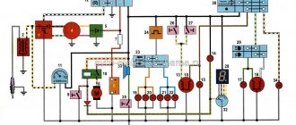
electrical diagram of Honda Dio Honda (
Dio SK 50 Mj ). 1 - brake light switch, 2 - starter switch, 3 - light switch, 4 - ignition switch, 5 - starter relay, 6 - battery, 7 - voltage regulator (rectifier), 8 - fuel level sensor, 9 - level sensor oil, 10 — right-rear turn signal, 11 — brake light and tail light, 12 — left rear turn signal, 13 — spark plug, 14 — breaker (CDI unit), 15 — starting enrichment, 16 — generator ,
17 — electric starter, 18 — resistor, 19 — horn, 20 — headlight switch, 21 — turn signal switch, 22 — horn switch, 23 — turn signal relay, 24 — left front turn signal, 25 — headlight, 26 — right front turn signal, 27 — instrument cluster, 28 — backlight lamp, 29 — fuel level indicator, 30 — oil level warning lamp, 31 — overspeed warning lamp, 32 — 7A fuse, 33 — ignition coil.
You can see the rest of the scooter elements here:
Source
Checking the regulator-rectifier and voltage generator
Disconnect the battery. We switch the device to 10 A. We put the red probe on the c/h wire, and the second probe on the minus wire - the green wire. Turn on the ignition. We pull the kickstarter leg. The device can show 5 - 10 A. This means that the voltage generator, regulator-rectifier, electrical wiring and fuses in the circuit from the generator to the battery are working.
If all this works, but there is no spark, then all that remains is to check the switch. It cannot be disassembled and has a complex electronic circuit inside. Therefore, it can only be tested on another similar working scooter. Finding a Japanese switch can be difficult. But there are many Chinese analogues, they work no worse than the original ones.
This troubleshooting sequence - no spark on dio 34, can be used on any 2t or 4t scooter or moped. All you need is an electrical circuit for the scooter, a universal set of screwdrivers and wrenches, and a multimeter (tseshka).
Those who are interested will be able to find the problem with the spark on their scooter or moped and fix it with their own hands.
If you have any questions, write. We'll figure out.
No spark on dio 34. Part 2: checking the coil, generator, switch
We continue the topic: there is no spark on dio 34.
We figured out the ignition switch using a multimeter. And now let’s move on to less common malfunctions and breakdowns in the electrical wiring of any 2t scooter from a Japanese or Chinese manufacturer. Be it a Honda Dio 34, 18, 27, 35, tact or older tacty, Suzuki, Yamaha. Of course, you are familiar with the situation: the scooter will not start. The spark is gone. What to do?
Checking the ignition coil
Disconnect the battery and remove the beak on the scooter. We disconnect the connector on the switch and measure the resistance on the coil with a meter. We put one probe in the connector on the black wire, and the second on the negative (green wire). There should be 4 ohms - this means that the wiring and the primary winding of the coil are working properly.
We check the second winding of the coil. We take out the probe from the contact of the green wire and insert it into the candlestick instead of the candle. And we leave the other probe on the contact of the h/w wire. The resistance should be about 7.85 kOhm. This indicates that the second winding, the armored wire and the candlestick itself are in good working order.
Let me remind you that the armor wire and the candlestick separately from the coil have a resistance of 5 - 8 kOhm. Such resistance is needed to suppress radio interference from the spark discharge, so as not to interfere with others listening to the radio in the car or at home. If you make an armored wire and a candlestick without resistance and drive next to someone who is listening to the radio. Then the radio stops working normally and begins to crackle in time with the spark discharge on the scooter (moped).
And if the device shows a break (i.e. does not react at all), then remove and check the candlestick and armored wire separately. If they ring, it means a break has occurred in the ignition coil. It cannot be repaired, it is solid, you will have to replace it with a new one. It's inexpensive and you can always buy it without any problems.
We adjust the contactless ignition system
The contactless system operates through a sensor, switch, primary and secondary ignition windings. When the rotor with magnet closes the sensor, it sends a signal to the commutator, which, in turn, begins to accumulate current from the generator and transmit it to the primary winding. At this moment, high voltage appears in the secondary ignition winding. Its purpose is to ignite the spark. If there are any malfunctions listed above, adjustment is carried out by simply aligning the crankcase and ignition marks; to do this, remove the valve cover. The next steps are:
- We disassemble the crankcase in accordance with the technical description for your car.
- A mark is made on the rotor and crankcase at the dead center position of the engine in a place convenient for viewing.
- By rotating the crankshaft, we achieve a spark, make a mark on the crankcase relative to the mark made on it in the MTD. The difference between these marks on the crankcase is the ignition timing.
- Unclench the stator mounting bolts and set the advance angle corresponding to the technical documentation.
It is important to ensure that two of the three holes in the gear for the chain are at the level of the cylinder, and the remaining one is above the plane in which the cylinder and the mentioned holes are located. The alpha moped has a reliable ignition system, but it can also break; you should not put off this breakdown and ride on a faulty moped
You just need to try setting the ignition. You can set the ignition yourself if you have special tools and minimal skills. If this is not the case, then it is best to contact a specialist.
The Alpha moped has a reliable ignition system, but it can also break; you should not put off this breakdown and ride on a faulty moped. You just need to try setting the ignition. You can set the ignition yourself if you have special tools and minimal skills. If this is not the case, then it is best to contact specialists.
Pinout
If you have a 4T motor installed on your scooter, the pinout of the switch will depend on what type the scooter requires. For DC it will be as follows:
The leftmost terminal on top should connect to the generator sensor. Ground is connected to the terminal located under it.
You can tie the negative wire, for example, to the body of a moped; it is important that the part is metal. The upper terminal, located in the center, is connected to the wire leading to the ignition coil drive. The one located under it is also connected to the negative wire (ground). The wire from the ignition switch is connected to the upper rightmost terminal, which is needed to turn off the engine. The power wire is connected to the terminal located under it; it also comes from the ignition switch. If you have an AC type, the location of the terminals is the same, but they are connected differently:
If you have an AC type, the location of the terminals is the same, but they are connected differently:
- We move from left to right, first the top row, then the bottom.
- Here the wire from the generator sensor goes, as in the previous version.
- Next comes the ignition coil wire.
- And at the end there is a “silencer” for the ignition switch.
- The first two terminals are the negative wire, “ground”.
- To the last remaining terminal we connect the power wire from the high-voltage winding of the generator. This point is the main difference when connecting an AC switch from a DC one.
Scooter Honda Dio AF 18 27
The Honda Dio AF 18 has a slightly different switch, made in Japan, which is why the pinout of the scooter is a little unique, and the mounts on the switch are different. It is connected as follows: from left to right, first the upper, then the lower terminals. Location:
- Hall Sensor.
- Ignition coil.
- Weight.
- Ignition lock.
- Power wire from a high voltage coil.
Yamaha Jog Scooter
Several types of generator can be installed on this type of motor vehicle. The most common option has 5 contacts, with wires already coming out of it. Therefore, if you have original wiring, you need to connect as follows:
- Orange should lead to the ignition coil and alternator.
- Black - to the ignition switch.
- Purple – Hall sensor.
- The remaining two wires are connected to the ignition coil.
Chinese scooters
Typically, such vehicles have standard switches, which were described above. The connection diagram depends on whether the AC or DC device is installed on your vehicle. It is worth remembering that different types of switches are not interchangeable.
Checking the Pulse Generator
We measure the resistance of the Hall sensor coil at the switch connector. We set the device to 2 kOhm. We connect one probe to the green wire, and the second to the s/w. Should be 114 ohms. This means the wiring and Hall sensor are working properly.
If the circuit does not show resistance, then this indicates a break in the coil or electrical wiring from the pulse generator to the switch.
Next, we check the functionality of the entire pulse generator along with the mechanical part. Switch the device to 2 mA, leaving the probes in place.
We pull the leg of the kickstar. From the Hall sensor, for one rotation of the magneto, one pulse with a small current is supplied to the commutator. The meter should show approximately 0.6 mA. This means that all elements of the pulse generator are working properly and the reason for the lack of spark is not in the Hall sensor.
If the device does not show current, then you need to remove the air cooling casing. Look at the gap in the mechanical part of the generator, between the magneto and the Hall sensor. Check to see if the crankshaft bearings are loose or if the wire from the sensor is broken.
Checking power on the switch
We connect the battery. Turn the ignition key. We measure the incoming voltage at the switch connector. 12 V should be supplied to the red wire from the battery through the fuses and the ignition switch. We set the device to V-20 V. We connect one probe to the green wire, the second to the c/h wire.
If there is 12 V, then on dio 34 we immediately check the voltage on the pink wire - it should be 9 V. This means that the electrical circuit from the battery to the switch is working.
Some older Japanese Suzuki and Yamaha models do not have a switch. The ignition coil operates directly from the pulse generator. Therefore, there is no need to check the voltage from the battery, but you only need to check the operation of the generator and rectifier (according to the diagram).
Scooter electronic ignition device
The modern ignition system of a 4t scooter is designed as follows: the switch and coil, which are its main elements, supply high voltage to the spark plug, which generates an electrical discharge that can ignite the fuel. The coil generates high voltage due to electromagnetic induction. The switch is needed to distribute its interruption voltage at the right time. Inside there is an electronic circuit, a thyristor and three outputs for wires. At the right moment, the switch supplies voltage or turns it off.
The principle of operation of the scooter ignition system is as follows: the battery supplies voltage to the coil, which is often connected to a switch in one unit, the switch supplies voltage to the spark plug, and decides when to interrupt it. The mixture in the cylinders lights up at the right time. The correct operation of the engine and whether it will start at all depends on how the ignition is configured and set.
Switch
In many scooter models, the commutator is combined with a coil, so if one of the devices fails, the entire unit has to be replaced. Such spare parts are inexpensive.
Externally, the switch looks like a plastic box. Inside there is a microcircuit, a variety of electronics that cannot be repaired. In addition, there is a thyristor. The task of this element is to interrupt the electrical impulse at the right moment; for this purpose it has three outputs. When current enters one of them, the thyristor turns into a conductor, and the current moves from the input contact to the output. When a certain voltage is reached and the current drops, the pulse is interrupted, after which the Hall sensor returns the thyristor to its original position so that the signal arrives again at the third output. The process is repeated every time the voltage is applied again.
Delta moped wiring diagram china
The electrical circuit diagram of Chinese scooters is shown in the figure:
As with other electrical connections, there is a common wire on all cube mopeds. In this diagram it is the negative tire running along the entire body. The corresponding battery terminal is also connected to the scooter's frame, ensuring that each electrical component's ground is in constant contact with the power source.
Electrics and electrical equipment of a scooter
The main components in the 4t moped circuit are:
- central locking;
- battery charging source – generator;
- voltage limiter;
- spark formation and control systems;
- control elements for headlights, brake lights, turns;
- fuel level indicator in the tank.
Depending on the modifications and dimensions of the scooter, the instrument panel may include a tachometer - a device for monitoring the number of engine revolutions.
All of the listed nodes of the general scheme perform a strictly assigned role. Failure of at least one of them leads to the cessation of operation of the connected devices. Therefore, monitoring the serviceability of the main elements must be done every certain period for the purpose of prevention.
Communities › Around the wheel (motorcycles, ATV, jet skis) › Blog › Ignition of Honda dio af34
Hello everyone! Please help me with a diagram for a Honda Dio af34, there are different diagrams on the Internet, there is no Honda nearby to call which wire is which. I set this ignition to 139 qbm in order to remove the switch at the changeover and install a 12-coil stator. I found that everything is more consistent with this scheme
Is it true? I'm just buying a new switch, I don't want to burn it. And another question, in stores they sell a switch like this
Is it normal that the double chip is on the other side? I understand that the switch is Chinese, this is for testing, if everything works, I’ll order the original from Ebay.
Thursday, September 28, 2022
Carburetor diagram for 139qmb
| Carburetor outlet channels. “Fuel injection channels” - used at the moment of opening the throttle valve, that is, they are used as transition channels at the moments of closing/opening the valve |
Throttle valve limit screw.
Information from a post on one automobile forum regarding the same screw, but on a car carburetor:
But what about this (quote from the Daewoo Nexia primer): . The initial position of the throttle valve when the accelerator pedal is released is adjusted and fixed with a limit screw at the factory. This damper position provides sufficient air flow in the intake manifold to install the IAC shut-off element in the required discrete position during automatic frequency control. It should be noted that in relation to this engine, the initial position of the throttle valve cannot be considered as the position corresponding to the minimum idle speed. The head of the idle speed limit screw is closed with a cap. Warning It is prohibited to remove the protective cap of the limit screw and make adjustments. Incorrect adjustment may result in damage to the IAC or throttle body. .
| The throttle stop screw is not intended for adjusting idle speed! This screw limits the movement of the damper to prevent it from wearing out/jamming. |
| According to the manual, the standard setting for the idle speed adjustment screw is two turns +\- 1\4 |
Check all O-rings for damage. Replace if necessary. A poor seal at the seat of the enrichment valve has a very negative effect on the stable operation of the carburetor and, accordingly, the engine.
When cleaning the carburetor, remove the vacuum diaphragm before using purge air or cleaning solvents. This will prevent damage to the diaphragm.
Excellent video with an animated demonstration of the carburetor:
Possible malfunctions of the CVK carburetor
1.The engine is difficult to start
— No spark - Poor compression
2. There is no fuel in the carburetor
-Closed fuel line -Closed fuel filter -Blocked vacuum line -Damaged/broken vacuum line -Clogged inlet needle -Float level set too high
Float level: with this position of the float, the needle should just close the fuel line.
| The carburetor is in an inverted state, the float presses on the needle with its own weight. The measurement was taken from the center of the protruding seam of the float and to the horizontal plane on the carburetor body, photo below. |
| reference points for measuring the position of the float |
It is also worth paying attention to the needle itself and the float. It has a spring-loaded stop, or rather a rod, through which the float tongue presses on the needle
So, when adjusting the carburetor or repairing it, you need to pay attention to this emphasis. It happens that when the equipment is idle for a long time, this spring-loaded rod gets stuck and it does not play on the spring. If this happens, you need to develop it using liquid keys or diesel fuel. If the rod turns sour tightly, it is better to replace the needle.
In a strictly horizontal position, the protruding line on the float and the line on the exhaust tract of the carburetor, the spring-loaded stop of the float needle should take the middle position.
3. Too much fuel for the engine
-Dirty air filter -Air leak in the intake manifold -Faulty enrichment valve ( jammed or bad seal at its seat)
) -The air channel in the carburetor is blocked
4. Air/fuel mixture too rich or too pale
-The enrichment valve is faulty ( jammed or bad seal at its seating location)
) -Idle screw too tight -Float needle stuck or dirty -Float height too high or too low -Carburetor air passage blocked -Air filter dirty -Carburetor or manifold leaking air
5. Engine does not accelerate
-Bad spark -Air mixture screw too tight -Accelerator pump faulty
6. Almost does not respond to the throttle
-Weak spark/poor ignition -Blocked fuel line -Blocked fuel filter -Bad fuel -Water in fuel -Air leak in carburetor or manifold -Faulty enrichment valve -Fuel movement in carburetor is difficult -Vacuum choke stuck -Damaged vacuum diaphragm -Dirt in carburetor
Thursday, September 28, 2022
Carburetor diagram for 139qmb
| Carburetor outlet channels. “Fuel injection channels” - used at the moment of opening the throttle valve, that is, they are used as transition channels at the moments of closing/opening the valve |
Throttle valve limit screw.
Information from a post on one automobile forum regarding the same screw, but on a car carburetor:
But what about this (quote from the Daewoo Nexia primer): . The initial position of the throttle valve when the accelerator pedal is released is adjusted and fixed with a limit screw at the factory. This damper position provides sufficient air flow in the intake manifold to install the IAC shut-off element in the required discrete position during automatic frequency control. It should be noted that in relation to this engine, the initial position of the throttle valve cannot be considered as the position corresponding to the minimum idle speed. The head of the idle speed limit screw is closed with a cap. Warning It is prohibited to remove the protective cap of the limit screw and make adjustments. Incorrect adjustment may result in damage to the IAC or throttle body. .
| The throttle stop screw is not intended for adjusting idle speed! This screw limits the movement of the damper to prevent it from wearing out/jamming. |
| According to the manual, the standard setting for the idle speed adjustment screw is two turns +\- 1\4 |
Check all O-rings for damage. Replace if necessary. A poor seal at the seat of the enrichment valve has a very negative effect on the stable operation of the carburetor and, accordingly, the engine.
When cleaning the carburetor, remove the vacuum diaphragm before using purge air or cleaning solvents. This will prevent damage to the diaphragm.
Excellent video with an animated demonstration of the carburetor:
Possible malfunctions of the CVK carburetor
1.The engine is difficult to start
— No spark - Poor compression
2. There is no fuel in the carburetor
-Closed fuel line -Closed fuel filter -Blocked vacuum line -Damaged/broken vacuum line -Clogged inlet needle -Float level set too high
Float level: with this position of the float, the needle should just close the fuel line.
| The carburetor is in an inverted state, the float presses on the needle with its own weight. The measurement was taken from the center of the protruding seam of the float and to the horizontal plane on the carburetor body, photo below. |
| reference points for measuring the position of the float |
It is also worth paying attention to the needle itself and the float. It has a spring-loaded stop, or rather a rod, through which the float tongue presses on the needle
So, when adjusting the carburetor or repairing it, you need to pay attention to this emphasis. It happens that when the equipment is idle for a long time, this spring-loaded rod gets stuck and it does not play on the spring. If this happens, you need to develop it using liquid keys or diesel fuel. If the rod turns sour tightly, it is better to replace the needle.
| Compressed needle stop |
In a strictly horizontal position, the protruding line on the float and the line on the exhaust tract of the carburetor, the spring-loaded stop of the float needle should take the middle position.
3. Too much fuel for the engine
-Dirty air filter -Air leak in the intake manifold -Faulty enrichment valve ( jammed or bad seal at its seat)
) -The air channel in the carburetor is blocked
4. Air/fuel mixture too rich or too pale
-The enrichment valve is faulty ( jammed or bad seal at its seating location)
) -Idle screw too tight -Float needle stuck or dirty -Float height too high or too low -Carburetor air passage blocked -Air filter dirty -Carburetor or manifold leaking air
5. Engine does not accelerate
-Bad spark -Air mixture screw too tight -Accelerator pump faulty
6. Almost does not respond to the throttle
-Weak spark/poor ignition -Blocked fuel line -Blocked fuel filter -Bad fuel -Water in fuel -Air leak in carburetor or manifold -Faulty enrichment valve -Fuel movement in carburetor is difficult -Vacuum choke stuck -Damaged vacuum diaphragm -Dirt in carburetor
Generator
Owners of 50cc who are familiar with the design of the scooter will immediately understand the purpose of this device. It produces an alternating electric current that powers the moped when the engine is running. But the second main task is to charge the battery while working. That is, the battery ensures the operation of the devices when the engine is turned off, and then the generator takes on this task.
The connection is made according to the following principle. There are several wires coming from the generator. The negative tire is attached to the frame of the scooter. There is alternating voltage on the white wire, which is immediately sent for rectification and stabilization.
In the electrical circuit, the yellow wire powers the low and high beam lights. Additionally, a Hall sensor is located in the generator housing. Its task is to generate impulses to control sparking. It is not electrically connected to the generator; it is connected to a white-green and red-black wire. The sensor is connected to the CDI block.
Electrics and electrical equipment of a scooter
Dedicated to all owners of Chinese scooters...
First, I would like to present a wiring diagram for a Chinese scooter.
Since all Chinese scooters are very similar, like Siamese twins, their electrical circuits are practically no different.
The diagram was found on the Internet and is, in my opinion, one of the most successful, since it shows the color of the connecting conductors. This greatly simplifies the diagram and makes it more comfortable to read.
(Click on the image to enlarge. The image will open in a new window).
It is worth noting that in the electrical circuit of a scooter, just like in any electronic circuit, there is a common wire . On a scooter, the common wire is the minus ( – ). In the diagram, the common wire is shown in green . If you look more closely, you will notice that it is connected to all the electrical equipment of the scooter: headlight ( 16 ), turn relay ( 24 ), instrument panel backlight lamp ( 15 ), indicator lamps ( 20 , 36 , 22 , 17 ), tachometer ( 18 ), fuel level sensor ( 14 ), horn ( 31 ), tail light/brake light ( 13 ), start relay ( 10 ) and other devices.
First, let's go over the main elements of the Chinese scooter circuit.
Egnition lock.
Ignition switch ( 12 ) or “Main switch”. The ignition switch is nothing more than a regular multi-position switch. Even though the ignition switch has 3 positions, the electrical circuit uses only 2.
When the key is in the first position, the red and black wires are connected. In this case, the voltage from the battery enters the electric circuit of the scooter, the scooter is ready to start. The fuel level indicator, tachometer, sound signal, turn relay, and ignition circuit are also ready for operation. They are supplied with power from the battery.
If the ignition switch malfunctions, it can be safely replaced with some kind of switch like a toggle switch. The toggle switch must be powerful enough, because the entire electrical circuit of the scooter is, in fact, switched through the ignition switch. Of course, you can do without a toggle switch if you limit yourself to short-circuiting the red and black wires, as the heroes of Hollywood action films once did.
1 is shorted to the housing (common wire). In this case, engine operation is blocked . Some scooter models have an engine stop button ( 27 ) to block the engine, which, like the ignition switch, connects the white- black and green (common, body) wires.
Generator.
The generator ( 4 ) produces alternating electric current to power all current consumers and charge the battery ( 6 ).
There are 5 wires coming from the generator. One of them is connected to a common wire (frame). The alternating voltage is removed from the white wire and supplied to the relay regulator for subsequent straightening and stabilization. The yellow wire removes voltage, which is used to power the low/high beam lamp, which is installed in the front fairing of the scooter.
Also in the design of the generator there is a so-called hall sensor . It is not electrically connected to the generator and there are 2 wires coming from it: white- green and red - black . The hall sensor is connected to the CDI ignition module ( 1 ).
Relay regulator.
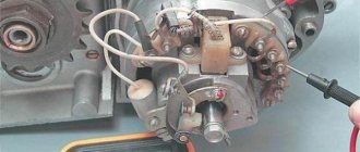
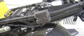
Regulator relay ( 5 ). People may call it a “stabilizer”, “transistor”, “regulator”, “voltage regulator” or simply “relay”. All these definitions refer to one piece of hardware. This is what the relay regulator looks like.
The relay regulator on Chinese scooters is installed in the front part under a plastic fairing. The relay-regulator itself is attached to the metal base of the scooter in order to reduce the heating of the relay radiator during operation. This is what the relay regulator looks like on a scooter.
In the operation of a scooter, the relay regulator plays a very important role. The task of the relay regulator is to convert the alternating voltage from the generator into direct voltage and limit it to 13.5 - 14.8 volts. This is the voltage required to charge the battery.
The diagram and photo show that there are 4 wires coming from the relay-regulator. Green is the common wire. We have already talked about it. Red is the output of positive DC voltage 13.5 -14.8 volts.
The regulator receives alternating voltage from the generator through the white wire to the relay. Also connected to the regulator is yellow wire coming from the generator. It supplies the regulator with alternating voltage from the generator. Due to the electronic circuit of the regulator, the voltage on this wire is converted into a pulsating one, and is supplied to powerful current consumers - the low and high beam lamps, as well as the dashboard backlight lamps (there may be several of them).
The supply voltage of the lamps is not stabilized, but is limited by the relay regulator at a certain level (about 12V), since at high speeds the alternating voltage supplied from the generator exceeds the permissible limit. I think those who have had their dimensions burned out due to malfunctions of the relay-regulator know this.
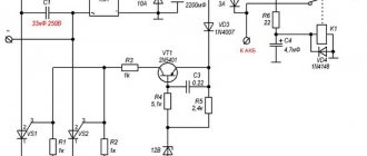
Despite all its importance, the device of the relay regulator is quite primitive. If you pick apart the compound with which the printed circuit board is filled, you will find that the main relay is an electronic circuit consisting of a thyristor BT151-650R , a diode bridge on 1N4007 , a powerful diode 1N5408 , as well as several wiring elements: electrolytic capacitors, low-power SMD transistors, resistors and a zener diode.
Due to its primitive circuitry, the relay-regulator often fails. Read about how to check the voltage regulator here.
Types of scooter switches
Before connecting the switch, it is important to know what type your scooter requires. If you connect the wrong device or do it incorrectly, the switch will immediately fail. The problem is that the part has the same plugs, but you can tell them apart. It's worth starting with the fact that DC is much larger in size.
AC CDI is much more common. It is installed on most Chinese and some Japanese vehicle models. Most often, such a switch is found on those scooters that have a 139QMB or 157QMJ engine.
A slightly different AC switch is installed on “Alpha”, “Delta” mopeds, and other equipment with a 1P39FMB motor. Such a switch operates from a generator coil and requires alternating voltage
DC has a different type of power supply - from a battery, so it has
12V, and if you connect it to a generator, the switch will break. AC is more durable in this regard; most likely, it simply will not work until you connect it correctly.
Relay regulator
This is the same rectifier that converts alternating voltage to direct voltage, with a range of 13.5-14.9 V. C
.
The regulator is located under the plastic cover of the scooter at the front. It is attached to a metal backing for better heat dissipation.
The main circuits of the relay circuit are:
- The green wire is common.
- Red – output of converted and stabilized voltage within the established limits.
- White and yellow – AC input to the regulator. Due to electronics, the voltage is converted into powerful impulses. The yellow wire supplies power to a heavy load on the on-board network - headlights and instrument panel lighting.
The current for lamps is not stabilized, but is limited to acceptable values. At high generator speeds, the voltage goes beyond the operating ranges of the lamps, which leads to their burnout. The situation is very familiar to those who have encountered faulty relay regulators.
Because of one unit, you can lose all the light bulbs in a matter of seconds, so you should monitor the on-board voltage regularly.
How to set the ignition on a Honda Dio When choosing, pay attention to the presence
Ignition on Audi Alexander Category: Setting the ignition of the Audi 80 is carried out according to 3 marks: Then, designed specifically for asphalt, the car, along with certain basic cars, began the new era of parquet jeeps. For the base we took the Honda Civic, and the name of the car itself stands for Comfor. 2 Honda Dio 27 fit the ignition coil. How to set the ignition Look at the color of the commutator wire, you can find it in the commutator connector.
Remove the protective cap from the ignition switch. Select the wires that go to the ignition switch.
The wire that matches the color of one of the wires that goes to the switch is the wire silencing the scooter. It remains to determine the purpose of 2 wires - from the electromagnetic sensor and from the supply coil.
The black wire with a red stripe is usually from the electromagnetic sensor, the second is from the supply coil. The ignition timing on the scooter does not start. Honda Dio 27 won't start Video.
How to set the ignition on a Honda Dio scooter
Scooter ignition system, diagram, operation, clearly, in simple language - accessible to beginners. Knowing the principle of operation. Elsheep-Team Honda Accord 8. In any case, it is positioned that way.
One of the standard configurations has a very extensive audio system.
How to correctly adjust the ignition on a VAZ Most car owners who have a VAZ car may have encountered difficulties associated with the correct operation of the engine. A common problem is that turning the engine key starts it, but the engine does not respond correctly to idle ignition.
And the box just opened: Dio switch
Yesterday I encountered a problem connecting the switch from Dio 35 to Dio 34. I couldn’t find a good diagram on the Internet, there were too many different schemes and all kinds of collective farms, so I had to make my own. First, I looked at how the standard switch is installed on my 34:
On the net I found a couple of normal photos of connecting to the 35:
There is essentially no fundamental difference between them. The whole difference comes down to the fact that on the 35th Dio the switch must be rotated 180° and connected in the same way as the 34th. As a result, this banal scheme was born:
Because My hole was disassembled, I had to test it experimentally on a friend’s scooter. Everything is working.
PS If you have the 5th pink wire from the zener diode of the ignition switch, then you don’t have to worry, without it everything works fine.
Other entries in this logbook
Got to the fuel station
Updated Dio 34 chassis
ICE: Part 3. Still collected
After assembling the variator, a question arose about the cover. The original GBL, to put it mildly, did not live up to expectations, being rubbed through and through by the leg. Read more
Comments
Only authorized users can leave comments
Ukraine
Honda Dio "34 Cesta"
Honda Dio AF 34 Cesta. Small, economical, a real “hard worker”, but forgotten for many years. Painted with a broom with floor paint in a thousand layers. The rubber is worn, like the head of a “tough nut.” Everything falls away, the bolts are from KamAZ, and the screws are from grandma’s wardrobe. A shepherd tried to ride this crazy stool and tore up the entire seat. The plastic in the pile is held together only by a layer of dirt, and the mirrors were blown away from the cosmic speed it developed. It can run on wood, but it starts with a hammer drill attached to the shaft. It seems that this moped is going to die in a landfill, but for me this is an opportunity to simply delve into the technology and breathe new life into a once wonderful scooter. Let's see what happens with a little work.
Source
Wiring diagram Honda Dio AF 18, 27, 28 – Scooter Garage, Kherson
The repair of this scooter is no different from other devices in this line.
Instructions manual for honda dio 18 diagram and repair of electrical equipment Honda Dio AF 18, 27, 28, which you will find below, is an electrical diagram on which all electrical elements, electrical equipment and wiring are identified in detail.
Thanks to this diagram, you can identify electrical problems.
honda dio 18 diagram The orientation of the diagram is very simple and intuitive. If this instruction did not help you, or you have any questions about the repair and maintenance of the Honda Dio scooter models AF 18, 27, 28, you can ask your questions in the comments field below, as well as share your own impressions and experiences during the operation of these scooters.
If necessary, sealing gaskets must be sealed with a sealant to prevent leaks. Carefully follow all specifications regarding tightening torque values honda dio 18 wiring diagram. Identification Serial numbers are marked in the places indicated in the figure: Honda scooters differ from other brands in having a more durable and heavier design and rather durable motors that are less susceptible to boost.
The weak point of regular Dio is the front fork boots. When they crack, they allow dirt to enter the fork - as a result, the bushings and feathers quickly wear out and fail. In addition, regular Dios have a somewhat unfortunate CVT setup with dip and pick-up, which makes a quiet ride difficult.
On more expensive Dio ZX models, these shortcomings are corrected. Scooters of the Tact family are designed for novice drivers. A threaded rod is rigidly welded to the exhaust pipe 1 5.
Guide movable pipe. Expanding muffler resonator cone.
Minimum length limiter. This has long been used by water sportsmen on racing scooters.
Moreover, they change this length directly while driving along the distance, depending on the operating mode of the engine and the Honda dio 18 circuit maintains relative power over a wider speed range. It's helpful to go to a powerboat competition and see the moving tube system on racing scooters. Here I presented a fixed scheme for changing the length, but I think you understand the meaning of why this is all necessary.