Changing the engine oil
In 2-stroke technology, the oil does not change, but is regularly poured into a separate tank and supplied by an oil pump to the carburetor, where it is mixed with the air-gasoline mixture and supplied to the engine.
The mixture lubricates the rotating and rubbing parts of the engine, burns and exits with exhaust gases into the exhaust pipe.
Oil tanks on scooters have different volumes - from 0.6 l to 1.3 l.
If you ride a motorcycle every day, then five liters of oil will be enough for a 2-stroke engine for the summer season.
The Oil lamp on the instrument panel indicates that the oil has dropped to the reserve level.
If the lamp lights up, it means that there is little oil left in the tank.
We'll have to capitalize on it. And this, you understand, is time-consuming and expensive repairs.
On 4-stroke 50 cc motorcycles, the oil is changed every 2 - 3 thousand km. During this mileage, fuel combustion substances accumulate in the oil and, as a result, it becomes dirty and thick, which changes its structure and properties.
If you drive together, transport cargo, that is, when the engine often works under heavy loads, then change the oil more often, after 1 - 1.5 thousand km.
Let's get down to business.
Start the scooter for 5 - 10 minutes. until the increased speed drops.
Place the motorcycle on the stand and turn off the engine.
Loosen the drain bolt.
Place a liter jar to drain the waste and unscrew the bolt completely.
Then unscrew the oil dipstick.
In 5 minutes, all the oil will flow out of the engine.
On a Honda Dio 56, there is a filter mesh under the oil drain cover. Wipe it well with a dry cloth and blow it or rinse it in gasoline.
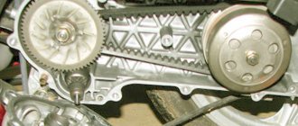
On a Honda Dio 68, the oil filter mesh is located near the variator. The mesh also needs to be removed and washed.
Then reassemble everything in reverse order.
Fill the engine with oil through the dipstick. Its quantity depends on the motorcycle model and is indicated on the oil dipstick.
The level should be up to the top mark of the dipstick.
As you can see, the procedure is not complicated, but it requires care and will take 20–30 minutes. It's always difficult to start the first time, but then it will be business as usual for you.
How to check the fuel pump on a scooter?
Summer. Time for the sensations of driving both cars, motorcycles and scooters. A scooter, according to reviews from travelers, is a convenient and fun technology. On it, if systems and parts are checked and adjusted, movements are made along asphalt roads over vast distances. One of the parts that plays a role in the proper functioning of gasoline in the engine operating system is the scooter's fuel pump. Let's take a closer look at the purpose for which a fuel pump on a scooter is used, and how this part works.
On what models is it installed?
The fuel pump is installed on various models of scooters. The most common ones are presented below.
The scooter's fuel pump plays a role in the proper functioning of gasoline in the engine operating system.
On Japanese models:
- Honda Dio - easy to use, with a glove compartment that allows you to store a helmet and other things on the go, tank capacity is 4-6 liters;
- Vamaha Jog – has great maneuverability, the volume of the power unit is 49 cubic centimeters.
On Chinese scooters:
- Suzuki Address V110 is a two-stroke with a medium speed engine, its wheelbase is designed for movement around the city and beyond;
- Viper Storm 150 is a two-seater, reliable, comfortable model.
Gasoline pumps are installed on equipment from Russia - a manufacturer in Yoshkar-Ola, an official dealer of Polaris and the Russian brand of several companies Irbis:
- Lifan LF 125T-27 - it has a four-stroke engine, 125 cubic centimeters, speed 80 kilometers per hour, gas tank capacity 5 liters;
- Irbis Z50R is a high-speed scooter for driving outside the city with wide tires.
Features of operation and spare parts
Gasoline is poured into one of the holes in the tank. The fuel pump automatically opens when the engine starts, and closes its second hole when it stops. In this case, a vacuum occurs, affecting the opening of the gas tap to supply fuel to the pipeline. Then, through the gasoline filter, the fuel enters the carburetor, where it is mixed with the air that has passed through the air filter. At the same time, the filters clean gasoline and air from foreign impurities, respectively, protecting scooter parts from damage.
Types of oil pumps, their design and operating principle
The pump's task is simple: pump motor oil in a circle. But there are several design options, since engineers all over the world continue to improve every, even the smallest, component of the car.
By design, pumps are rotary, gear (with external and internal gears) and vane (plate).
- The simplest gear oil pump consists of two gears with elongated teeth, installed in the working chamber so as to mesh. One of the gears is connected to the pump shaft, that is, it is driving, the second is driven, and rotates only due to engagement with the first. Engine oil is picked up by the gears during rotation and transferred to the opposite side, into the oil passages. This is a diagram of an external gear pump.
internal gear pump
Rotary
A vane pump is a working chamber into which a cylindrical rotor with slots is inserted. Flat slide plates are inserted into the slots and can move freely in these slots. When the rotor rotates, the space between it and the walls of the working chamber is divided into sectors. These sectors capture portions of liquid and transfer it to the discharge channel. The design of the vane pump allows you to adjust its performance by moving the stator and thus changing the volume of the working chamber.
Based on adaptability, a distinction is made between adjustable and unregulated types of pumps.
- The former have the ability to change performance depending on the engine’s current need for lubrication. Adjustable pumps ensure that the engine receives as much oil as it needs at all times.
The performance of unregulated pumps depends solely on the speed of rotation of the crankshaft.
For most cars, this is quite enough, unless you tune them for racing. To avoid creating too high pressure in the lubrication system when the engine gains power, unregulated pumps are equipped with a pressure reducing valve. It opens when the pressure reaches a critical point, and part of the oil goes back into the crankcase, that is, it serves to stabilize the pressure in the lubrication system. Pump drive types are electrical and mechanical.
- Electric oil pumps are quite rare as a design solution. They are used in turbocharged engines designed for high (sports) loads. The electric drive is needed to ensure that the pump continues to operate after the engine stops, cooling the hot turbine.
- Mechanical oil pumps driven by the engine crankshaft are used in most vehicles. The drive can be belt or gear, it depends on the design solution. The speed of the pump (and its productivity per unit time) depends on the load on the engine. This has its own logic: the faster the motor runs, the more it needs cooling, cleaning and lubrication.
Where is the oil pump located? If we talk about a lubrication system with a “wet” sump, that is, a conventional one, then in it the pump is located at the bottom, supplying oil to the system from the sump, from the bottom up. If this is an unregulated pump type, then when excess pressure is created, excess oil will drain through the pressure relief valve back into the crankcase. One pump is enough for a conventional engine.
A dry sump lubrication system, where a separate reservoir is provided for oil, is installed on powerful sports cars, which means it is designed for high loads. Two or even three oil pumps can be installed on such an engine, since at maximum speed such an engine requires both cooling and lubrication.
Classification and selection basics
Today, three main classifiers are used in the world to describe the properties and scope of application of two-stroke oils:
Let us consider only the current standards in force today. There is no point in reviewing outdated and out-of-use classifications, since they are almost impossible to find on sale today.
According to SAE, two types of motor oils are common today: TD and TC-W3. The first type, TD, is suitable for most two-stroke engines in use today. Lubricants marked TC-W3 are intended for outboard internal combustion engines. The main difference between these lubricants is their high environmental friendliness. There are no significant differences in performance characteristics.
According to JASO, today you can find oils marked FB, FC and FD. Quality and performance increase as the second letter moves away from the beginning of the alphabet. Lubricants marked FB are suitable for low-load engines without specific requirements.
| Test parameters for JASO and ISO | ||||
| ISO | — | E.G.B. | E.G.C. | EGD |
| JASO | F.A. | FB | F.C. | — |
| Lubrication properties | 90 min | 95 min | 95 min | 95 min |
| Torque index | 98 min | 98 min | 98 min | 98 min |
| Cleaning properties | 80 min | 85 min | 95 min | 125 min |
| Deposits on the piston skirt | — | 85 min | 90 min | 95 min |
| Smokiness | 40 min | 45 min | 85 min | 85 min |
| Deposits in the exhaust system | 30 min | 45 min | 90 min | 90 min |
Category FC has reduced smoke emission. FD, in addition to reduced smoke, has increased cleaning properties.
The ISO classification is based on the Japanese JASO. However, several additional levels of testing have been introduced here, which every certified oil must pass.
Similar to JASO, there are three classes:
In the case of ISO classification, the first two classes additionally carry out tests for the cleanliness of the pistons after use. The last class must pass a detergency test.
Standards for two-stroke engine oils - video
Causes of oil pump failure
The reason why the oil pump has failed can be determined by diagnostics. There are at least 8 main oil pump faults. These include:
- Clogged oil pickup strainer. It is located at the inlet of the pump, and its function is to coarsely filter the engine oil. Like the system’s oil filter, it gradually becomes clogged with small debris and slag (often such slag is formed as a result of flushing the engine with various means).
- Malfunction of the oil pump pressure reducing valve. Usually the piston and spring included in its design fail.
- Wear of the inner surface of the pump housing, the so-called “mirror”. Occurs for natural reasons during engine operation.
- Wear of the working surfaces (blades, splines, axles) of the oil pump gears. It happens both over time of long operation and due to rare changes of (very thick) oil.
- Using dirty or unsuitable engine oil. The presence of debris in the oil can be for various reasons - careless installation of a pump or filter, use of low-quality lubricating fluid.
- Careless pump assembly. In particular, various debris was allowed to get into the oil or the pump was not assembled correctly.
- Drop in oil level in the engine crankcase. Under such conditions, the pump operates at excessive capacity, which causes it to overheat and may fail prematurely.
- Dirty oil filter. When the filter is very clogged, the pump has to make significant efforts to pump the oil. This leads to its wear and partial or complete failure.
Regardless of the reason that caused the partial failure of the oil pump, it is necessary to carry out a detailed check of it and, if necessary, make repairs or complete replacement.
Possible malfunctions and their symptoms
The resource of the unit is quite large and is about 100,000 kilometers.
How can you ensure that the oil pump does not fail prematurely? The condition for it to last the allotted time is regular replacement and topping up of oil, and periodic cleaning. In this case, only high-quality oil mixtures should be used. However, the device may fail. The following may be “symptoms” of a breakdown.
- Decrease or increase in operating oil pressure. This is indicated by a corresponding light on the vehicle’s dashboard.
- Increased oil consumption.
The following malfunctions may be the causes of such manifestations.
- The oil receiver screen is clogged. If dirt gets in there, it prevents the normal passage of fluid, resulting in the failure to provide the required pressure. The problem is solved by cleaning.
- Valve failure. If the pressure relief valve fails, no relief occurs when the pressure increases significantly. Eliminate the malfunction by replacing the failed part.
- Mechanical wear. Both the internal surface of the housing and the moving elements (gears, rotor, stator) are susceptible to it. If there is minor wear, you can replace the part that has become unusable. If it is significant, the only way to solve the problem is to completely replace the device with a new one.
- Poor quality oil. Some brands of lubricants do not have sufficient fluidity. As a result, problems may arise. The solution is to drain the old one and pump in new lubricant.
- Leak in the crankcase. Due to mechanical damage to the crankcase, lubricant may leak. In this case, the pressure drops and the oil pump begins to work more intensely. Solve the problem by eliminating the cause of the leak.
Complication of design
Using the example of a 2.5 liter diesel engine from VW, you can see how much more complex the operation of the lubrication system of a modern engine has become. Let's look at the purpose of each of the elements.
- Two-stage internal gear type oil pump. Installed in the oil pan.
- Oil pressure regulating valve. Using a solenoid valve, the ECU (Engine Control Module) directs oil to different channels, thereby switching the operating modes of the oil pump. When regulating performance, the engine load, coolant temperature, crankshaft speed and signals from the automatic transmission are taken into account. When a control signal is applied, the valve opens, allowing oil to flow into the channels of the first stage (the pressure in the system is about 1.8 atmospheres). In the absence of a control “mass”, the return spring returns the valve to its original position, changes the direction of oil flow, raising the pressure in the system to 3.3-4 Atm.
Changing the performance makes it possible to reduce the mechanical losses spent on lubrication and cooling of the engine’s rubbing pairs. This solution increases the overall efficiency of engines, reducing the amount of harmful emissions.
- Check valves in return lines. They allow lubricant to flow in only one direction and prevent complete drainage of oil from the channels after the engine is stopped. Filled channels allow you to avoid oil starvation in the first seconds after starting the engine.
- Safety valve. Opens during a cold start when excessive pressure develops in the system.
- Small circuit valve. Triggers when the filter element is clogged, opening the way for oil to bypass the filter.
- Oil cooler. Oil and coolant circulate through the heat exchanger housing.
- The cooler helps maintain the thermal balance of the engine and prevents oil overheating.
- Oil injector valve. It opens when the design pressure is reached in the system, opening the line to the injectors.
- Oil nozzle. Sprays oil onto the piston crown, removing heat from it.
- Pressure reducing valve. Triggers when excessive pressure is reached in the system, protecting the cylinder head from excess oil.
Chainsaw oil pump - purpose
The idea of using an automatic oil pump to lubricate parts is not new; using increased oil pressure to penetrate hard-to-reach cavities has been around for a long time. The oil pump is successfully used in internal combustion engines when processing parts using an oil emulsion, so the idea of lubrication of the working part of a chainsaw using an oil pump has become widespread and used.
A saw chain, consisting of connecting links and links with cutting teeth, when working when heated, requires overcoming a large friction force, both at the joints of the links and in the form of wood.
In addition, the working guide bar along which the chain moves must also be constantly lubricated from the attachment point to the gear at the end.
The chainsaw oil pump is designed to ensure effective lubrication of these two elements.
Changing the oil in the gearbox
At the very bottom of the engine, on the left side in the direction of travel, we are looking for the drain and filler plug of the gearbox. The filler plug is located on the side or on top, and the drain plug is always at the bottom.
Place a container under the drain plug and unscrew both plugs.
We wait about ten minutes until the old oil drains from the gearbox.
Let's take the oil. I take a liter canister, it’s cheaper and lasts for about 10 replacements. If you change oil infrequently, buy a special tube of branded oil for scooter gearboxes. There is more than enough of it for one replacement, and without unnecessary headaches, pump it into the filler hole using a special spout.
For those who prefer to save money, there is only one thing left to do: pump oil into the gearbox in small portions using a regular syringe. Unfortunately, there is no other way to fill the gearbox with oil because the filler hole is too small.
Checking the oil level in the gearbox
We pump oil into the filler hole, also known as the control hole, until it begins to flow out of it. As soon as the oil starts to flow, stop pouring, wait a couple of minutes for the excess to drain, and tighten the plug.
Source
Oil pump, what is it? Concept and purpose of an oil pump
A car oil pump is a device that creates pressure on the lubricant in the system, so that it flows to the moving elements of the internal combustion engine. Pressure is necessary to supply lubricant (oil) to those engine elements that require forced lubrication, for example the camshaft located in the cylinder head, that is, much higher than the oil tank and without the pressure created by the oil pump, lubricant will not reach it
The car oil pump is driven by the crankshaft or through the drive shaft from the camshaft
According to the nature of control, they are divided into two types: adjustable and unregulated
- Adjustable - thanks to the ability to regulate performance, it creates stable pressure in the system
- Unregulated - constant lubricant pressure is maintained due to the presence and operation of a special pressure reducing valve
Depending on the design, they are also divided into:
1. Rotary type - pressure is created due to the rotor blades
2. Gear type - the oil receives pressure due to the operation of gears.
They in turn are divided into:
- external gears - when two gears are located next to each other,
- internal gears, when one gear is located inside another.
The difference in gear placement does not affect performance, but does affect the size of the device. Due to the fact that the gears are located in each other, much less metal is required to accommodate them, and therefore the internal gear is smaller in overall dimensions
Features of two-stroke oil - ISO standard
One of the global classifiers when selecting lubricants for internal combustion engines is the design of the motor. Based on the number of individual completed operations, so-called strokes, modern piston engines are divided into:
Almost all motorcycles and cars, as well as other heavier equipment, are equipped with four-stroke engines. Two-stroke engines have occupied a niche among small-displacement and cross-country motorcycles, various portable tools, light water transport, as well as in several other industries.
In this article we will look at the features of two-stroke oil, and also briefly examine some important points of application and the basis of choice.
Troubleshooting and repair of a removed element
Let's look at how to test a removed oil pump. The check consists of visual inspection, measurements and comparison of the measurement result with the nominal dimensions.
Unscrew the oil receiver cap together with the pressure reducing valve. It is worth making an effort so that the spring thrust washer does not get lost
Next, note that some bolts will be smaller than others. This bolt should then snap back into place.
Use a caliper to measure the spring. At rest, it should be at least 38 millimeters in length. Then remove the cover, which will have marks from the wear of the gears. If the scoring is deep, then the oil pump has a lot of wear. The cover can be repaired - its plane should be leveled.
Next, remove the drive gear and visually check the condition of its teeth. If there are abrasions and burrs on the teeth, this indicates a lot of wear. The driven gear should also be checked. The main thing about it is the hole in which the fixation axis is located.
Then check the walls of the device housing and the axis of the driven gear. Potholes, grooves, and various defects indicate that debris has entered the working area inside the pump.
What to do if the lamp is on?
As we said earlier, a special indicator lamp will indicate low pressure. What are our actions if we find ourselves in such a situation? First of all, you need to turn off the engine. Next, open the hood and check the oil level. It also happens that the lamp lights up due to its low level. If the dipstick is normal, you need to look deeper for problems. But this must be done in a garage or service center. It is better to get to the repair site by tow truck.
When is a burning lamp normal? It only appears like this after a cold start. In the first seconds, the pump cannot yet generate the required pressure. But if the motor has been running for 30-50 seconds, this clearly indicates a problem.
Cooling system
All Nexus scooters are equipped with a forced air cooling system. It is needed to prevent jamming and damage to parts due to overheating, which causes excessive expansion of the piston, as well as disruption of lubrication conditions. Since the motor of all scooters is covered with a casing and is located under the seat in the rear, the flow of oncoming air cannot effectively cool it. Therefore, a fan impeller is used, mounted on the right side of the engine on the generator rotor. This centrifugal fan forces air under a casing that covers the outside of the cylinder and cylinder head.
Cooling system details:
- fan impeller;
- casings
Useful tips
It is quite obvious that even such a reliable solution as an oil pump has a limited service life. Of course, in order to increase the service life, it is necessary to take into account the reasons for oil pump breakdowns discussed above. Understanding the reasons allows you to avoid such troubles.
First, you should always change the oil and oil filter regularly, and also monitor the engine oil level and its condition. If it is clear that the oil has become very black, its viscosity has changed, and problems arise with oil pressure in different operating modes of the internal combustion engine, you should check the lubrication, as well as the functionality of the engine oil pump.
If it is necessary to inspect and replace the oil pump, you must also replace the engine oil and oil filter, as well as thoroughly clean the engine crankcase, check the condition of the pressure relief valve and oil intake. It is also recommended to completely flush the lubrication system before adding fresh oil.
Instructions: how to replace a cylinder in a two-stroke scooter or motorcycle
21.02.2019
Two-stroke engine with a very progressive fuel system
Before moving directly to the article, I consider it necessary to write about a funny incident that happened in the workshop and, in fact, led to the writing of this short instruction.
It was in the summer, I was talking with one very competent auto mechanic, he was talking about pistons. I listened carefully and, as if by chance, I remembered two-stroke motorcycle engines. He ignored my digression and continued to tell me how progressive STK pistons are in comparison with the Chinese miracle of technology and how easy it is to install oil rings. For some reason I again remembered two-stroke engines, and he again turned a deaf ear to my question. The fourth time he couldn't stand it anymore. “Why are you getting into a serious conversation with your two-stroke guys! – the mechanic was indignant. - Now they no longer exist, now everyone rides on four strokes, as expected, with valves! Nobody drives two-stroke engines anymore!”
Before he had time to finish his sentence, two guys on a heavy, heavily smoking IZH-Jupiter 4 motorcycle rode a meter away from us, at breakneck speed. We laughed for a very long time.
And IZH-Jupiter is not the only representative of two-stroke technology; many Japanese and Chinese scooters and mopeds contain a two-stroke power unit under plastic. Therefore, in our opinion, the instructions for replacing pistons and cylinders in 2-cylinder machines are very relevant. From a methodological point of view, mastering the principles of operation of a 2-stroke engine is an excellent way to study the principles of operation of motors in general.
In 2T engines, there are two main methods of increasing power: replacing the exhaust system with a new one with a different performance characteristic and replacing the cylinder injector with a new one with a higher performance. Before starting work, we must prepare an engine service manual (if available), sets of combination wrenches or socket wrenches of the most popular sizes (7, 8, 10, 11, 12), several adapters (preferably tapered to the tip). It is also worth equipping yourself with a torque wrench necessary for tightening the head - the simplest model can be bought for 500-600 rubles.
Removing the piston on a 2T scooter
Step 1
Adjust the crankshaft so that the connecting rod is as close as possible to the position where the piston reaches GMP. The hole in the cracks should be covered with fabric or foil material with holes for the cylinder and crank pins. This will prevent parts from falling into the crankcase.
Remember! When replacing a cylinder, do not skimp on the crank bearing.
Step 2
All work should begin with a new connecting rod head bearing, which should be replaced every time the cylinder is replaced. Remove the old bearing from the connecting rod, coat it with engine oil and place it in the hole - this is a very simple operation.
Piston Pin Needle Bearing
We take the plunger and place the pin on one side - to secure it with tweezers, place the guard in the marked groove and press it - the wire will deform so that it can be inserted. Some guards have two tabs, just long enough to catch them, squeeze them and place them in the piston.
Step 3
The next step is to put the rings on the piston. Because two-stroke engines are so confusing, you should always count the rings from the top of the piston. If there are two rings on the piston, and we cannot immediately put on the lower ring, we first put it on the upper groove, and then transfer it to the lower one - it is worth helping with a needle or pin.
Oil pump. Theory and practice.
Oil pump
can be called a hydraulic mechanism (machine), which, by analogy with a hydraulic pump, converts the mechanical energy of the mover (muscular energy of humans or animals for hand pumps) into the energy of the flow of oil fluid and serves to transport and create pressure of the oil fraction and their mixtures.
Oil pumps have different classifications according to their application:
To create pressure in lubrication systems of various mechanisms;
For pumping (transporting) oil-containing liquids from/to containers/containers, as well as for pumping and pumping oil from/to containers and mechanism components;
For household use.
Oil pumps are also classified according to the nature of their controllability and are divided into:
Adjustable, when control over the main parameters of the pump is carried out through automatic control units or mechanical regulators of the main parameters of the pump and propulsion unit;
Uncontrolled, when the operation of the pump is controlled, but its parameters cannot be changed by external influence.
Classification of oil pumps by design differences:
- Gear-type oil pumps, which in turn are divided into 2 types - an external gear pump (gear around a gear) and an internal gear pump (gear in a gear). This is the joint work of the drive and driven gears, when oil enters the pump through the suction channel, is captured by the gears and is pumped into the system through the discharge pipe. Their performance is directly dependent on the speed of the engine shaft (mechanical impact);
1. Driven gear;
2. Suction channel;
3. Drive gear;
4. Drive shaft;
5. Discharge channel;
6. Driven gear axis.
The oil pump is a rotary type, which in its housing design combines the work of 2 rotors (internal - driving and external - driven). The oil is captured by the blades of both rotors and enters the pipeline system under pressure.
1. Suction cavity
3. External rotor
4. Discharge cavity
5. Drive shaft
6. Inner rotor
This type of oil pump can be regulated or unregulated. Adjustable rotary oil pumps operate on the principle: when the frequency of the engine drive shaft increases, the pump consumes a larger volume of oil and the pressure in the system drops, the spring mechanism is activated and shifts the position of the stator relative to the movement of the pump rotor, thereby increasing the volume of the pump cavity, which leads to an increase in oil pump performance and vice versa.
A - Discharge side B - Suction side
Piston oil pumps are mechanisms in which the principle of suction of oil-containing liquid and its expulsion occurs due to the reciprocating movement of the piston (pistons) (plunger) in the housing cylinder with at least 2 check valves.
Vane (vane) oil pumps are adjustable units that have an eccentricity adjustment system (installation of the rotor shaft in the volume of the oil cavity). The operating principle of the pump is based on changing the volume of the suction and discharge cavities due to the non-coaxial rotation of the rotor in the pump chamber.
Impeller oil pumps, in which the movement (transportation) of the oil-containing fraction is carried out due to the impeller blades, which create a difference in fluid pressure at the inlet and outlet of the pump chamber. The impeller performs reciprocating movements and two pairs of valves (inlet and outlet). When the impeller moves, the pumped liquid moves from the suction cavity to the discharge cavity. The valve system prevents fluid flow in the opposite direction;
Rotary-type oil pumps, in which the movement of an oil-containing substance is carried out by 2 shafts with a specific cross-sectional profile. According to the principle of operation, the rotary lobe pump is positive displacement. When the driving and driven rotors rotate, a vacuum is created on the inlet side, causing fluid to move from the inlet side to the outlet side. At the outlet, when the cams engage, fluid is squeezed into the system. The pump consists of the following main parts and assemblies:
— drive and driven shafts with a rotor, rolling bearings and gear installed on each of them;
Features of a two-stroke engine
Two-stroke internal combustion engines have some differences in operating principle relative to four-stroke ones. This type of engine, just like a four-stroke engine, includes a crankshaft, connecting rod, piston and cylinder.
However, the gas distribution mechanism here is implemented not with the help of a camshaft and valves, but with a set of so-called windows for various purposes.
In general, for the simplest models of these internal combustion engines, there are three windows:
The purge and outlet port is opened and closed by the piston body. The piston in two-stroke internal combustion engines has a uniform elongated skirt. The purge window can be closed with a special valve or, like the other windows, with a piston.
There are two windows on the fuel supply side. The inlet, which is located below, and the purge, which is located above. Exhaust gases exit through the exhaust window, which is located on the opposite side.
The fuel-air mixture from the carburetor or injection system enters the chamber in front of the intake port. The intake port does not have a direct connection with the cylinder. It opens access to the hollow space under the piston chamber, where the crankshaft with connecting rod is located.
The crank chamber is isolated from the environment. When the piston rises, a vacuum is created in the chamber. And closer to top dead center, the fuel-air mixture is sucked into the space under the piston.
As the piston moves downwards, towards the end of the power stroke, the exhaust window first opens, through which exhaust gases are released into the atmosphere under pressure.
Next, a purge window opens, through which fresh mixture is pumped into the combustion chamber. The fresh mixture pushes out the exhaust gases completely. The cycle repeats.
There are other designs with more complex organization of circulation of the fuel-air mixture and exhaust gases. However, the design in question is basic, and it fully describes the essence of the operation of two-stroke engines.
The piston, cylinder walls and connecting rod bushings are lubricated by oil dissolved in the fuel. That is, there is no oil in the crankcase of a two-stroke engine, specifically in the crank chamber.
Two-stroke engine oil is added only to fuel. Lubrication in its traditional sense is found only in the gearbox and sometimes in the compartment with the clutch discs. It is these operational features that determine the properties of two-stroke oil.
Design of a car engine lubrication system
Engine lubrication system
The main task of the lubrication system is to provide an oil film on the contacting moving parts of a car engine. This helps reduce power loss and wear of the power unit. In addition, the oil supplied by the system is used in hydraulic tensioners and in valve timing control mechanisms. In the general design of the car, the lubrication system is integrated into the engine structure and consists of the following elements:
- Filler neck - oil is filled or topped up through it.
- The oil pan is the lower part of the engine housing filled with oil. For proper engine operation, the amount of working fluid in the sump must be at a certain level, which is measured using various sensors and devices (dipstick). Not only excess oil flowing from the engine mechanisms accumulates in the sump, but also contaminants formed during operation. Also on the pallet there is a drain hole and a plug in the form of a bolt with a washer. When changing the oil, the plug must be replaced along with the washer.
- Oil intake - is a structure consisting of a pipe running from the sump to the pump and a coarse filter.
- – sucks up lubricant using an oil intake from the sump and supplies it to the system. It starts and stops simultaneously with the engine. The drive can be a crankshaft, a camshaft or an auxiliary drive shaft. As a rule, two types of pumps are used in cars for pumping oil: gear (more popular) and rotary.
- Oil filter. It is installed at the pump inlet and is designed to clean the working fluid from chips and carbon deposits. There are two types - dismountable (when the filter is dirty, only the filter element is replaced) and non-dismountable (the entire filter is replaced).
- Oil radiator. Since the working fluid in the lubrication system also cools, it passes through a radiator to reduce its own temperature. The latter, in turn, is cooled by the cooling system fluid.
- Lines and channels - oil moves through them from one unit to another.
- Oil nozzles. Used to supply oil to cylinder walls and pistons.
- Pressure, temperature and oil level sensors - send signals to the electronic engine control unit, transmitting data on the state of the lubrication system and engine operating mode.
- Valves (bypass and pressure reducing valves). Allows you to automate oil pressure control and control its supply to the system. Such valves are mounted near the leading elements of the system (pump, main engine components, filter).
Some engine models may not have sensors or a radiator. In this case, the oil is cooled directly in the oil pan.
Automatic scooter starter enricher
In order to start a cold engine without problems, you need a rich mixture (lots of gasoline and little air), and to operate the engine in normal mode, you need a regular mixture (the optimal ratio of gasoline to air is about 1:15).
On old scooters, motorcycles, cars, enrichment of the mixture when starting a cold engine was done manually in two ways: closing the air damper, thereby limiting the flow of air into the engine, or again manually, opening a special channel in the carburetor, through which an additional portion was injected fuel.
But opening and closing it manually is not very convenient, and to automate this process they came up with an automatic starting enrichment.
How does he work?
There is a heating element inside the enrichment body, through which, after starting the engine, an electric current begins to pass, under the influence of which the element and the capsule heat up as they come into contact with each other. Inside the capsule there is a special powder that, when heated, expands and pushes out the rod along with the needle.
This is what the enrichment looks like when cut.
Now let's look at how the enricher works in the carburetor itself.
When you start a cold engine (the enricher needle is raised), a vacuum is created in the carburetor diffuser, which through the wheelhouse sucks fuel into the enricher well, where it mixes with the air entering the well through the air channel and then through the main channel in the form of an enriched starting mixture enters the engine intake manifold .
After starting the engine, as it warms up, the element begins to warm up the capsule and the needle, together with the rod, gradually comes out and closes all channels in the enrichment well, thereby stopping the supply of the starting mixture to the engine intake manifold.
For clarity, we connect the enricher to the battery and after about five minutes the needle came out and blocked all the channels.
In conclusion, you will be shown a way to check the performance of the enrichment.
The state of the enrichment before starting (the engine is cold) connect the battery to it and after a few minutes the needle should come out.
As you can see in the photo, the needle came out, which means everything is in order with our enrichment, and if the needle does not come out, then the enrichment is faulty and must be replaced.
