For high-quality operation of any equipment, it is necessary to carefully monitor the condition of the parts, namely, perform adjustments and inspections in accordance with the regulations, check the reliability of each fastening, the operation of the engine and fuel system. Inspecting the snowmobile's variator is of particular importance in proper operation. The duration of the transport service depends on its operation. Stable operation is possible only with correct adjustment.
How to remove the belt part: first pull out the protection, separate the disks in the driven pulley. To replace the variator belt, you need to do the same.
The procedure for adjusting the Safari driven variator on the Buran snowmobile:
- Measure the distance between the inner ends of the plates at a distance of 3.5 mm from their border. You need to understand what set of washers to use in thickness. To do this, take measurements along the end of the plates. If the depth is 29 mm, but you need 33 mm, then choose a set of 3 mm washers.
- Unbend the locking plate and unscrew the bolt securing the fixed cone. Remove the 2 washers and screw the bolt back into place.
- Install the puller and remove the fixed cone
- Insert the adjustment washers into the center between the fixed cone and the half rings.
- Place a stationary cone.
- Tighten with a bolt and washer and make sure that the key is installed; it needs to be recessed by 2 mm. Wrap the locking one, locking it. Measure the distance between the cones so that it is within 31.5 mm.
Spread the cones and insert the snowmobile variator belt for replacement and adjustment, then tap with a block or hammer. The gap between the two elements should be 1 mm.
Popular brands
A set of mechanisms and equipment for motorized towing vehicles and snowmobiles is sold under different brands.
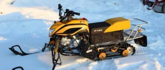
The Safari variator is popular; it changes the gear ratio and subsequently smoothly regulates the speed of movement of the equipment. This mechanism is also used for installation on a utilitarian snowmobile, for example, “Buran” or “Taiga”. This type of variator has a reinforced crosspiece, as well as a high-quality pressing mechanism. These two components contribute to the reliability of the product as a whole. Safari is lightweight, has a simple design, and is characterized by good reliability. With a mass of 3800 grams, the diameter of the mechanism is 21 centimeters and the length is 16.7 centimeters. The variator for the Forward snowmobile and motorized towing vehicle is also in demand among consumers. This mechanism is characterized by high quality construction, durability and reliability.
16.40. Scooter repair. Centrifugal clutch - removal and installation, replacement of pads
16.40. Scooter repair. Centrifugal clutch - removal and installation, replacement of pads
An assistant will be required to complete the work.
The variator cover is removed, the V-belt is removed (see Variator belt - replacement).
REMOVAL
1. Unscrew the driven pulley nut. This nut is tightened with a fairly large torque, so in order to unscrew it, you need to fix the pulley. It is best to use a special stopper, which is easy to make yourself, or simply insert a metal rod of suitable length between the clutch drum hole and the surface on which the scooter is installed. We put the spanner on the nut, lightly use a hammer to loosen the nut and unscrew it.
2. Remove the clutch drum from the shaft.
3. Remove the driven pulley assembly with the clutch block.
4. Inspect the clutch pads for wear and mechanical damage. It is necessary to make sure that the friction material of the pads has no mechanical damage, chips, deep scratches, and that the adhesive connection between the friction material and the pads is not damaged. If such damage is present, the pads must be replaced.
5. Measure the thickness of the friction layer on the pads. If the thickness is less than the minimum allowable specified by the scooter manufacturer (usually about 1 mm), the pads must be replaced
It is also important that the thickness of the friction layer on all pads is the same, and wear is uniform over the entire area of the lining
6. In order to separate the clutch assembly from the driven pulley, it is necessary to unscrew the central nut. To loosen the nut, it is necessary to clamp the assembly in a vice.
ATTENTION!
To avoid damaging the friction material of the pads, you should clamp the assembly in a vice with the minimum necessary force and use aluminum jaws or spacers made of any soft metal.
When holding the assembly in a vice, do not unscrew the nut completely, but only loosen it. Otherwise, the compressed spring, which is located inside the mechanism, will “shoot” and may cause injury.
7. We ask an assistant to firmly press the clutch to the pulley, as shown in the photo, and unscrew the nut. After this, the assistant gradually loosens his hands, allowing the spring to slowly unclench.
8. Remove the clutch assembly and spring from the pulley.
9. We inspect all parts for external damage. It is necessary to make sure that the halves of the driven pulley rotate freely, without jamming, relative to each other (in the driven pulley, as a rule, the halves are connected according to the “groove-key” principle. A bushing is rigidly attached to one of the pulley halves, on which the second half of the pulley rotates freely. Its movement is limited only by the oblique groove in which the key slides. It is this mechanism that ensures that the distance between the pulley halves changes when one half rotates relative to the other). If the sliding surface of the bushing is dirty, it is necessary to wash it with carburetor cleaner, kerosene or nitro paint solvent, and then lubricate it with penetrating silicone grease or engine oil.
It is also necessary to remove belt wear products (rubber dust) and clutch linings from all parts.
10. The clutch is ready to replace the pads.
11. Using narrow pliers, remove the retaining rings from the guide blocks.
12. Remove the pressure plate.
13. Lightly tap the center of the base of the assembly with a hammer handle to knock it out of the block package.
ATTENTION!
At the base of the unit, rubber dampers are installed under the pads. Once the pads move, the dampers may fall out. The dampers must be removed.
14. Remove the package of pads from the base.
15. Remove the springs connecting the pads and disassemble the pad package.
ATTENTION!
All springs in the clutch mechanism are calibrated. They are not allowed to be stretched, compressed or changed in shape. The springs connecting the pads must be of the same stiffness (usually the springs are color coded).
16. Before assembly, clean the clutch pad axles from dirt and old grease, and apply a thin layer of high-temperature grease to them.
ATTENTION!
Lubrication must be done carefully; after installing new pads on the base, remove excess lubrication. Contact of lubricant on the working surfaces of the pads is unacceptable.
INSTALLATION
Install the clutch in reverse order.
ATTENTION!
After installing the retaining rings on the axle, you need to rotate them so that the cuts of the rings are directed outward. This is necessary in order to protect them from spontaneously jumping off the axles under the influence of centrifugal force.
Next chapter
info.wikireading.ru
Regulator design and operation
The centrifugal action regulator includes a fixed cone 1 mounted on a shaft 12, a movable cone 3 with weights 2 that rotate on axes, a stop 4 with rollers 9 designed to move the weights, a spring 6, which is installed between the stop and the cover 5. Cone the fixed one and the stop are mounted on the shaft using a metric thread. Installation of these elements is carried out using a wrench with a tightening torque of 8-10 kgm. The spring moves the cones of the drive pulley apart when the engine speed decreases, thereby ensuring idle speed. At idle speed, the gap between the V-belt and the surface of the moving cone is 1-3 mm.
The regulator operates as follows: when the shaft rotates, centrifugal forces, acting on the weights, tend to rotate them and move the movable cone away from the stop, thereby clamping the belt in the pulley groove. The return spring counteracts centrifugal forces at speeds not exceeding 1600 rpm. As the engine speed increases, the cones grip the belt, increasing its tension and compression from zero to the nominal values required to transmit torque and overcome the forces of resistance to vehicle movement.
CVT (Page 1 of 117)
I'm talking about the parallelism of the movable and non-movable disks on the driven part, but what are you talking about? For paralysis of the leader and the slave