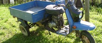
The Ant is still a fairly popular scooter, despite its advanced age and origins dating back to the times of the USSR. There are still many owners of such equipment. And increasingly, they have to deal with repairs and routine setup and maintenance issues.
One of the most frequently serviced components is the clutch. This mechanism periodically gets confused, which is why it requires adjustment.
In practice, adjusting the clutch is not that difficult. But in order to do this correctly and without errors, you need to at least become familiar with the device and operating principle. Plus, it wouldn’t hurt to find out what exactly could be causing problems with the clutch.
Repair of the clutch of the Ant scooter
In fact, the clutch of the “Ant” scooter is a very reliable, simple and almost “eternal” design.
There are often cases when the “ant” clutch worked for several tens of thousands of kilometers under conditions of intensive use, without any particular complaints about its operation. And on this engine, the clutch could well have lasted for more than one year if someone’s hand had not fit into it... While driving through the collective farm mud, a grinding sound was first heard from the engine, the speed jumped sharply to maximum and the “Ant” stood in the middle of the road dead weight, clearly making it clear to its owner that he does not want to go further. Attempts to start it were unsuccessful; the crank turned to idle. In general, there were all the signs of problems in the clutch.
Drain the oil from the engine and unscrew the clutch cover.
We unscrew the kickstarter fixing bolt (its purpose is discussed at the end of the article), remove the kickstarter shaft, unscrew the three nuts on the basket, and remove the pressure plate. Unbend the lock washer, take a 22mm socket wrench, place a tin rod or piece of wood under the chain and unscrew the nut.
We have unscrewed all the nuts, and now you can remove the basket along with the chain and sprocket.
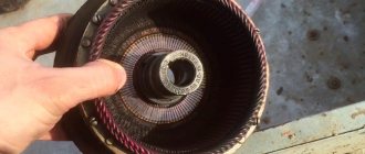
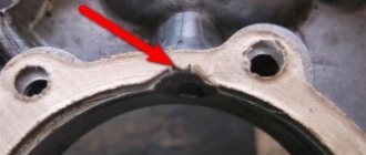
After a careful inspection of all the parts, it turned out that the splines on the inner clutch drum were cut off; I’ll tell you why this happened further.
For comparison, the drum on the left is not working properly, the drum on the right is working.
The splines were cut off because during the previous repair, they placed a too thick washer (it is not clear why) under the drum bushing, thereby the splines did not engage completely, this can be clearly seen in the photo (some of the splines that did not engage remained intact) which led to this malfunctions.
And so, we found the malfunction, established the cause, and now we need to thoroughly wash everything and put everything in place, but first we need to check the clutch discs for wear and geometry.
To check the geometry of the clutch discs, you will need a piece of glass, on which we place the disc and try to press it from all sides; if the disc is crooked, it “plays” on the glass.
Here we look at the disks that did not pass the test, the areas that are deformed are highlighted in red; deformation is indirectly indicated by areas with a large wear area.
The pressure plate also failed the test, for two reasons: the first is the areas of deformation (highlighted in red).
The second is a crooked adjusting screw
Well, now you can start assembling:
We put the bushing on the gearbox input shaft, put the outer drum together with the chain and sprocket on the shafts, assemble the inner drum, first insert the springs into it, then insert the bolts along with the plate.
We put the drum on the shaft, tighten the nut (do not forget to place a lock washer under the nut and bend it after tightening the nut), then install the first disk (the first disk differs from the others in the chamfer, which must be oriented towards the engine).
Next, install the remaining disks (observing the order), then install the pressure disk, and tighten the nuts.
We tighten the nut on the trunnion and bend the washer; this can be done with pliers.
And now, we need to install the clutch cover, first we clean all the planes from the remainder of the old gaskets and sealant, install a new gasket (preferably on the sealant), then insert the kickstarter shaft into the cover, making sure that the spring tendril gets into the hole, and put the cover in place.
Source
hello, please help me after overhauling the engine, the clutch does not engage, I assembled it as you show the release is normal, but the clutch does not engage the adjusting screw, no emotions before disassembling the engine led a little. I put in an old ball, I’m wondering if it’s because of it since it’s not quite a ball anymore, I’d say there was nothing to replace the square with
Andrey, did I understand correctly that the clutch does not engage? That is, you turn on the gear, but the scooter doesn’t go anywhere. If so, then it is possible that during assembly the last disk did not fit or flew out of the groove of the basket. Describe your problem in more detail, or, what would be best, remove the clutch cover and take a photo of how it is assembled there and then we will advise you something.
no speed, they turn on, but when the clutch is depressed, the gearbox does not disengage; the adjusting bolt tightens the crankshaft and piston; they don’t move at all; I loosen things up a bit; everything works, but when I press it, again there is zero emotion
Andrey, I just can’t get to the bottom of the problem. First you say the clutch won't engage, now you say it won't disengage. Explain in more detail what's wrong with your clutch. If it drives (does not turn off), then when the gear is engaged, the scooter will move even with the clutch lever fully depressed. If the clutch slips (does not engage), then when the gear is engaged the scooter will not go anywhere - even if you release the lever or not. The “Ant” clutch is very reliable and unpretentious, and when serious problems arise with it, in most cases, this moment indicates to me that it was assembled incorrectly (“hello, help, please, after reassembling the engine, the clutch does not engage”) or damaged. Try taking it apart again, and then reassembling it.
the clutch means it drives, I assembled it as you showed, this is what I remembered, I put the thickest disk with the chamfer down (is it correct), maybe because of this I’ll take it apart well again, I’ll check everything, I’ll write it down for you, it’s just that this is my first scooter, I want it to work like a clock, but here such an opportunity, the ignition is still ignition, the spark is acting up, that is, no, the coil is new, the capacitor is also the spark plug, I want to convert it to a magnet
Andrey, everything is correct: the thick disk is chamfered to the engine, and the clutch can drive not only due to improper assembly. And for example, because of a bad cable, crooked disks and many other reasons.
The clutch on my ant is slipping, the bike is barely moving. Adjustment does not help, friends advised me to replace the discs, are they right?
Nikolay, you need to disassemble the clutch in any case and have a look. Maybe the discs are worn out or crooked, or maybe the cable is bent or rusted somewhere, anything can happen.
Excellent guide. Very intelligible. Please tell me the play on the basket, it is allowed without an internal drum. Judging by the photo, you don't bother about it. Because together with the inner drum, the play disappears. I have the following problem. The engine is on a motorized winch and since the clutch was assembled with a skew, it was impossible to adjust it (it was moving, sometimes it was slipping, but the speeds were engaged). I decided to rebuild the clutch (so that neutral could be engaged with the engine running). It's a pity I didn't read your manual before. The basket is a new type, I put new type discs (with cuts) in there, adjusted the uniform waste, the first one turns on and off easily, but the second one doesn’t turn on and there is a growl. It also looks like I overtightened the springs and the clutch was a bit tight. Now I disassembled the basket, started checking the parts and there is play on the basket (I installed the inner drum without springs and tightened it). It also looks like the springs have sagged because with a gap of 2-3 turns on the bolt (as YOU do), the springs are weakened (I think the clutch will slip) and the bolt wobbles. I was thinking, tightening the springs so that the end of the bolt would not touch the drum. Now I realized that it's not scary. What do YOU think? Thank you in advance.
Photo report: Adjusting the clutch of the “Ant”, “Tula” scooter
The clutch of the next customer's "Ant" after the "repair" and probably the hundredth adjustment continued to work not quite properly. Namely, it skidded when starting the engine so that the crank lever simply turns to idle. The owner naturally began to assure that everything was fine with the clutch and that it just needed to be adjusted (typical conversations: most of my clients associate repairs exclusively with adjustment work). The reason for this line of thinking is trivial: adjustment does not imply the purchase of new spare parts.
I didn’t argue for a long time - I pressed the lever a couple of times; it turned out to be not that tight, but just oak... And it was oak to such an extent that even I couldn’t squeeze it all the way... We argued for a long time with the owner and decided to open the clutch and look , what is what.
As a result, after opening it was discovered that the clutch was assembled incorrectly and when squeezing, the bolts rested against the cover. Plus, several disks were crooked and had to be replaced.
The last disc was either installed like this, or flew out of the slots itself - it’s unclear
The adjusting nuts were tightened to such an extent that the bolts began to rest against the cover and rubbed a groove in it
The drive cable was reaching its last days and required replacement.
At the other end of the cable there are traces of a typical collective farm repair (no comment)
After repairs, followed by replacement, lubrication and adjustment of the free play of the drive cable, the clutch finally worked. Believe it or not, gears from neutral to fourth can be switched by lightly pressing with the toe of the sneaker while standing still, and not while moving. And after replacing and lubricating the cable, the lever became so soft that the owner, when he squeezed it and engaged the gear, almost cried with happiness.
How to Adjust the Clutch on an Ant
I probably wouldn’t even write about the clutch, since everything is quite simple there. But since there are two types of clutch designs, and the books on the ant are very defective (at least the two that I found on the net) and they describe a clutch of a different design than the one I had, I decided to make this small post) maybe it will be useful to someone (although I doubt that we have many ants
In general, the design of the clutch itself is quite simple, but it comes in two designs. One of them reminded me of a Cossack))) because the pressure plate (or, more correctly, the pressure plate) is adjusted by tightening three nuts. They must be tightened so that the disk presses on the drive disk with its entire plane - without distortion. Here is a photo as an example (not mine, since I didn’t have such a clutch, or rather it was, but not complete)
As you can see, the disk is tightened with nuts, and only engineers probably know how to install it without distortions) Well, in fact, everything is probably not as complicated as it seems
My system is different. Instead of 3 bolts - six. And they are not tightened with nuts, but are locked with special washers. By the way, to make it clear, the bolt looks like this:
It is inserted into the well, and a spring sits in the well. That is, the spring fits onto the bolt (that’s why his hat is so flattened). And in the version with three bolts, they have threads on the outside (well, they can be adjusted with a nut), and in the version with six, they have threads on the inside. Well, to make it clear:
Due to its design features, the clutch of the Ant scooter constantly needs adjustments, settings and other routine maintenance. To ensure ideal operation of the clutch of your “ant”, first of all, special attention should be paid to the condition of the drive cable, namely: remove the cable from the scooter, inspect it carefully for kinks in the shell, the integrity of the central core and end rollers. Very often the clutch drive cable turns out to be very rusty, which leads to deterioration in the mobility of the central core and, as a consequence, to disruption of the clutch.
If you have any suspicions regarding the condition of the drive cable, feel free to change it for a new one, otherwise you won’t get proper operation from it unless you adjust and adjust the clutch of your “Ant”...
So, we unscrew the lock nut of the adjusting screw, take a screwdriver and first unscrew the adjusting screw a little, then tighten it back until you feel that the adjusting bolt rests slightly on something - this will be the position of the adjusting screw we need, after finding the desired position of the adjusting screw, we tighten the lock nut .
The next step: press the clutch lever on the steering wheel and carefully check that the pressure plate comes out without distortion; if the disc comes out with a distortion, then in this case you need to tighten and unscrew the corresponding nuts for adjusting the preload of the clutch springs until the pressure plate comes out perfectly straight.
The final stage: look for the clutch lever free play adjustment bolt on the engine and tighten and unscrew it so that the clutch lever free play is 5-10mm.
The clutch of the next customer's "Ant" after the "repair" and probably the hundredth adjustment continued to work not quite properly. Namely, it skidded when starting the engine so that the crank lever simply turns to idle. The owner naturally began to assure that everything was fine with the clutch and that it just needed to be adjusted (typical conversations: most of my clients associate repairs exclusively with adjustment work). The reason for this line of thinking is trivial: adjustment does not imply the purchase of new spare parts.
Adjusting the free play of the cable
On the left side of the engine, remove the cover, unscrew the locknut on the adjusting bolt and, depending on what problems you had with your clutch, adjust the free play of the clutch lever.
We tighten and unscrew the adjusting bolt exactly until the free play at the end of the clutch lever is 5-10mm. After adjusting the bolt, fix it with a screwdriver and tighten the locknut
Adjusting the tightening of nuts
We tighten the adjusting nuts to approximately the same limit as in the photo. This is how I delay all my clients – no more and no less. After tightening the nuts, press the lever and watch how the pressure plate comes off.
- If the disk comes off skewed, tighten the required nut half a turn and check with a new one.
- If half a turn is not enough, turn the nut another half turn until the disc comes off perfectly straight.
- If you are transporting large loads and the clutch cannot cope with the increased load and slips, tighten the nuts a few turns
- If the force on the lever is high for you and you operate the scooter without a load or alone, for example -171, Tulu-187, loosen the nuts
ADJUSTING THE CLUTCH OF A MOTORCYCLE “TULA”
Owners of new Tula scooters often encounter “mysterious” behavior of the clutch . Following the factory manual, there is no way to adjust it. Moreover, the clutch manages to “drive” and “slip” at the same time. Such a “whim” clearly indicates that the clutch discs are assembled skewed. Unfortunately, this assembly defect is typical of many power units, and not only those from Tula .
The consolation is the fact that it is quite easy to eliminate the problem - the adjusting nuts on the clutch pins are used for this. They also make it possible to restore a clutch in which the discs are worn out and the adjustment possibilities with the central screw have been completely exhausted. But if you only use the instructions, then, as a rule, it will not be possible to ensure normal operation of the clutch.
The fact is that, following “the letter of what is written,” the owner must visually determine (“by paying attention”) whether the pressure plate moves without distortions when the clutch lever is pressed. However, in practice, it is quite difficult to ensure this condition: you have to remove the left crankcase cover, for which you first drain the oil, or tilt the scooter on its side (having previously removed the battery and drained the gasoline from the tank). The proposed method provides more precise adjustment of the movement of the pressure plate without dismantling.
It has been tested many times and invariably allows for normal operation of the clutch assembly. So that you don’t have to constantly look at the “papers,” I present the full adjustment procedure, highlighting the manufacturers’ recommendations in bold and accompanying them with the necessary comments. From the instructions: to properly adjust the clutch you must: - screw in the adjusting fitting of the cable jacket on the engine until it stops; remove the inspection hatch cover; Unscrew the lock nut and turn out the adjusting screw.
After this, tighten all three adjusting nuts until they stop. But two points must be taken into account. Firstly, a strict sequence must be observed: turn each nut half a turn at a time, moving from one to another clockwise, avoiding large distortions of the disks. Secondly, the expression “all the way” does not mean that you have to tighten it “with all your might” - there are cases when overzealous “regulators” manage to break the clutch . Then, again rotating the nuts sequentially, but this time counterclockwise, we unscrew each one by the same number of “clicks”.
The latter are provided by a chamfer on the pressure plate and a protrusion on the adjusting nut and can be clearly heard when unscrewing. Each “click” corresponds to half a revolution. We unscrew the nuts until the ends of the clutch spring fingers protrude above the adjusting nuts by an amount of 0.5 to 2 mm. Such a large scatter is due to the low precision of manufacturing the fingers - blanks for them are obtained by cutting off, so that their ends are also not perpendicular to the axis.
Because of this, after completing all the adjustments, the clutch will have to be checked for the absence of “driving” or slipping - we will return to this at the end of the article. Now it is clear that it is for this reason that it is much more important to ensure an equal number of turns of the nuts when unscrewing than the same protrusion of the threaded ends of the pins. From the instructions: while pulling the cable until the clutch release lever on the engine stops against the carburetor boss, screw the adjusting screw until it stops into the rods. Here lies another “stumbling block,” again caused by the fact that the words “all the way” can be understood in any way. In practice, all you need to do is bring the adjusting screw into contact with the rod.
To learn how to “catch” this moment, practice turning the screw in and out several times until your fingers acquire the necessary sensitivity. From the instructions: screw in the adjusting screw further by 1.5. 2 turns and, holding it with a screwdriver, lock it with a lock nut; By rotating the adjusting fittings of the cable jacket on the engine and on the steering wheel, use them to adjust the free play of the end of the clutch lever on the steering wheel to 5.10 mm. The instructions mention two fittings - in fact, there is only one left on the engine (the fruits of rationalization efforts).
And, of course, do not forget to close the inspection hatch cover. Now you can start checking the clutch adjustment. To do this, place a small support under the rear wheels (don’t forget, we are talking about a cargo scooter) - an ordinary brick or some similar-sized block is perfect for this role. Start the engine without warming it up to operating temperature, depress the clutch and, without releasing the clutch lever, engage first gear.
If the engine stalls (that is, the clutch “drives”), it is necessary, by opening the inspection hatch, to unscrew all three adjusting nuts the same number of “clicks”. If the engine does not stall, release the clutch lever. With a normally adjusted unit, the scooter will easily “jump” over the stop. If jerking is observed or the scooter remains standing still, the clutch slips. Then tighten the adjusting nuts the same number of turns.
Design and principle of operation
The clutch on the Ant is multi-plate and is in an oil bath. The unit is designed to connect and disconnect the leading and driven units of equipment. The lead group includes a drum with slots on the rim, as well as 5 reinforced plastic discs. And the driven group is a driven drum, which is located on the splines of the input shaft, plus 4 steel driven steel disks, one pressure and support.
Due to the presence of the clutch, torque from the engine may not be transmitted, for example, when changing gears. By gradually engaging the clutch, the torque from the internal combustion engine is transmitted to the gearbox, and with the help of the main gear (rear chain), the force is sent to the rear wheels. This ensures acceleration on the scooter.
Torque is transmitted by the clutch at the moment when the drive and driven discs are connected. There are special protrusions on the outer side of the circle of the drive disks. They fit into the grooves of the clutch assembly drive drum, which is connected by a chain to the sprocket on the left crankshaft journal. In total, the Ant has 7 driving disks. Plastic is used to make them. Between the 7 driving elements there are 8 driven disks. Only they are already steel.
With their internal projections, the driven disks have a constant connection with the driven drum. That, in turn, is fixedly connected to the input shaft on the gearbox.
Both types of disks (driver and driven) can move along the grooves, moving in the axial direction. But when they are in their working position, they are sure to press tightly and forcefully against each other. They are helped in this by 5 cylindrical springs. The latter are fixed on the fingers of the driven drum already discussed.
The clutch engages smoothly due to the slipping of the discs at the moment when the compressive force weakens.
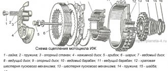
What can we say about the device? The clutch of the Soviet-style Ant scooter consists of several elements. Namely:
- spacer sleeve;
- chains;
- clutch drive drum;
- long rod;
- ball;
- short rod;
- clutch driven drum;
- clutch discs;
- left crankcase cover;
- paper gasket;
- lock washer;
- springs;
- spring pin;
- asterisks.
Having a rough understanding of the device, the principle of operation and what kind of circuit is provided here, it will be much easier to understand the repair and adjustment of the clutch assembly on a Soviet scooter.
What pressure should be in the tires of an Ant scooter?
During the times of the former USSR, although the “Ant” caused a lot of trouble for its owners, people bought it and even drove it. Where were the people supposed to go? Those who built the house, those who ran the farm, brought their last money to the store and drove with one hand, and with the other, wiping away tears, exploited these Soviet scabs.
The design for those years is much better than many modern designs
If the factory design is not comme il faut, numerous collective farm tuning studios offer their variations. In the same place, as additional options you can order a trailed and automatic chain tensioner...
Assembly
I bought this main bearing. It seems to be our production. There are Chinese analogues in stores - they are more expensive, but I don’t know what their quality is... I try to buy something that may not be of such super-duper quality, but at least one that has been proven over the years.
The quality of production is such that there is essentially nothing to complain about. The price is quite reasonable - 350 rubles.
We press the inner race of the main bearing onto the right crankshaft journal. External - screw the stator flange of the dynostarter and press it into the crankcase until it rests against the flange.
We install the oil seal, retaining ring and main bearing into the left half of the crankcase. I'm installing a new main bearing. It is closed, but it doesn’t matter: we open it, wash out the factory grease and install it in the crankcase.
Lubricate all bearings and working edges of oil seals with clean engine oil. And very carefully, so as not to accidentally wrap the edge of the oil seal - insert the crankshaft into the left half of the crankcase, and knock out the crankcase guides by 5-6mm.
We degrease the crankcase connector, install a new gasket and install the second half of the crankcase.
Tighten the bolts and immediately so that nothing gets into the crankcase -. I'm installing a new piston, cylinder head and reed valve body. The piston one, like everything else, is of no particular origin - most likely Rostov, but clearly not Chinese. I didn’t want to get involved with this counterfeit, but the owner didn’t want to wait until they bore the cylinder and put a liner in the cylinder head and insisted on buying it. You see the prices for spare parts - it’s up to you to decide whether to contact this new product or not.
We install the second main bearing into the crankcase and secure it with a retaining ring.
It's no secret that the engineers of the Tula plant have created equipment with which the average owner has to feel like a mechanic. To this day, having found another problem, Ant’s owner has to pick up a tool, remembering the would-be engineers. One of the main problems is the engine of the Ant scooter, which is repaired in most cases of breakdowns.
general information
The Soviet cargo scooter has a reliable metal trike, made in the form of a platform with a tailgate. Ant's trike is quite roomy. The platform's carrying capacity is 250 kilograms, which allows the Ant scooter to be actively used for household needs. Thus, a cargo scooter allows you to transport:
Motor vehicles are distinguished by maneuverability and unpretentiousness. In the garage, the Ant scooter takes up about the same space as a bulky motorized vehicle with a sidecar. Ant's turning radius is about 3.5 meters.
Characteristics of the Ant scooter
In winter, a cargo moped operates using a mixture of M6/3-10G/1 engine oil and A-76 gasoline, and in summer it requires the M8B grade.
If we compare the Ant scooter with a sidecar motorcycle, then in terms of operational fuel consumption the advantages will be on the side of the former. A cargo moped “eats” 8 liters/100 kilometers. It is also much lighter than a motorcycle with a sidecar - its weight is 240 kilograms.
Build errors
In most cases, the right main bearing of the crankshaft fails due to an assembly error almost in the first season after repair. The engine that we are now repairing is no exception. The bearing has practically crumbled and in any case needs to be replaced with a new one.
The mistake is that when installing the flange on which the dynostarter stator is attached, the oil channel through which lubricant flows to the main bearing and oil seal is sealed.
To ensure that the main bearing lasts at least several seasons, cut the gasket under the flange a little along the contour of the oil channel and when you put the flange in place, do not smear anything with sealant there.
Photo report: Replacing the rear chain of an Alpha moped
Torque chain transmission is always a problem. But low cost, ease of maintenance, coupled with low weight, and for a motorcycle - weight is a very significant parameter - outweigh all the disadvantages and the chain drive of the rear wheel, just like many years ago, is dominant in the motorcycle industry. And we are unlikely to get away from this in the coming decades.
As already said: the chain is always a problem. The infection is spreading and nothing can be done about it. And if only it drags on, it begins to eat the teeth of the stars and if it is not replaced with a new one in time, then it will literally eat the stars in one season.
Without going into theory, let's consider a classic case: the chain has stretched and requires urgent replacement. If you look closely at the picture, you will see that the chain rollers do not fit into the sprocket teeth. As a result, the chain rollers hit the sprocket teeth and eat it up literally in one season.
Some especially gifted people manage to cut their own exclusive teeth on such sprockets using a grinder. But we won’t suffer from such garbage today, but we’ll buy a new driving star (the driven one is still alive, it’s good for a couple of seasons), a chain and do everything like a human being, and not like a collective farm.
When choosing a new chain, consider the width and number of teeth on your moped's sprockets. Chains for Alpha come in different widths and lengths: some are wide, some are narrow, some are long, some are short. We will use a wide 428 for Z13 Z41 sprockets, and which one you will use depends only on your sprockets and preferences.
We install the pin on the footrest, if you have one, of course.
We remove the casings, the drive sprocket cover, unscrew the rear wheel/rear sprocket axle nut, and loosen the tension chains on both sides.
We look for a lock on the chain, unfasten it and remove the old chain. For tusks, the chain is always riveted tightly and in this regard I was unlucky: I had to go for the grinder B-)…
We push the wheel along the rear pendulum as far forward as possible, throw on a new chain, and fasten the lock. To prevent the lock from unfastening while moving, we place the latch so that its cut faces in the opposite direction from the direction of its movement. To avoid getting confused, do this: turn the wheel so that the lock is on top of the pendulum and fasten the latch with the cut towards the rear wheel.
We lightly tighten the nuts of the sprocket/rear axle, remove the stub from the step, pump the rear suspension several times and slowly begin to tighten the chain according to approximately the following principle: tighten the chain a little and immediately measure with a ruler how the wheel is.
If the distance from the wheel to the pendulum on one side is significantly less or greater than on the other, we calibrate the position of the wheel with the required tensioner. In this way, in fits and starts, we pull the chain to the desired condition.
We pull the chain until it sag by 1-1.5 cm. This will be quite enough. After everything has been done, tighten the axle nuts and make sure to adjust the rear brakes. Never forget about the brakes, otherwise you’ll end up slamming into a trash can or a similar deer.
Malfunctions
Due to the fact that when starting the engine, the force from the kickstarter is directly transmitted to the first gear gear, the bushing with which the gear rests on the input shaft wears out and wears out so that the gear simply begins to dangle on the shaft
- Before assembly, we put the first gear gear in its place and try to swing it. If the gear is loose, replace it with a new one, or, if you have experience in this area, change only the bushing and leave the gear
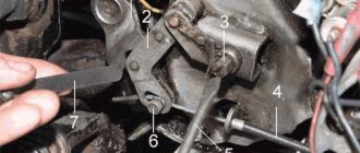
- The second typical malfunction is due to the fact that the roller that fixes the copy shaft does not always work exactly on the “daisy”, but often jumps off it and instead of the roller, the “daisy” is fixed by the locking bar, as in my case. Such a malfunction leads to the fact that the gears begin to knock out, fail to engage or jump over one
Notice how the contact with the “chamomile” erased the bar and cut off one tendril of the cotter pin
- This malfunction can be eliminated very easily and simply: place the retainer bar along with its spring on the gearshift shaft and insert the shaft into the crankcase. Then insert the copy shaft there and turn it several times and see where the roller runs.
- If the roller does not run along the “daisy”, use pliers to bend the clamp bar in the desired direction so that the roller runs strictly along the “daisy” of the copy shaft
Correct roller position
All other malfunctions that this gearbox suffers from are typical for Soviet-made motorcycle gearboxes and consist of wear on the working edges of the cam clutches, gear teeth and gear shift forks
For clarity, I dug out for you from a pile of rubbish the input shaft with truly extreme wear on the teeth of the first gear drive gear. Its tooth wear is about 1mm. It seems that the only thing they were doing with this scooter was that they were “pulling GAZelles”... Such wear on the gears is critical and the shaft is not subject to further use
No matter how many times I went through TMZ engines, I never came across gears with worn cam couplings, and I went through a couple of cars of them, if not more... I dare to suggest that wear on cam couplings is not a typical problem with TMZ engines, unlike Izh, Zid and other engines
The gear claw couplings should be in approximately this condition. Unfortunately, I was never able to find gears with worn couplings even in a pile of rubbish. So there's nothing to show
All gearboxes, including this one, suffer from wear on the working surfaces of the forks. If the wear is no more than about.5mm, then this is quite acceptable
Maintenance and repair
Due to its low weight, this moped, if necessary, can be “put on its side” even alone. Also, given that Ant disc wheels consist of 2 halves bolted together, replacing a damaged tire is quite simple. To connect the tube and the spare tire, it is necessary to separate the parts of the removed wheel.
Motor scooter repair Ant
Tools
In order to properly repair a Soviet moped, you will need the following tools:
Diagnostics
The Ant scooter must undergo regular maintenance. This is necessary for two reasons:
Homemade auto moto
In the meantime, I took Ant for repairs and installed a Lifan 188f engine (400 cm3, 13 hp). Would it be interesting to create one on the forum, although I don’t know in which section))?
Yes, does anyone know why the steering wheel chatters at any speed? The bushings seem to be alive, there are no backlashes...
Re: Shket-2 or bierkisten in Russian
- Quote
Post by vovka » Wed Jul 08, 2015 6:11 pm
Re: Shket-2 or bierkisten in Russian
- Quote
Post by Vasilev » Wed Jul 08, 2015 11:57 pm
Re: Shket-2 or bierkisten in Russian
- Quote
Post by ilya38 » Thu Jul 09, 2015 4:47 am
Motor scooters Ant Repair manual + parts catalog
CONTENTS OF THE BOOK REPAIR MANUAL MOTOR SCOOTERS ANT + PARTS CATALOG
Introduction 3 Chapter 1. Brief information and technical characteristics 5 Technical characteristics of Ant scooters 8 Motor scooter controls 10 Maintenance of the throttle handle 17 Control cables 18 Maintenance and repair of control cables 18 Maintenance of the scooter 20 Chapter 2. Power unit, engine 22 Removal power unit 22 Disassembling the power unit 26 Inspection and sorting of parts after disassembly 27 Engine 27 Crank mechanism 31 Cylinder and cylinder head 31 Piston 34 Piston rings 35 Piston pin 38 Connecting rod 39 Crankshaft 41 Connecting rod bearing rollers 44 Crank pin 44 Crank pins chat shaft 46 Carter 47 Lubrication system 51 Lubricants 51 Cooling system 52 Possible engine malfunctions and methods for eliminating them 55 Chapter 3. Power and exhaust system 57 Gas valve 58 Carburetor 59 Carburetor K-28G 59 Carburetor K-36G 62 Operating principle of the carburetor K-36G 65 Disassembly and carburetor assembly 66 Carburetor repair 67 Carburetor adjustment 68 K-62G carburetor 69 Removing and disassembling the carburetor 72 Carburetor adjustment 72 Checking the tightness of the carburetor mount 72 Setting the fuel level in the float chamber 72 Adjusting the idle speed 73 Adjusting the position of the metering needle 74 Carburetor K-65 G 75 Design and the principle of operation of the K-65G carburetor 76 System for supplying and maintaining a constant fuel level 77 Main metering system 77 Idle system 78 Engine starting and warming up system 78 Float quencher 79 Removing and disassembling the carburetor 79 Installing the carburetor 79 Adjusting the K-65G carburetor 80 Setting the fuel level 80 Idle speed adjustment 80 Adjustment of the metering needle position 81 Air cleaner 81 Exhaust system 83 Basic carburetor malfunctions and methods for eliminating them 86 Chapter 4. Transmission 88 Forward gear 88 Motor chain 89 Clutch 89 Clutch adjustment 92 Clutch malfunctions 92 Clutch repair 93 Clutch drive drum 93 Discs clutch 94 Clutch spring 94 Clutch release rods 95 Gearbox 96 Gearbox operation 99 Gear shift mechanism 101 Gearbox maintenance 102 Oil change 102 Gearbox disassembly 102 Gearbox repair 103 Gearbox assembly 10З Starting mechanism of the Ant scooter 106 Intermediate gear 107 Lubrication intermediate drive chains 109 Adjusting the tension of the intermediate drive chain 109 Main gear and differential 110 Maintenance of the final drive and differential 116 Disassembling the final drive and differential gearbox 116 Repairing the final drive and differential 116 Differential cups 116 Planetaries 118 Final drive axle gears 118 Differential assembly 118 Gearbox assembly main drive 118 Drive axle 120 Driven axle 120 Rear wheel drive 121 Repair of the cardan joint 124 Maintenance of the cardan drive 124 Chapter 5. Chassis 125 Frame 125 Front suspension 128 Spring-hydraulic shock absorber 132 Rear suspension 134 Maintenance of the front suspension 138 Maintenance of the rear , pendants 138 Brakes 138 Maintenance and repair of the brake system 143 Replacing brake linings 144 Wheels and tires 146 Chapter 6. Electrical equipment 148 Battery 150 Electrical circuit for powering the battery charge warning lamp (red) 152 Main types of battery malfunctions 153 Dynastarter 154 Dynastarter maintenance 157 Regulator relay 160 Checking the starter relay 164 Checking the reverse current relay 165 Procedure for checking the VSU-10 and D-104-20 diodes that regulate the reverse current in the relay-regulator 2903.3702 165 Checking the voltage regulator 166 Ignition system 168 Ignition coil 168 Breaker 169 Adjusting the gap in the breaker 170 Capacitor 170 High-voltage wire 171 Spark plug 171 Setting the ignition timing 172 Adjusting the ignition timing for scooters of the TGA and Ant family 172 Adjusting the ignition timing for scooters of the Ant-2 family 173 Lighting and signaling devices 175. Headlight 175 Electrical power supply circuit for low and high beam lamps 175 Electrical power supply circuit for the brake light lamp 175 Horn 175 Tail light 176 Direction indicators, indicator breaker 176 Applications 178 Literature 186
BUY BOOK REPAIR MANUAL FOR SCOOTERS ANT + PARTS CATALOG
Source
How to adjust the ignition on an ant
The electrical circuit of the Ant scooter is quite simple and does not contain heavy components. It is used for three main tasks:
- Ignition of the air-fuel mixture in the cylinder. Due to this action, the piston moves, transmitting torque to the flywheel.
- Starting a cold and warm engine.
- Supplying current to lighting fixtures and signal signs (turn signals, parking lights, brake lights).
Ant's electrical equipment is a system with one wire, and the second is the body of the moped itself. All equipment has excellent insulation, eliminating the possibility of short circuits and harm to the driver. Maintenance of electronics on a motorcycle consists only of regular cleaning of the terminals. However, to find the problem, you need to keep a tester at hand. He will accurately determine the problem that is preventing the operation of electrical equipment.
Ignition installation
Installing the ignition on an Ant scooter, as on any motorcycle with a single-cylinder engine and a battery ignition system, does not require special knowledge or effort. All you need is very thin paper, a narrow rod and a set of keys. So, how to set the ignition on an Ant scooter:
- Remove the spark plug and set the piston to top dead center (hereinafter referred to as TDC).
- Insert a rod through the hole from which the spark plug was removed and press it against the piston head. Make a notch at a length of 4.5-5 mm
- Close the breaker contacts when the piston is at TDC. Place paper between them and pinch.
- Turn the crankshaft counterclockwise as slowly as possible and pull the piece of paper at the same time.
- When the paper is released when the piston is lowered to the depth of the mark made, the ignition will be set correctly.
We recommend reading:
How to set the ignition timing on an Ant scooter so that the engine runs and starts well?
In order for any internal combustion engine to start and “work well” (and it is the Internal Combustion Engine installed on your scooter), you need to supply fuel to it and then ignite it at the right moment. Moreover, the engine does not work in only two cases:
- or there is nothing to burn...
- or there is nothing to set on fire...
You are interested in the second case. So:
The work of any internal combustion engine is to convert the reciprocating motion of the piston into the rotational motion of the shaft. This transformation occurs with the help of a crank mechanism (CSM). How this transformation occurs is known from the elementary school “Physics” course.
For “good” operation of the internal combustion engine, all the fuel must burn in the cylinder within a very specific time - while the shaft rotates at a certain angle. Like the picture below:
In order for the fuel to burn at the necessary moments of movement of the piston along the cylinder, it must be ignited in a timely manner. In the Ant engine, the fuel is ignited by a spark in a spark gap called a spark plug. The ignition system, consisting of the following elements, organizes the formation of a spark between the electrodes of the spark plug:
- spark plug;
- ignition coil with capacitor;
- current breaker;
- current source (battery and generator);
- connecting wires.
How the listed elements work and interact with each other can be read in the same “Physics Primer” for elementary school. Here I will only remind you that a spark in the spark plug occurs at the moment the breaker contacts open. It is this moment in time that must be captured when setting the ignition timing. “Physically” this is quite simple to do. When the current source is turned off, we clamp the strip of paper with the contacts of the breaker. Smoothly turning the engine power take-off shaft with one hand, we pull our paper strip with the other. When the contacts release the strip, at that moment the event we need will occur in the spark plug.
Engine assembly
Unlike a dynastarter, repairing an Ant scooter engine with your own hands is difficult to do according to the operating book. Therefore, it is worth seeking the advice of experienced motorcycle owners. Most often, the engine has to be disassembled when there are problems with the clutch mechanisms, the operation of the gearbox, as well as wear on the crankshaft, bearings or oil seals. The most important rule is not to be afraid to disassemble the engine yourself. Using these instructions, disassembling and assembling the engine of the Ant scooter will not be difficult.
So, the procedure for disassembling the engine:
You can see how to assemble an Ant scooter engine in more detail in the visual video at the end of the article. The essence of assembly is in the reverse order, but it is important to tighten the parts with a certain force and synchronize the parts with the marks. Under no circumstances should you assemble an engine without detailed instructions written by the manufacturer.
With frequent breakdowns, owners think about what engine can be installed on the Ant scooter. Instead of the original motor, you can use Chinese analog motors
. Since the Ant has many copies in Asian countries, replacing the engine can be a great option to save money in case of irreversible damage. True, you will have to make the fastenings yourself and, in some cases, remake the bridge for the left-hand arrangement of the chain. This is not very difficult, considering that the Tula plant provided for the possibility of rearranging the bridge.