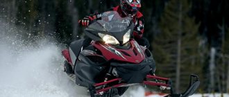
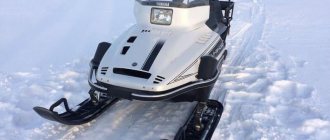
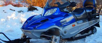
Not all equipment is able to function effectively in Russian winter conditions. And if operation is needed in Siberian regions, then only a few vehicles remain that can operate in such a climate. One such example is the famous Yamaha Biking 540 snowmobile. This Japanese snowmobile has been firmly established on the market since 1988, having undergone only minor changes.
We will begin the description of the Yamaha Viking 540 snowmobile with the fourth model, since there is no point in considering earlier options. But first, let's go a little deeper into history.
Snowmobile history
The Yamaha Viking 540 was first released in 1988. It immediately gained fame as an indestructible vehicle, ideal for fishing, hunting and working in northern conditions. In 1994, a minor redesign was made to the front end and seat. The second generation lasted on the market until 1998. The third generation, released in 2001, received new skis and a track. The fourth generation Yamaha Viking 540 was launched in 2012. It did not receive anything significantly new, except for improved skis. Tough Pro appeared in 2013? light version of the snowmobile. [ads-pc-1]
The lineup
At the moment, the Yamaha Viking 540 is available in five different versions:
- Tough Pro 15;
- Limited 15;
- Limited 16;
- 15;
- 16.
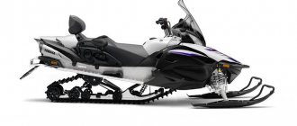
Especially in this series I would like to note the Limited and Tough Pro models. The difference between the first one is an exclusive white paint job, wide skis, an improved track and, which is very useful when towing,? there are rear view mirrors. It also has a tachometer. This model is designed primarily for the transportation of goods.
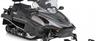
The Tough Pro model is specially designed for the harsh winter conditions of Russia. Roughly speaking, this option? this is the same Yamaha Viking 540, from which everything unnecessary has been cut off. And its price is significantly lower than the entire line; only children's models are cheaper than it. Another distinctive feature is that it is refueled not with simple fuel, but with a mixture of gasoline and oil. So, according to the Japanese, the engine is easier to start.
Installation of temperature sensors in the engine head, general recommendations
Installing temperature sensors in engine heads is not difficult. To install sensors without removing the cylinder heads from the engine, it is necessary to determine in advance where the recesses will be prepared. For example, by examining an analogue head in a store. When drilling a recess for the sensor, use a drill with a diameter 2-3 hundred parts larger than the diameter of the sensor and do not drill through the head! The minimum is considered to be a recess in which the sensor is placed at a height of at least 7 mm (applies to a kit sensor). In this case, a cambric should be placed on the protruding part of the sensors, depriving the sensors of airflow. The ideal option is that the sensors are completely immersed in the body of the head and do not protrude outward. The advantage of this installation is that you install it once and forget it! There is no need to dismantle the sensors in the future, for example when replacing spark plugs, which means there is no risk of damage. The closer the sensors are located to the center of the heads, the more accurate the readings and the faster their change. We do not recommend installing sensors in the engine head, on the exhaust manifold side - the temperature will be too high.
The thickness of the head where the spark plug is mounted is usually equal to the length of the spark plug thread. Quite often, a recess for the sensor is drilled near the spark plug, so that the spark plug is located between the sensor and the fan. This method is correct - the sensor is as close as possible to the center of the head. If you use this method, make sure that when installing the spark plug, the key does not touch the sensor.
Before installing the sensor in the recess, the recess must be filled with KPT 8 thermal paste or similar. Thermal paste fills air gaps and promotes 99.9% of heat transfer from the head to the sensor. After installing the sensor, the edges of the recesses are slightly deformed by the core (it is not permissible to deform the sensors). This prevents the sensor from falling out.
Installing a temperature sensor in the head of a Buran snowmobile
In our opinion, this is not the best place for installation. With this installation of the sensor (from the exhaust side), the readings will be higher. It is clear that exhaust gases have significant temperatures. In addition, the sensor wires were left unprotected and very soon, due to vibration, they would lose their insulation from being closed. About how the kit works Moto thermometer on the Buran snowmobile
Installing sensors in the engine head of a Taiga snowmobile
The sensor installation location is selected in the stiffening rib of the engine head, running crosswise, from stud to stud. The thickness of the metal in this place is about 26 mm
Installing a temperature sensor on the Lynx snowmobile, similar to the installation on the Taiga snowmobile
Attention! On 2-cylinder engines, temperature sensors should not be installed, say only at the right studs (as in the photo below). This will lead to significant differences in readings, up to 30 degrees Celsius. The reason is quite simple - the installation location of one sensor is close to the fan and is very cool, the second sensor is installed almost at the epicenter of the heat. To avoid this effect, the sensors should have been positioned differently - the sensor of the left cylinder should be installed at the right stud, the sensor of the right cylinder - at the left, that is, opposite each other at the inner studs
Installation of temperature sensors in the Lynx snowmobile engine head is also possible in the technological holes available on the engine cylinders. As a rule, the holes need to be deepened
Operation in wet environments*
It is noted that when operating devices on equipment that is frequently exposed to moisture, oxidation of printed circuit boards may occur, followed by failure of electronic parts. This situation is faced by users who daily operate equipment in the cold - warm garage mode, or on the water (powerboats). It is quite easy to protect the device from moisture. It is necessary to cover the printed circuit boards with a protective compound that prevents exposure to moisture. Radio stores have a wide range of such products. Before applying the protective layer, wiping with pure alcohol is useful.
Don't forget to thank the author by clicking the rating button at the top of the page, or by posting a link to the article on the Internet. Thank you
Specifications
Since this snowmobile is positioned as a utilitarian one, everything was given for the sake of efficiency and reliability. The technical characteristics of the Yamaha Viking 540 are as follows:
- engine ? two-cylinder, two-stroke with a displacement of 535 cc. CM air-cooled;
- transmission? CVT with high and low gears, reverse gear;
- brakes? mechanical, disk;
- suspension travel? 150 mm front and 385 mm rear;
- dimensions? 1355 mm height, 3055 mm length, 1190 mm width;
- tank capacity? 31 l;
- headlights? halogen, power 60 watts.
There are no differences among the models in terms of technical characteristics. [ads-pc-2]
Operation in winter conditions
The Yamaha Viking snowmobile is specially designed for work and recreation in harsh winter conditions. It holds a straight line perfectly at cruising speed and handles road unevenness well. This is nothing new for touring snowmobiles, but it was hard to expect for a utilitarian line. New skis and shock absorbers (gas-filled) improved the already excellent qualities of the snowmobile, significantly eliminating yaw on uneven surfaces.
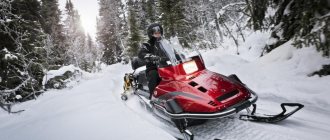
Yamaha is perfect for hunters and fishermen due to its increased cross-country ability. According to them, a snowmobile passes where a person falls waist-deep. And given the state of the snowmobile infrastructure and the availability of trails, this quality is truly outstanding.
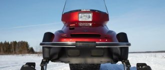
The device also copes with the transportation of cargo and passengers with a bang. Thanks to the low seating position and confident grip, the chances of flipping over on a sharp turn are close to zero.
About temperature sensors, tuning and repair of snowmobiles!
Hello! You can buy CITD 3 and CITD 4 in the Yetipro.ru store, which is what we did. Having gutted the mailbox and sharing the contents with a friend, we agreed to install the devices in the evening, especially since it was a Friday. At the end of the article there will be a VIDEO of the operation of sensors on a SNOWMOBILE!
And now evening has come! The Yamaha snowmobile was driven into a warm garage, with a temperature of 0 C, but not outside, to install the digital temperature indicator CITD 3. It took about 10 minutes to study the installation instructions, then we started. The work was carried out together, with a friend, taking turns driving their snowmobiles
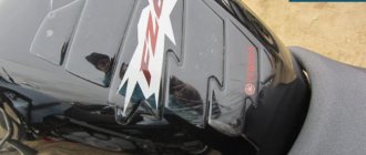
Having assessed the snowmobile panel and the space under it, the installation location of the TsITD 3
Then, we began to make a cut along the intended contour. Why was a HITACHI brand screwdriver used - another one will not be suitable for these purposes))
At the work stage, the snowmobile panel began to look like this
Then a sharp knife with a narrow blade was used. The plastic of the Yamaha VK 540 panel turned out to be very soft and cut easily
And so we got a neat cutout. Nearby we drilled a hole for the button for reading the outdoor temperature sensor
Having inserted the measuring unit into the hole, we found that the body of the device rests against the mount for the reverse sound signal
Having thought about this event, the sound signal was unscrewed from its mounting point
Using a metal blade, the fastening was mercilessly sawed off
And a hole was drilled in the hood of the snowmobile for a new location for installing the tweeter
The measuring unit CITD 3 and the button for outdoor temperature readings were installed, and we began laying the device’s wires. The wires of the device are thick, with a good cross-section, which instills confidence. We fastened the snowmobile wiring directly along the spit using plastic ties. The CITD 3 kit includes two plastic ties. This quantity is not enough, it is better to stock up on them in advance, or use improvised materials, such as electrical tape. Outdoor temperature sensor CITD 3 , mounted on the bumper, in the area of the left hinge of the snowmobile hood
Having extended the sensor wires to the engine, we were faced with the need to remove the top cover of the airflow casing. Of course, it was possible to insert temperature sensors through the holes in the spark plug wells, but it doesn’t look pretty. And unscrewing the 4 bolts securing the cover is a matter of seconds.
After unscrewing the bolts, shake and pull the cover towards the left side of the snowmobile. It comes off easily. We removed the spark plugs and used pliers to cut the O-rings off of them. The temperature sensors were placed in the spark plug wells in such a way that the sensor wires ran with less bends. The insulation of the temperature sensor wire is thermally resistant and does not melt due to the temperature of the cylinders. Screw the candles into place
Reinstalled the air hood cover
Having finished with the mechanical part, we started connecting the device. As stated in the instructions, CITD 3 can operate on both alternating and direct voltage and it does not matter whether the snowmobile has a battery or not. We connected the plus of the device to the speedometer light bulb, and the minus to ground. (NOTE on Yamaha Viking snowmobiles, without a tachometer, there are two free wires in the headlight area, we had them in black and blue. You cannot connect the CITD or anything else to them - it will burn out. These wires are intended for connecting the tachometer, the voltage is on They are pulsed and increase depending on engine speed.)
On a friend’s snowmobile, also a Yamaha VK 540, but with a battery, the device was connected through the ignition switch. In a nutshell it looks like this! There is a brown wire going to the ignition switch (at least, this was the color on both snowmobiles), we connect the positive wire of the device to it. So we got the following operation of the CITD: the ignition is turned off - the device does not work, the key is on - the device works, the key is in the electric work position. starter - the device does not work, the engine starts and the key is released - the device works. What does this give? The battery provides stable voltage in all modes of engine operation - it absorbs voltage surges and compensates for dips at low speeds, providing stable power to the device, which is the key to long-term performance.
Don't forget to thank the author by clicking the rating button at the top of the page, or by posting a link to the article on the Internet. Thank you
Temperature sensor CITD 3 works on a Yamaha VK-540
Malfunctions and maintainability
Most often, owners of a Yamaha Viking 540, having ridden it for more than 5,000 km, rarely encounter problems or repairs. If there is any malfunction, it occurs either due to a manufacturing defect or damage.
The most common breakdowns:
- faulty spark plugs? During operation, one of the spark plugs may fail, which greatly affects the power of the snowmobile. This can be corrected by purchasing and replacing a spark plug;
- cracks in plastic tubes? It’s no secret that plastic becomes brittle in extreme cold. Therefore, these parts are considered consumables and are replaced when worn out;
- oil hunger? a manufacturing defect that occurs quite often. If it is not detected in advance, then it will no longer be possible to start the snowmobile. Self-repair is not possible.
There are also other breakdowns, but these three above? most frequent. [ads-pc-3]
Recommendations for installing temperature sensors
When mounting the device body into the snowmobile's instrument panel, keep in mind: the installation location should always be in front of your eyes, without obstructing your view, with little exposure to air turbulence - when moving, the snowmobile raises snow dust, which settles differently in different parts of the snowmobile. When cutting out a space for the body in a snowmobile panel, remember the proverb “measure 7 times, cut once.” The laying of wires is carried out using frequent fixing laying or the wires should be placed in additional protection such as a cambric. The insulation of the wires is negligible; vibration frays, which leads to a short circuit. When extending the sensor wires (if necessary), take into account that the temperature sensor is polar and make the connection in accordance with the polarity. The connections should be soldered and insulated; wires should not be mounted on twisted wires. It is possible to do without soldering by using electric wires to connect them. automotive type connectors. In the future, such a connection is more convenient for repair work, as it allows the components of the device to be easily removable. Note! The sensor wires are heat-resistant - they can withstand the operating temperature of the engine, but not the exhaust manifold. They can be extended using any wire, without exceeding the resistance of each wire of 5 Ohms. The kit sensor itself is sealed and can be used to monitor the engine temperature using oil or coolant temperature or to measure the ambient air temperature, like an outdoor thermometer.
Regardless of the method of installing the sensors, it is necessary to isolate them from the incoming air flow - otherwise the readings will be underestimated, since part of the temperature will be blown away by the cooling flow. The sensor or adapter tube can be insulated with heat-shrinkable tubing, casing, cotton tape, or auto sealant.
Power supply - connect temperature sensors in accordance with the installation manual Kit kit. Do not connect power to the wires, just maybe. Check the voltage at the location of the planned connection with a special device, at different engine speeds. Remember that the device is not designed to be connected directly to the engine magneto, bypassing the standard voltage stabilizer. Also, it should not be connected to the old type of rectifier devices of Russian technology such as VU.
The average operating temperature of a serviceable two-cylinder engine, under light and medium operating conditions, is 140 - 150 degrees Celsius. The discrepancies in the temperature readings of the left and right cylinders, on new - working engines, under different loads, range from 2 to 25 ° C. During normal operation 8 -12°C. The temperature spread between the cylinders may vary depending on the speed. If the temperature spread across the cylinders approaches 30°C, this usually indicates a poor technical condition of the engine. Be sure to check: the condition of the spark plugs and the settings of the ignition system, fuel supply, engine tightness, cooling system.
Installing sensors under the spark plug has undoubted advantages, which include: if the engine is under warranty, such installation will not lead to its loss (requires clarification from the dealer); installation method is less time-consuming; certain accuracy of readings - the sensor is located in close proximity to the epicenter of combustion, it is not affected by heat dissipation in various parts of the engine - with such an installation, when taking readings, it is possible to rely on the generally accepted pattern of 180 - 200 degrees (in accordance with the operating instructions for a particular technical means).