MY MOTORCYCLE
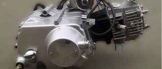
Scooters can now be found everywhere; this vehicle is no longer a curiosity. But not everyone knows how to repair an engine, by the way, I’m also one of them, I had a Suzuki scooter. When it was necessary to repair something, I took him to the “uncle master” and he straightened everything out for me. Now I want to give you (and myself) an example of repairing a Minarelli engine (an engine of this color is mainly found on all small-capacity scooters).
Over its long history, the Minarelli two-stroke engine has become perhaps the most widespread in the world: 50- and 100-cc models from Yamaha, Italjet, Aprilia, Malaguti, Benelli are built on it, and the Chinese, without further ado, copied it, which only added to the latest popularity. Using the example of the popular Yamaha Jog scooter, we will show how to properly capitalize a Minarelli.
There are few indications for overhauling a two-stroke engine: a rumble in time with the crankshaft revolutions means “tired” upper and lower connecting rod bearings, a dull noise means the death of the crankshaft main bearings. “Jumping” idle and inadequate response to the throttle when the carburetor is correctly configured – crankcase depressurization. The engine can suck air between the crankcase halves, and (which happens more often) through the crankshaft seals.
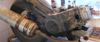
When the symptoms described appear, the first thing you need to do is figure out what exactly the problem is. In principle, you can damage the motor without “rolling out” it, but this is not very convenient. It’s good to disassemble, and most importantly, to assemble the motor only on a workbench, so let’s start by removing the engine (photo 1). To do this, you need to disconnect the rear brake cable (if the brake is a disc brake, it is most convenient to remove the caliper without disconnecting it from the hose), the carburetor, disconnect all the electrical wiring connectors and the oil pump hose (oil will flow out of it, so it is better to put it in a bottle or squeeze).
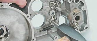
We unscrew the lower bolt of the shock absorber, remove the motor mounting axis and “roll out” the block with the wheel (photo 2). We begin disassembly by dismantling all the attachments: muffler, cooling casings, wheel, center stand and variator cover. We unscrew the transmission, remove the starter and overrunning clutch. The clutch has a needle bearing and three spring-loaded rollers, so carefully, so as not to shake out small parts, we put it aside (photo 3). On the right, remove the cooling impeller and magneto.
To remove the magneto, special pullers are sold, but before purchasing one, you need to take into account that Minarelli generators come in different varieties. On our “experimental” ignition 5VM, the magneto is removed by the threaded holes securing the impeller, but on most engines with ignition 2JA, the magneto has a thread for a puller (photos 4 and 5).
Having removed the magneto, unscrew the board with the generator stator and remove the oil pump. Having pulled out the locking rings, remove the oil pump drive. Check the condition of the fit under the generator bell key on the crankshaft. Now, holding the end of the crankshaft with your hand, it is easy to check the presence of vertical and horizontal play in the main bearings and see the condition of the seals (photo 6). If the seals look alive, but the engine still sucks in air, it will have to be “inflated”, but more on that later (photo 30).
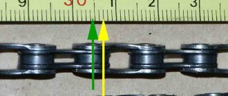
Crosswise, gradually loosen the nuts and unscrew them (photo 8). We remove the “head” and the cylinder itself - now you can see the condition of the “mirror” on the cylinder, visually assess its wear and check for scratches on it. Ring wear can be assessed by measuring the gap in the lock. To do this, you need to insert the compression ring inside the cylinder, use the piston to align it perpendicularly in the area of the lower limit of the working stroke and measure the gap in the lock with a feeler gauge, the norm is 0.1–0.2 mm.
At a distance of 5 mm from the edge of the skirt, across the piston pin axis, we measure the piston diameter, tolerance from 39.957 mm to 39.977 mm. Even if the piston and rings are in order, and the cylinder seems “alive”, it is not superfluous to check its production in the area of the piston skirt near BDC. To do this, insert a compression ring into the cylinder and align it with the piston. If gaps are visible in the light, the cylinder will have to be bored or replaced.
In our case, the cylinder is in perfect order, so it will go for assembly. To check the condition of the upper connecting rod bearing, simply grab the connecting rod with one hand and the piston with the other and check for radial play. If there is play, you will have to replace the needle bearing and piston pin. With the lower bearing it is more difficult: the pin of the lower connecting rod head is pressed between the crankshaft cheeks and cannot be repaired.
We take the connecting rod and check for radial and axial play. Axial play is not critical, but radial play is an indication for replacing the crankshaft and connecting rod assembly. On our engine, the crankshaft has expired and will have to be replaced (photo 7). Remove the retaining ring from the piston and pull out the pin. Using ordinary automotive feeler gauges, we measure the distance between the crankshaft cheek and the crankcase wall: 0.75 mm on one side and 1.45 mm on the other (photo 9). A crooked installation in our case caused the premature death of the bearing.
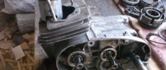
The engine will have to be “chopped”. To begin with, thoroughly wash the outside of the engine (photo 10). We remove the intake manifold and take out the “house” of the reed valve. We move the locking ring on the motor mounting axis and knock it out by a third with light blows (photo 11). Everything is ready - let's proceed to the most difficult and important part of the work. Crosswise in several stages we loosen and unscrew the bolts holding the crankcase halves together. Using a gas burner or a technical hair dryer, we heat the crankcase (no more than 200 °C!), install the puller and “pull out” the smaller half.
There are some pitfalls here too. In addition to the bolts, the halves are held in place by two guide bushings, and if there are no problems with the upper one, the lower one, due to its location, turns sour. When pulled apart, it causes a misalignment, so fill the joint with penetrating lubricant and carefully monitor its exit from the groove. The misalignment of the halves when opening threatens to bend the crankshaft. The same goes for disassembling the engine without a puller: you can do without it, but the crankshaft will most likely have to be thrown out.
Before starting work, it is important to have not only a set of tools and pullers, but also the necessary spare parts. At a minimum, new main bearings and seals. Unlike a four-stroke engine, where oil will simply ooze through a “tired” oil seal, a “two-stroke” will suck air and, accordingly, work incorrectly or not work at all. New cylinder gaskets or a piece of paronite of suitable thickness will not be superfluous. You also won’t be able to do without two or three bottles of carburetor cleaner for cleaning and degreasing parts, a liter of engine oil and grease. You shouldn’t skimp on sealant either – petrol- and heat-resistant, preferably rubber-based. Coolant and gas cylinders for a small burner or a technical hair dryer will come in handy. As for the tools, everything is not so simple: the usual set will have to be supplemented with a torque wrench, feeler gauges (simple automotive ones will do) and a rubber mallet. Anyone who takes a fundamental approach to engine overhaul will have to buy a generator puller, a regular bearing puller, as well as special devices for pressing out and pressing in the crankshaft.
If a new one has already been purchased, and the old one is completely useless, disassembly without a puller is acceptable (photos 12 and 13). After removing the small half of the crankcase, we perform a similar operation with the large one: heat it up and press out the crankshaft. If you only need to replace the main bearings, use a puller to pull them off the crankshaft. It is important to remember: if you plan to install the crankshaft backwards, you need to check it for runout (photo 14), it should not exceed 0.03 mm.
We carefully wash the released crankcase castings (photo 17), remove the remaining gaskets and sealant and knock out the old oil seals (photo 15). Afterwards, use sandpaper to clean the oxides on the guide and at the place where it fits (photo 16). We check: the halves should fit together easily and evenly by hand. Now you can start assembling.
New bearings must first be washed from preservative grease. In our engine they are lubricated with a mixture of gasoline and oil and there is no need for thick lubricant. We heat the bearing seats with a hair dryer or burner (photo 18), cool the bearings and insert them into the seats. Due to the temperature difference, and therefore compression-expansion, the bearings smoothly enter the grooves under their own weight (photo 19).
We lubricate the main bearings and the crankshaft with oil (photo 20) and use a special device to pull it into the bearing of the large half, leaving a gap a millimeter larger than calculated. (Before disassembly, we measured the gaps between the crankcase walls and the shaft cheeks on both sides: 0.75 mm and 1.45 mm, added together, we got 2.20 mm. Dividing this number in half, we calculate the gap we need on each side.)
Even a piece of pipe can act as a device; the main thing is to rest it against the inner race of the bearing and not disturb the alignment (photo 21). Before pressing the crankcase, you must wait until the temperature of both halves drops to room temperature and equalizes. We degrease and apply high-temperature (above 200 °C) gasoline-resistant sealant to the mating surface, including around the “souring” bushing, to avoid problems with it in the future (photo 22).
Lubricate the crankshaft axis with oil and press the shaft into the small casting to the same gap as on the right one. Avoiding distortions, we align the gaps on both sides (photo 23). Crosswise in several steps, tighten the bolts connecting the crankcase halves with a torque of 10 Nm (photo 24). Using feeler gauges, measure the gaps between the crankshaft cheeks and, if necessary, align the left and right. The gap (in our case) should be 1.1 mm on each side. After assembly, it is important to ensure that there is no “stress” on the bearings and shaft.
We place the crankcase on a flat surface and, after making a few revolutions of the crankshaft, release the connecting rod. A correctly installed shaft returns to the 12 o'clock pin position under its own weight (photo 25). If the connecting rod pin does not rise upward under the weight of the crankshaft cheeks, it means that the shaft is deformed or during assembly “tension” was created between the bearings due to over-tightening or, if they tried to pull the shaft, under-tensioning. It is treated with the opposite action - pulling and pulling the shaft with pullers.
Lubricate the working edges of the oil seals and their seats with grease. We press them in using a mandrel. It is best to install the variator oil seal using a special mandrel. It minimizes the risk of deforming or distorting the oil seal, and most importantly, it does not allow you to “miss” with the depth (photos 26 and 27). In our case, the installation depth of the oil seal is 10.5 mm. The motor is assembled.
We install the reed valve and the intake manifold with new gaskets or, if they are missing, with sealant. We install a new gasket (photo 28) under the cylinder, piston, retaining ring and, carefully squeezing the compression rings with your fingers, insert the piston into the cylinder. We place the head and crosswise tighten the bolts in several steps with a torque of 12 Nm (photo 29). To check the tightness of the motor, we will have to “inflate” it.
Let the sealant dry (otherwise the pressure will squeeze it out), plug the inlet and outlet holes, and screw a compression gauge into the spark plug hole. We pump air into the motor at a pressure of 2 kgf/cm2 and leave it for an hour. If the pressure drops noticeably, you will have to look for leaks - for example, in a water tank or by spraying with soapy water. If the motor is assembled correctly, there should be no problems (photo 30).
We fill the cavity around the oil pump with grease, put on the retaining rings, replace the cotter pin and gear of the oil pump, as well as the oil pump itself (photo 31). We put the generator and variator in place, put on the cooling covers and the rear wheel. “Roll up” the motor and connect all the hoses. It is important to remember to attach the hose to the oil pump and fill the empty oil tank (photo 32).
In our case, among other things, a new non-original crankshaft led to the need to reconfigure the carburetor. At the same time, we washed and soaked the air filter (photo 33).
Source: Moto Magazine
Running in the engine
Incorrectly carried out running-in of the 139QMB engine in most cases leads to failure of the piston system.
Friction occurs between the parts of the new CPG, which leads to an increase in engine temperature. Running in the scooter motor is carried out as follows:
- The scooter is placed on the center stand.
- Within 5 minutes the engine starts at idle speed, the field of which cools down during the same time.
- Over the next 10 minutes, the engine also runs, after which it cools down for 15 minutes.
- The engine is restarted for 15 minutes, then turned off and left to cool for 15 minutes.
- The scooter is started again for 30 minutes, after which it is turned off and left for 20 minutes.
After carrying out such manipulations, you can run in the scooter itself. In the first 100 kilometers of the journey, you should not turn the throttle handle more than 1/3 of its full stroke. The maximum speed should not exceed 30 km/h. The speed can be increased by 15–20 km/h for the next 300 kilometers - during this time the engine should more or less reveal its potential.
After this break-in process, the oil must be changed.
Engine valves are adjusted every 500 kilometers.
The first thing we will need to do:
- Remove the muffler
- Remove cooling shrouds
- Remove the generator
- Remove the variator
- Clean and blow out connectors
Removing the muffler is very easy and simple: unscrew the two nuts and two bolts on the cylinder head that secure the muffler to the frame (139QMB) or the rear wheel booster (157 QMJ)
Cooling shrouds are even easier to remove: unscrew all the bolts and screws that secure the shrouds to the engine and remove them.
What does a scooter consist of?
Scooter variator belt sizes
Belt sizes for popular scooters (Honda, Yamaha, Kymso, etc.)
Engines on Chinese scooters
Article review of engines that are installed on Chinese scooters and mopeds, for example 139QMB or 1P39QMB engines
Scooter fuel system
The structure and main components of the fuel system of a 4T scooter.
Scooter gearbox - device
A gearbox is a mechanism that transmits and converts torque, with one or more mechanical gears. Scooter gearbox.
The working principle of a four-stroke scooter engine
The design of a four-stroke scooter engine, as well as its advantages.
Scooter carburetor design
At first glance, a carburetor looks like a complex device, but with a little theory, it will be easier for you to adjust it. The first thing you need to know is at least the basics of the principle of operation of the carburetor and its main controls and adjustments. The throttle handle on the steering wheel is directly connected to the air damper and the metering needle attached to it. Air passing through the carburetor will pick up fuel from the fuel chamber.
Scooter crankshaft - device
After tuning other engine components (piston, commutator, etc.), the crankshaft must be replaced with a stronger (tuned) one. The fact is that when tuning the engine, the power and engine speed increase, which means the load on the crankshaft increases; a large load on a standard crankshaft is unacceptable! This can lead to wear and “killing” of the bearings, connecting rod, and the shaft itself, which means a complete engine overhaul.
Scooter chain drive device
The drive transmission consists of two sprockets - driving and driven. The drive sprocket is mounted on the centrifugal clutch drum. When the scooter engine is idling, the sprocket drum is not connected to the crankshaft. When the engine crankshaft speed increases, the clutch engages and torque goes to the clutch drum and drive sprocket. The driven sprocket is rigidly fixed to the rear wheel gearbox shaft.
CVT device
Once upon a time, manual transmissions (from two to four stages) prevailed as transmissions for scooters, also called scooters. They were switched by rotating the left handlebar or, like a motorcycle, by a lever under the left foot. The main difference between a modern scooter and its predecessors and motorcycles is the absence of a manual gearbox. Its function is performed by an automatic transmission - a V-belt variator.
Automatic fuel tap
Automatic fuel tap (ATC) device
Engine tuning 139qmb
Before you start tuning a scooter, you need to think a hundred times about whether you are ready to sacrifice the stable operation of a 139qmb engine for the sake of speed? If yes, let's get started! I’ll say right away that tuning the 139qmb engine needs to be carried out “at once”, that is, you will have to change at once, if not everything, then a lot.
Tuning CPG
You should start by increasing the engine cubic capacity. To do this, we change the standard piston to 82cc. In this case, the main thing is not to forget to install a new cylinder head with larger valves. And of course, there is no point in changing the piston without replacing the camshaft... Since for the correct operation of our enlarged piston we will need an increased amount of air-fuel mixture. The changed shape of the cams of the new camshaft tuning will help us with this, but we cannot do without replacing the carburetor.
Carburetor
The standard carburetor can be thrown away; even replacing the jets will not help it. We will install a budget CVK18 with an 18mm diffuser. The diffuser is suitable, but with the jets everything is not so smooth. I advise you to immediately buy a set of jets of different sizes, since setting up a carburetor is a delicate matter.
Air filter
Of course, you can install a zero-resistance filter, or completely remove the filter element from the standard filter by adding air to our fuel mixture. But all this sooner or later leads to carburetor contamination. My advice is to simply remove the 4 hole plug that is located at the air inlet of the air filter. At least this is the least destructive option for the carburetor.
Variable speed drive
The first thing you need to do is install an enlarged belt, this will allow you to fully use the potential of our standard variator. Read this article about how to choose the right variator belt. In addition to the belt, you should think about buying new weights, or rather a whole set of weights of different weights. Selecting the required weight of the variator weights is a painstaking task. Let me remind you that the acceleration dynamics and maximum speed of the scooter depend on their weight.
Switch
Everything is simple here, we just buy a switch without speed limit. Of those offered on the market, we will choose a universal tuning switch for a 139qmb four-stroke engine, which you can buy here - “CDI tuning”
Bottom line
The proposed manipulations with the 139qmb engine are one of the tuning options and are the least expensive. Why did I describe exactly this kind of “budget” tuning? - Of course, it would be possible to install a Malossi multivar variator, a CPG from a renowned manufacturer, a Keihin-type carburetor, and so on - but all these are unreasonable costs, since it was initially cheaper to buy a scooter with a 157qmj - 150cc engine. ← Zero resistance air filter: pros and cons Proper engine break-in →
Analogues - engine 1P39QMB
Chinese developers have created an analogue of the Japanese 139QMB engine - a motor labeled 1P39QMB, which in appearance completely replicates the original. Despite all the similarities, you can still find differences: the valve clearances on the 1P39QMB are not adjustable. The situation is similar with the carburetor: before direct operation it requires thorough cleaning and correct adjustment. Chinese copies of 139QMB engines, of course, cope with their task, but their main purpose was to reduce the final cost of motor vehicles. Budget versions of scooters are equipped with exactly the same versions of engines that are good only for short trips at low speeds.
Before starting operation, be sure to carry out a full run-in of the 1P39QMB engine. The optimal operating mode of the engine begins only after 2 thousand kilometers, but after 10 thousand kilometers all its technical characteristics drop, and it loses dynamics and power.
Adjustment procedure
Proper engine operation depends on compliance with operating rules and strict compliance with technical inspection requirements. Before you start setting up the carburetor on the Alpha moped, you need to first carry out a number of works:
- Clean the carburetor body.
- Replace the spark plug.
- Replace the air filter.
- Make sure the connections are tight.
Now you need to accurately set the gasoline level in the float chamber by bending the float tongue. By connecting a transparent hose to the drain fitting, it is possible to determine the absolute fuel level. To do this, the hose is lifted up. Typically the height is at the junction of the carburetor caps.
The next step is to adjust the idle speed system using quantity and quality screws. The whole process takes place on a warm engine. The quality screw is screwed in until it stops and then unscrewed two turns. Start the engine and, by rotating this screw in both directions, achieve maximum speed. Then use the quantity screw to reduce the speed to the minimum stable speed. It is possible that the procedure may need to be repeated several times until the desired result is achieved.
Adjustment of the middle speed range occurs by raising or lowering the needle. To do this, you need to unscrew the throttle nut, remove the needle and move the corkscrew into one of the grooves: above the middle division to lean the mixture and below to enrich it.
Valve lapping
If flushing the valves with kerosene showed them to be leaky, and an external inspection did not reveal any defects in the valve seat and its working edge (chips, deep scuffs, burnout), the valve must be ground to the seat.
1. Clean the valve and seat from carbon deposits, soot particles and other deposits. To do this, you can use carburetor cleaner or solvent.
2. Select a plastic or rubber hose or tube that matches the diameter of the valve stem, as well as a drill or tool tip of approximately the same diameter.
3. Apply lapping paste to the working edge of the valve.
If kerosene leaks out relatively quickly when flushing the valves, it is necessary to grind in two stages - first with a medium-grained lapping paste, and then with a fine-grained one. If the kerosene level has only dropped slightly during the control pouring time, a one-stage grinding of the valves with a fine-grained paste is allowed.
To secure the connection, you can additionally secure the hose to the tip and valve with clamps or soft wire.
5. Applying some “pulling” force to press the edge of the valve to the seat, rotate the valve alternately in different directions for several seconds.
Typically, for high-quality grinding of one valve, 4-7 minutes of processing are required at each stage.
6. Before assembling the unit, it is necessary to especially thoroughly rinse and blow through the cylinder head and valves with compressed air to prevent the abrasive lapping paste from getting into the valve guides and into the cylinder. The entry of abrasive particles into friction pairs will lead to rapid and irreparable wear of parts and their failure. For flushing, you can use kerosene, white spirit or carburetor cleaner.
7. To assemble the valve mechanism, you can use a special device, or use a more accessible method (see below).
Engine Features
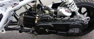
The official manufacturer of the 139QMB scooter engine is Hongling Corporation, which equips motorcycles not only of its own brand, but also of other brands with this engine.
The corporation sells power units to other manufacturers. The motor itself is very recognizable: the design features of the 139QMB engine and its markings on the left side of the crankcase immediately make it clear what kind of heart beats the scooter.
The motor has no flaws, does not require special treatment and calmly tolerates minor negligence and negligence. The manufacturer provides a guarantee for its products that covers the first 5 thousand kilometers. This mileage is enough for the new 139QMB 4t scooter engine to fully run in and grind in all elements and components of the systems.
The total service life of the engine is about 20 thousand kilometers, with the exception of 5 thousand running-in at an average driving speed of 90 km/h. The technical characteristics of the 139QMB engine are not bad: its power is enough for a two-seater full-size scooter.
Removing the variator
Remove the variator cover. There is nothing complicated about this: we unscrew all visible bolts and remove the cover from the engine. On the 157QMJ engine, in order not to bend the kickstarter return spring bracket, first remove the crank, remove the retaining ring from the kickstarter shaft, and only then remove the cover itself. You can, in principle, remove it this way, but then you will have to trim the bracket a little.
Removing a variator is not much easier than removing a generator. As with a generator, you need a good puller. Fortunately, you can make a puller yourself: for a 139QMB engine, instead of a puller, you can use a metal plate: remove the bendix from the niche, insert the plate into it, press the variator impeller tooth against the plate and unscrew the nut.
You can also make a more advanced puller: look for an unnecessary clutch disc from an IZH motorcycle, weld a rod and several hooks for the impeller teeth to it
For the 157QMJ engine, the puller is made according to a slightly different principle
You can go to the nearest tool store and buy a universal key for the grinder. It is very suitable for removing the variator of the 157QMJ engine and costs a penny
The principle of removing the variator is identical to the principle of removing the generator: fix the impeller with a puller, unscrew the nut, remove the variator from the axle. After removal, we completely disassemble the variator and check all its parts for wear.
On the 157QMJ engine there is a kickstarter gear behind the CVT. It is not so easy to remove, but if you are going to subsequently halve the engine, you will have to remove it.