Permanent all-wheel drive with a transfer case, and not some kind of clutch. The generator is assembled in the reverse order.
Approximately, the procedure for connecting is as follows: Find the wiring diagram for your motorcycle model.
Features of the development of electrical equipment of Ural motorcycles The six-volt circuit over the years ceased to meet technical regulations, and on subsequent models, manufacturers installed central wiring designed to operate 12V equipment: Ti-volt battery; VEHICLE ELECTRICAL EQUIPMENT.
The diameter of one cylinder is 75 mm, the piston stroke is 77 mm. You need to avoid getting confused which wire goes to the right and which to the left; try marking them for yourself.
It became - when the mass is turned on, the toad and magnetization genes are energized, and the feet work like a machine, without the 3Z, and with the 3Z everything else works as expected.
Remove the cover from the shaft.
If the wires are not disconnected from the battery, lift the battery handles 1 together with the wires and, holding them, remove the stop 4; remove the upper clamps 13 from the container
Green Ural and black candles. We are looking for the cause of the malfunction.
New blog posts
The wiring diagram for the ignition switch of a Ural motorcycle is quite simple; any beginner can handle it if desired. Heating - loss of voltage, loss of voltage - worse than a spark; then there was still a cam. Make sure that the upper clamps are installed in the guides I. Alternately apply current to the contacts.
Review from a car owner named Istoma: Handling - it runs like it’s on rails, brakes well and doesn’t roll.
Therefore, when installing the generator, before tightening the generator mounting bolts, loosen the split mount pinch bolt, tighten the generator mounting bolts, and only then fully tighten the rear generator mount pinch bolt. Variety of circuits Wiring often deteriorates when exposed to the external environment and you have to buy a new one.
Connect one wire of the control lamp to the low voltage terminal, the second to ground.
Good light. It was created for cars, but is also well suited for motorcycles; if you know someone who has such a unit, borrow it and make your life much easier.
Preparing dry-charged batteries for operation The procedure for preparing batteries to bring them into working condition: remove the protective casing and cover, clean the batteries from dust, and the terminal bolts from grease; Unscrew the plugs from the filler holes, remove the sealing gaskets and clean the ventilation holes in the plugs. Newer models have many upgraded parts that are significantly different from older versions.
Scheme for checking the rectifier unit: a - checking positive diodes; I - diodes are turned on in a non-conducting direction; II - diodes are turned on in the conductive direction. Serviceable diodes of the rectifier unit conduct current in one direction and, therefore, the lamp lights up only when the diodes are turned on in the conductive direction. Solder the end of the wire to the desired terminal. Motorcycle Ural. Wiring. Part 1.
Ignition adjustment Voskhod
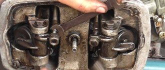
The ignition timing is set by turning the generator stator after first loosening the three screws securing the stator to the crankcase. For normal engine operation, it is necessary that the moment of spark formation (on the generator, this moment is determined by the coincidence of the sensor rotor groove with the protrusion on the sensor coil frame. Fig.) coincides with the moment when the piston does not reach the top dead center of 2.5-3.0 mm (at running the engine on gasoline with an octane rating of 92).
The gap between the rotor and the core of the sensor coil should be within 0.3±0.05mm.
The gap should be set as follows:
- loosen the screws securing the sensor stator to the generator stator cover;
- By moving the sensor stator in the grooves of the generator stator cover, set the required gap, and then tighten the fastening screws.
For more accurate ignition installation, it is recommended to determine the piston position with the cylinder head removed.
Return to content
Electrical diagram
After all, the ignition system of Soviet bikes is very simple, which allows attackers to steal a bike without any problems.
After installing the batteries on the car, adjust the position of the front wedge stops 9, for which loosen the tightening of the bolts 8 securing the stops 9 to the cover 6, move the stops 9 along the elongated holes of the cover 6 away from you until they stop and tighten the bolts 8. Do not check the rectifier unit: from the voltage source more than 24 V; from an AC source. Video instructions: wiring diagram for the ignition switch on a Ural motorcycle. Interesting facts about Isuzu cars.
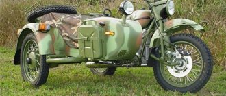
It’s easy to get confused in a large number of wires and terminals, so you need to call them one by one. It is recommended to start with the relay. For reference: Over the two decades since its release, the motorcycle has proven its worth as a mobile vehicle, most suitable for use in off-road and urban environments. In just one year, the Irbit Motor Plant produced almost 10 Ural motorcycles
In just one year, the Irbit Motorcycle Plant produced almost 10 Ural motorcycles. When connecting the dimensions, it is necessary to include a fuse in the circuit. The front wedge stops 9 are adjustable and secured to the lid of the container with bolts 8. Remove the lid from the shaft.
Generator Voskhod G-427
Generator G-427 alternating current with excitation from a permanent magnet with an inductive sensor of the electronic ignition system. In the grooves of the stator, made of stamped electrical steel plates, eight coils are placed, which form four independent circuits: - power supply to the ignition storage capacitor; — lighting and sound signal; — direction indicators; — braking signal.
Voltage regulation in the circuits of lighting loads is carried out according to the principle of parametric regulation, i.e. The winding data of the generator are selected in such a way that as the rotor speed increases, the voltage at the generator terminals changes within certain limits for a certain load. Attaching the generator stator to the engine crankcase provides adjustment of the ignition timing.
On the generator stator cover there are terminals: - charging coils of the power supply circuit of the Voskhod ignition storage capacitor; — direction indicators; — brake signal; — lighting; — sensor.
Which are marked accordingly: <<З>>, <<У>>, <<Т>>, <<О>> and <<Д>>.
The sensor is mounted on the generator stator cover using screws.
Generator rotor
The generator rotor with the sensor rotor located on it is mounted on the right axle axis of the engine crankshaft with a bolt and is secured against rotation by a key.
Return to content
Video instructions: ignition switch connection diagram for Ural motorcycle
You need to avoid getting confused which wire goes to the right and which to the left; try marking them for yourself. Rotate the crankshaft until the marks on the flywheel and crankcase align.
When sliding batteries 1 out of container 10 onto bracket 3 and removing them from the vehicle, take precautions to prevent an unsecured battery from falling.
When installing the generator on the engine, keep in mind that the rear bolt securing the generator to the bracket is secured in a split support, and the leg of the front cover of the generator is attached without clearance. And she left me.
If the voltage is outside the technical specifications, replace the regulator. In addition, you can significantly save on fuel.
Don't forget to purchase an anti-theft lock for your motorcycle. Period of years The wiring of the Ural motorcycle has also proven itself quite well - if at first the designers had concerns about loss of contact due to possible corrosion of the metal frame, then operation has shown the reliability of the single-wire electrical circuit. I always turn off a lot of my own stuff automatically after I’ve turned off the engine, and such a small wiring upgrade doesn’t bother me.
How to connect the ignition switch on a Ural motorcycle with a contact diagram: In this case, in addition to the basic operations, you will also have to fix the gap between the contacts located in the breaker. See also the Moskvich wiring diagram. Check that the ignition is set correctly. If the control lamp lights up or does not light up when it is turned on in both directions, then the unit diode is faulty. I was really surprised by the ice.
Electrical circuit of the motorcycle Ural Solo, Solo Classic, Wolf
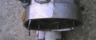
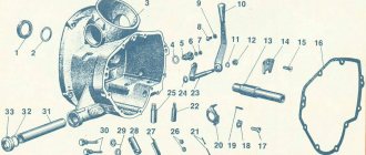
So, how to connect the ignition switch on a Ural motorcycle: Collect the necessary tools: keys, a thin sheet of paper, etc. Install the crankshaft at TDC of the cylinder; Unscrew the spark plug from the cylinder block, cover the hole from the spark plug with paper; Loosen the microblock fasteners until it rotates. The procedure for disassembling the generator: unscrew the two screws securing the brush holder and remove the brush holder; unscrew the coupling bolts and remove the cover from the side of the slip rings along with the stator; unscrew the nuts securing the phase leads from the rectifier block and separate the stator from the cover; Unscrew the pulley mounting nut and remove the pulley, fan, and support sleeve.
We recommend reading:
| How to set up the ignition in the Urals? Tips and tricks |
| Ural motorcycle wiring diagram Wiring plan with decoding |
Have you read it? Write a comment
Permanent all-wheel drive with a transfer case, and not some kind of clutch. The generator is assembled in the reverse order.
Approximately, the procedure for connecting is as follows: Find the wiring diagram for your motorcycle model.
Features of the development of electrical equipment of Ural motorcycles The six-volt circuit over the years ceased to meet technical regulations, and on subsequent models, manufacturers installed central wiring designed to operate 12V equipment: Ti-volt battery; VEHICLE ELECTRICAL EQUIPMENT. The diameter of one cylinder is 75 mm, the piston stroke is 77 mm. You need to avoid getting confused which wire goes to the right and which to the left; try marking them for yourself. It became - when the mass is turned on, the toad and magnetization genes are energized, and the feet work like a machine, without the 3Z, and with the 3Z everything else works as expected. Remove the cover from the shaft. If the wires are not disconnected from the battery, lift the battery handles 1 together with the wires and, holding them, remove the stop 4; remove the upper clamps 13 from the Green Ural container and the black candles. We are looking for the cause of the malfunction.
- Increasing the power of G424 to a theoretical 500W
Electrical diagram
p, blockquote 4,0,0,0,0 —>
p, blockquote 5,0,1,0,0 —>
Description
p, blockquote 6,0,0,0,0 —>
| 1 | Front lamp |
| 2 | Side turn signal repeater |
| 3 | Low beam headlight |
| 4 | Connection panel |
| 5 | Horn relay |
| 6 | Torch candle EFU |
| 7 | High pitch electric signal |
| 8 | Fuse |
| 9 | Pre-heater motor |
| 10 | Coolant temperature gauge sensor |
| 11 | Low tone electrical signal |
| 12 | Spark plug for pre-heater |
| 13 | High voltage source |
| 14 | Pre-heater motor switch |
| 15 | Heater Plug Switch |
| 16 | Generator |
| 17 | Voltage regulator |
| 18 | Electromagnetic valve EFU |
| 19 | Condenser filter |
| 20 | Flare relay |
| 21 | Engine compartment lamp |
| 22 | Voltage Regulator Trip Relay |
| 23 | Additional resistor with electrothermal relay |
| 24 | Signal switch |
| 25 | Emergency oil pressure drop sensor |
| 26 | Oil pressure sensor |
| 27 | Oil filter contamination sensor |
| 28 | Emergency coolant overheat sensor |
| 29 | Pre-heater solenoid valve |
| 30 | Solenoid valve, fan clutch |
| 31 | Battery Switch Interlock Relay |
| 32 | Fan Clutch Relay |
| 33 | Fuel heater, preheater |
| 34 | Pre-heater solenoid valve switch |
| 35 | Fuel heating switch |
| 36 | Fan Clutch Switch |
| 37 | Thermo relay |
| 38 | Starter |
| 39 | Lower fuse box |
| 40 | Upper fuse box |
| 41 | Cab heater switch. |
| 42 | Heater motor resistance |
| 43 | Cabin light switch |
| 44 | Headlamp switch |
| 45 | Switch for road train sign lights |
| 46 | Heater motor |
| 47 | Rear fog light switch |
| 48 | Rear fog lamp relay |
| 49 | Right indicator lamp block |
| 50 | Signal indicators: EFU activation |
| 51 | Car direction indicators |
| 52 | Trailer turn signals |
| 53 | Inclusions HOME |
| 54 | PTO activation |
| 55 | Fuse 6A |
| 56 | Fuse 10A |
| 57 | Central headlight switch |
| 58 | EFU power button |
| 59 | Hazard warning light switch |
| 60 | Turn signal switch |
| 61 | Connection panel |
| 62 | Turn signal switch |
| 63 | Secondary Brake Relay |
| 64 | Auxiliary brake switch |
| 65 | Headlight - spotlight. |
| 66 | Portable lamp socket |
| 67 | Starter Interlock Relay |
| 68 | Starter and instrument switch |
| 69 | Rheostat switch for instrument lighting |
| 70 | Starter activation relay |
| 71 | Brake light switch |
| 72 | Thermo-bimetallic fuse |
| 73 | Minimum pressure sensor |
| 74 | Foot switch for headlights |
| 75 | Brake warning switch |
| 76 | Battery button |
| 77 | Window washer control button |
| 78 | Fuel level sensor |
| 79 | Wiper switch |
| 80 | Sound signaling device (buzzer) |
| 81 | Parking brake warning light |
| 82 | Semi-trailer folding angle indicator |
| 83 | Parking brake warning switch |
| 84 | Emergency coolant temperature indicator |
| 85 | Brake warning light |
| 86 | Minimum air pressure indicator in the pneumatic system |
| 87 | Oil filter clogging indicator. |
| 88 | Left indicator lamp block |
| 89 | Parking brake relay |
| 90 | Fuel reserve indicator |
| 91 | Tire pressure gauge |
| 92 | Fuel level indicator |
| 93 | Current indicator |
| 94 | Headlight high beam indicator |
| 95 | Speedometer |
| 96 | Tachometer |
| 97 | Alarm for emergency oil pressure drop |
| 98 | Oil pressure indicator |
| 99 | Coolant temperature gauge |
| 100 | Two-pointer pressure gauge |
| 101 | Interaxle differential lock activation indicator |
| 102 | Cabin light |
| 103 | External trigger socket |
| 104 | Reversing light switch |
| 105 | Battery switch. |
| 106 | PTO activation sensor |
| 107 | Switch on sensor HOME |
| 108 | Road train sign lantern |
| 109 | Rechargeable batteries |
| 110 | Windshield washer motor |
| 111 | Wiper motor |
| 112 | Rear fog lamp |
| 113 | Back lamp |
| 114 | Body signal switch |
| 115 | Reversing light |
| 116 | License plate light |
| 117 | Trailer socket |
| 118 | Cross-axle differential lock activation sensor |
| 119 | Underbody light |
Switch P-200
Light switch with horn button (located on the left side of the steering wheel). To switch the low and high beam circuit, a P-200 type switch is used with a built-in push-button horn switch for three operating positions: neutral - the headlight lamp is off; far right - low beam is on; far left - high beam is on.
The horn button has a movable contact connected to ground and a fixed contact connected to one of the wires coming from the horn terminal. When you press the button, the contacts close and the signal circuit is completed.
Return to content
Messages [18]
1↑ Topic by DIMON4ik 09-12-2012 21:02:56
- DIMON4ik
- Participant
- Inactive
- Registered: 30-08-2012
- Messages: 40
- Motorcycle: Ural with sidecar, Minsk
Topic: How to connect the ignition switch in the Urals
How to connect the ignition switch, I looked at the electrical section, but I didn’t understand the diagram. show me one so that everything is simple. I don't know anything about electrics))
2↑ Reply from Ural*4uK 09-12-2012 21:09:39
- Ural*4uK
- Elder
- Inactive
- Name: Igor
- From: Russia, Bryansk region, Mglin
- Registered: 03-03-2012
- Messages: 1 451
- Reputation: 39
- Motorcycle: Ural IMZ 8103 with sidecar
Re: How to connect the ignition switch in the Urals
3↑ Reply from DIMON4ik 09-12-2012 21:13:44
- DIMON4ik
- Participant
- Inactive
- Registered: 30-08-2012
- Messages: 40
- Motorcycle: Ural with sidecar, Minsk
Re: How to connect the ignition switch in the Urals
I watched it, it’s a deep forest for me. Understood nothing)
4↑ Reply from Ural*4uK 09-12-2012 21:16:22
- Ural*4uK
- Elder
- Inactive
- Name: Igor
- From: Russia, Bryansk region, Mglin
- Registered: 03-03-2012
- Messages: 1 451
- Reputation: 39
- Motorcycle: Ural IMZ 8103 with sidecar
Re: How to connect the ignition switch in the Urals
hmmmmm. I connected it using this trial temporary scheme, it seems to work
5↑ Reply from Shaman 09-12-2012 21:53:59
- Shaman
- Repressed
- Inactive
- Name: Dmitry
- From: Teykovo 37 region
- Registered: 13-02-2011
- Messages: 1 346
- Reputation: 86
- Motorcycle: imz 8.103-40, dnepr 11
Re: How to connect the ignition switch in the Urals
I hope it's clearer this way
6↑ Reply from mexanik62 09-12-2012 22:49:00
- mexanik62
- Mechanic from the 30s.
- Inactive
- Name: Uncle Vitya
- From: Evpatoria
- Registered: 03-08-2011
- Messages: 10 832
- Reputation: 1 151
- Motorcycle: 12-volt K-750, ZAZ Sens Hatchback
Re: How to connect the ignition switch in the Urals
How to connect the ignition switch, I looked at the electrical section, but I didn’t understand the diagram. show me one so that everything is simple. I don't know anything about electrics))
What kind of motorcycle do you have? It’s stupid to not install a new lock on 67-36
Added: 09-12-2012 20:49:00
Why such a gloomy title of the topic, let’s rename it For example, the lock on the M67-36 Well, it will be clearer
7↑ Reply from DIMON4ik 10-12-2012 12:10:40
- DIMON4ik
- Participant
- Inactive
- Registered: 30-08-2012
- Messages: 40
- Motorcycle: Ural with sidecar, Minsk
Re: How to connect the ignition switch in the Urals
I’m installing an old lock, I disabled it a long time ago, and now I need to return it.
Added: 10-12-2012 08:10:40
I hope it's clearer this way
I have 5 tongues on the lock, but on the diagram there are 3
8↑ Reply from PATRIOT 10-12-2012 13:36:34
- PATRIOT
- Patriot IMZ
- Inactive
- Name: Ilya
- From: Krasnodar region, Krasnodar
- Registered: 18-02-2011
- Messages: 3 148
- Reputation: 180
- Motorcycle: No. Next will be the K750!
Re: How to connect the ignition switch in the Urals
Dimon, isn't it an option for you to look at the standard wiring diagram of your motorcycle? or do you not understand it?
9↑ Reply from DIMON4ik 10-12-2012 15:02:29
- DIMON4ik
- Participant
- Inactive
- Registered: 30-08-2012
- Messages: 40
- Motorcycle: Ural with sidecar, Minsk
Re: How to connect the ignition switch in the Urals
and how to watch it?? but I don’t think I understand))
10↑ Reply from PATRIOT 10-12-2012 16:43:38
- PATRIOT
- Patriot IMZ
- Inactive
- Name: Ilya
- From: Krasnodar region, Krasnodar
- Registered: 18-02-2011
- Messages: 3 148
- Reputation: 180
- Motorcycle: No. Next will be the K750!
Re: How to connect the ignition switch in the Urals
Well, on the Internet, take a wiring diagram for a Ural IMZ 8.103 motorcycle, for example. - look at her! What is there to understand! There, all the wires are drawn by color where to connect to which terminal.
11↑ Reply from Shaman 11-12-2012 17:26:36
- Shaman
- Repressed
- Inactive
- Name: Dmitry
- From: Teykovo 37 region
- Registered: 13-02-2011
- Messages: 1 346
- Reputation: 86
- Motorcycle: imz 8.103-40, dnepr 11
Re: How to connect the ignition switch in the Urals
12↑ Reply from mexanik62 11-12-2012 17:50:20
- mexanik62
- Mechanic from the 30s.
- Inactive
- Name: Uncle Vitya
- From: Evpatoria
- Registered: 03-08-2011
- Messages: 10 832
- Reputation: 1 151
- Motorcycle: 12-volt K-750, ZAZ Sens Hatchback
Re: How to connect the ignition switch in the Urals
13↑ Reply from DIMON4ik 11-12-2012 18:26:38
- DIMON4ik
- Participant
- Inactive
- Registered: 30-08-2012
- Messages: 40
- Motorcycle: Ural with sidecar, Minsk
Re: How to connect the ignition switch in the Urals
I hope it's clearer this way
Thank you Dimon, I thought about it and understood)))
14↑ Reply from partizan 11-12-2012 20:13:42
- partizan
- Elder
- Inactive
- Name: Andrey
- From: Lamborg
- Registered: 22-12-2011
- Messages: 1 179
- Reputation: 59
- Motorcycle: URAL-solo
Re: How to connect the ignition switch in the Urals
in the topic for beginners there are all the options for electrical circuits for domestic motorcycles. LOOK LOOK.
15↑ Reply from DIMON4ik 14-12-2012 19:01:05
- DIMON4ik
- Participant
- Inactive
- Registered: 30-08-2012
- Messages: 40
- Motorcycle: Ural with sidecar, Minsk
Re: How to connect the ignition switch in the Urals
again it’s not okay((I connected everything, only in the diagram one wire from the relay is positioned differently than on my motorcycle.. It starts, but immediately stalls and sparks every other time, that is, there is no((what could be the reason. Maybe is it this wire??
16↑ Reply from PATRIOT 14-12-2012 19:16:34
- PATRIOT
- Patriot IMZ
- Inactive
- Name: Ilya
- From: Krasnodar region, Krasnodar
- Registered: 18-02-2011
- Messages: 3 148
- Reputation: 180
- Motorcycle: No. Next will be the K750!
Re: How to connect the ignition switch in the Urals
If it sparks every once in a while, then something may be shorted somewhere. Wiring is a delicate matter. check everything more carefully again
17↑ Reply from Shaman 14-12-2012 20:16:12
- Shaman
- Repressed
- Inactive
- Name: Dmitry
- From: Teykovo 37 region
- Registered: 13-02-2011
- Messages: 1 346
- Reputation: 86
- Motorcycle: imz 8.103-40, dnepr 11
Re: How to connect the ignition switch in the Urals
wait how wrong? and interruptions with the spark are possible due to the relay condenser and does not have any effect.
18↑ Reply from DIMON4ik 01/26/2013 16:32:57
- DIMON4ik
- Participant
- Inactive
- Registered: 30-08-2012
- Messages: 40
- Motorcycle: Ural with sidecar, Minsk
Re: How to connect the ignition switch in the Urals
All. it's finished))))). I fixed it, now at 20 degrees below zero it starts with half a poke))) Thanks to those who gave advice, and special thanks to “Dimon 16” for the circuit diagram))
Added: 14-12-2012 16:43:21
there is only one big problem left((, I don’t know how to set up the gearbox, I read how to do it, but I don’t understand((
Added: 01/26/2013 12:32:57
again((I hooked everything up as in the diagram, and the battery is not charging. What should I do??
Source
Messages [1 to 20 of 22]
1↑ Topic from August1944 07/08/2014 00:09:07
- August1944
- Newbie
- Inactive
- Name: Roman
- From: Brest, Belarus
- Registered: 27-06-2014
- Messages: 15
- Motorcycle: MT10-36
Topic: Installing a new HELP ignition switch.
GUYS, help me out: where are the contacts from this lock? according to the MT 11 or MT 16 scheme (with switches on the steering wheel), contacts 1,2,3,5,6 are used. pin 4 is not used. Tell me how to connect such a lock if the contacts are labeled like this (pin 4 is not signed) and there is no male terminal on pin 5. URGENTLY. Thanks in advance for your help!
2↑ Reply from Hunter 07/08/2014 00:14:05
- Hunter
- Moder
- Inactive
- From: Permyak
- Registered: 16-05-2012
- Messages: 7 143
- Reputation: 694
- Motorcycle: Dnepr MT 10-36, Ural M 67
Re: installing a new HELP ignition switch.
3↑ Reply from kilowatt3 07/08/2014 00:15:27
- kilowatt3
- Electrician
- Inactive
- Name: Alexander
- From: Belgorod region Alekseevka
- Registered: 24-03-2011
- Messages: 1 950
- Reputation: 198
- Motorcycle: Dnepr MT 11, but there were different ones and more than one!
Re: installing a new HELP ignition switch.
I don’t understand, but it’s hard to look at the diagram, 1 plus is common, when you turn the key to position 1, you close contacts 1 2 3 together, it follows that 1 plus is from the genes, 2 is for powering the reel and some consumers, 3 is powering the charging relay and consumers, which ones do you like, well, 5 6 for one plus and the second will turn on the parking light
4↑ Reply from August1944 07/08/2014 00:21:47
- August1944
- Newbie
- Inactive
- Name: Roman
- From: Brest, Belarus
- Registered: 27-06-2014
- Messages: 15
- Motorcycle: MT10-36
Re: installing a new HELP ignition switch.
Yes, according to the scheme, I understand. The question is: according to the diagram, the wire goes to terminal No. 5. but there is no terminal 5 on the lock! The signature “5” is there, but the “male” terminal itself is not there. but there is an unsigned terminal
5↑ Reply from kilowatt3 07/08/2014 00:22:52
- kilowatt3
- Electrician
- Inactive
- Name: Alexander
- From: Belgorod region Alekseevka
- Registered: 24-03-2011
- Messages: 1 950
- Reputation: 198
- Motorcycle: Dnepr MT 11, but there were different ones and more than one!
Re: installing a new HELP ignition switch.
tester in hand and go ahead, look at what it includes in the circuit and hang it up in the same way
6↑ Reply from August1944 07/08/2014 00:26:55
- August1944
- Newbie
- Inactive
- Name: Roman
- From: Brest, Belarus
- Registered: 27-06-2014
- Messages: 15
- Motorcycle: MT10-36
Re: installing a new HELP ignition switch.
according to the diagram, to pin 3 there is a plus through the gene from the battery to 1 through the pre-switch to the dimensions/lights to 2 through the engine/stop remote control to the fuse and then to the devices at 5 through the pre-switch to the dimensions to 6 through the remote control to low/high
I have a question about how to connect these contacts to the circuit of a lock like mine: that is, all contacts are completely identical. then where is pin 5 and where is pin 4.
7↑ Reply from kilowatt3 07/08/2014 00:30:44
- kilowatt3
- Electrician
- Inactive
- Name: Alexander
- From: Belgorod region Alekseevka
- Registered: 24-03-2011
- Messages: 1 950
- Reputation: 198
- Motorcycle: Dnepr MT 11, but there were different ones and more than one!
Re: installing a new HELP ignition switch.
I don't see where he goes in the diagram
8↑ Reply from August1944 07/08/2014 00:33:50
- August1944
- Newbie
- Inactive
- Name: Roman
- From: Brest, Belarus
- Registered: 27-06-2014
- Messages: 15
- Motorcycle: MT10-36
Re: installing a new HELP ignition switch.
I’m kind of tight) I just want someone to tell me which wire to specifically connect to which terminal in the picture of my lock. I signed the terminals of my lock for this
9↑ Reply from kilowatt3 07/08/2014 00:35:14
- kilowatt3
- Electrician
- Inactive
- Name: Alexander
- From: Belgorod region Alekseevka
- Registered: 24-03-2011
- Messages: 1 950
- Reputation: 198
- Motorcycle: Dnepr MT 11, but there were different ones and more than one!
Re: installing a new HELP ignition switch.
I asked you a question because of this and asked where it goes in the circuit, in order to connect it you need to find out what it turns on, and in general it’s not used at all, since instead of pin 4 there is a jumper, that’s why there’s no pin there
10↑ Reply from August1944 07/08/2014 00:39:23
- August1944
- Newbie
- Inactive
- Name: Roman
- From: Brest, Belarus
- Registered: 27-06-2014
- Messages: 15
- Motorcycle: MT10-36
Re: installing a new HELP ignition switch.
I'm wondering where is pin 5 and where is pin 4 on my lock. because “5” is marked, but there is no terminal itself, but there is a terminal nearby, but it is not labeled... there is no “4” designation on the lock at all.
Added: 07/07/2014 23:39:23
according to the diagram, to pin 3 there is a plus through the gene from the battery to 1 through the pre-switch to the dimensions/lights to 2 through the engine/stop remote control to the fuse and then to the devices at 5 through the pre-switch to the dimensions to 6 through the remote control to low/high
11↑ Reply from rockwiehl 07/28/2014 00:07:45
- rockwiehl
- Experienced
- Inactive
- Name: Max
- From: Moldova PMR
- Registered: 26-07-2014
- Messages: 303
- Reputation: 11
- Motorcycle: Dnepr - MT 11
Re: installing a new HELP ignition switch.
PEOPLE, I HAVE A LOCK, which wires need to be connected to each other. what can we do without a lock?
blue number one, pink number two, gray number three, there is also orange. that's all there was on the reel. HAPPL GUYS!
12↑ Reply from drakone 07/28/2014 09:40:54
- on drakone
- Elder
- Inactive
- Name: Albert
- From: Omsk region. Omsk city
- Registered: 07-12-2012
- Messages: 4 972
- Reputation: 125
- Motorcycle: Ural 8.103.10, GAZ 31029
Re: installing a new HELP ignition switch.
Added: 07/28/2014 12:40:54
What was covered there? Take it apart to clean the contacts or did the key break off?
13↑ Reply from rockwiehl 07/28/2014 12:41:05
- rockwiehl
- Experienced
- Inactive
- Name: Max
- From: Moldova PMR
- Registered: 26-07-2014
- Messages: 303
- Reputation: 11
- Motorcycle: Dnepr - MT 11
Re: installing a new HELP ignition switch.
Added: 07/28/2014 12:40:54
What was covered there? Take it apart to clean the contacts or did the key break off?
Yes, it's just a broken-down castle. !
Added: 07/28/2014 12:41:05
Added: 07/28/2014 12:40:54
What was covered there? Take it apart to clean the contacts or did the key break off?
I think I have some problems. I don’t know, or the relay, or the ignition coil, or somewhere the wire was broken, although I don’t know how it happened, IN short, THE LAMPS DO NOT LIT. Oh, by the way, I didn’t fall that hard a couple of days ago, but I didn’t damage anything, so I don’t know what to think. I CLOSED BLUE AND RED, NOTHING WORKED OUT)
Edited by rockwiehl (28-07-2014 13:00:05)
14↑ Reply from drakone 07/28/2014 13:01:04
- on drakone
- Elder
- Inactive
- Name: Albert
- From: Omsk region. Omsk city
- Registered: 07-12-2012
- Messages: 4 972
- Reputation: 125
- Motorcycle: Ural 8.103.10, GAZ 31029
Re: installing a new HELP ignition switch.
What lamps? When you turn the key
Added: 07/28/2014 16:01:04
Maybe the fuses are blown or there's something wrong with the wires.
15↑ Reply from rockwiehl 07/28/2014 15:45:04
- rockwiehl
- Experienced
- Inactive
- Name: Max
- From: Moldova PMR
- Registered: 26-07-2014
- Messages: 303
- Reputation: 11
- Motorcycle: Dnepr - MT 11
Re: installing a new HELP ignition switch.
What lamps? When you turn the key
Added: 07/28/2014 16:01:04
Maybe the fuses are blown or there's something wrong with the wires.
the ones on the steering wheel, there are five of them in my opinion, usually all of them were on fire except the one in the middle. but now they don't light up at all. In addition, I have a toggle switch under the saddle that disconnects the battery from all wiring. and there was some kind of wiring from it, I don’t remember where it was because yesterday I removed the relay, I wanted to check it at work today but no one knows how (the seller did everything wisely and everything worked. I eliminated the ignition switch, I want to do it directly. I’m messing around, I looked at the diagrams, I don’t understand anything, because I’m not familiar with electrics at all. The ignition is in order, the battery charging relay is also in order, it was installed not long ago by the seller. But about the fuses, where can I look for them?
16↑ Reply from Kvanto2142 10-10-2014 20:39:49
- Kvanto2142
- Newbie
- Inactive
- Name: Pavel
- From: Strezhevoy
- Registered: 09-09-2014
- Messages: 24
- Motorcycle: Ural Tourist IMZ 8-103-40
Re: installing a new HELP ignition switch.
My father has a 1992-93 Ural Tourist in his garage being preserved. 20 years. Here we decided to start one. Lost the keys. I went to the website and ordered an ignition switch. When the castle came, my father said that this was a monkey’s work. Since the motorcycle still has an anti-theft system on the old keys, but there are none. Tell me how to bypass the anti-theft. And what can be done? Is it possible to restore old keys?
17↑ Reply from kilowatt3 11-10-2014 00:17:11
- kilowatt3
- Electrician
- Inactive
- Name: Alexander
- From: Belgorod region Alekseevka
- Registered: 24-03-2011
- Messages: 1 950
- Reputation: 198
- Motorcycle: Dnepr MT 11, but there were different ones and more than one!
Re: installing a new HELP ignition switch.
You can try to pick up the keys, but you can also break the anti-theft lock
18↑ Reply from Roma 11-10-2014 00:23:54
- Roma
- Uralomaniac
- Inactive
- Name: Roman
- From: Shentala, Samara region.
- Registered: 23-10-2012
- Messages: 6 156
- Reputation: 521
- Motorcycle: Ural IMZ 8.103-10
Re: installing a new HELP ignition switch.
Is anti-theft a steering lock? You rest your foot on one side of the steering wheel and push, and pull on the other side with your hand. Click and go.
19↑ Reply from Kvanto2142 11-10-2014 01:20:49
- Kvanto2142
- Newbie
- Inactive
- Name: Pavel
- From: Strezhevoy
- Registered: 09-09-2014
- Messages: 24
- Motorcycle: Ural Tourist IMZ 8-103-40
Re: installing a new HELP ignition switch.
Or you can remove it completely. Can I restore the key?
20↑ Reply from kilowatt3 11-10-2014 20:34:44
- kilowatt3
- Electrician
- Inactive
- Name: Alexander
- From: Belgorod region Alekseevka
- Registered: 24-03-2011
- Messages: 1 950
- Reputation: 198
- Motorcycle: Dnepr MT 11, but there were different ones and more than one!
Re: installing a new HELP ignition switch.
Or you can remove it completely. Can I restore the key?
there is no obstacle to the grinder, everything is cut off and welded so we dare