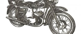
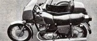
First, you need to understand the features of the motorcycle. IZH Jupiter-5 is a vehicle designed for road travel with different surfaces. You can attach a stroller and a cargo module. The appearance of Jupiter-5 is distinguished by the strict classics inherent in the Soviet era, but at the same time it has its own individuality.
The demand for this model lies in the small dimensions of the motorcycle, as well as decent power for that time. The engine of this motorcycle has two cylinders and two strokes. The cylinders are arranged in-line. The maximum developed power reaches 25 horses, which is 3 more than the single-cylinder IL Planet-5. This engine allows the motorcycle to move at a maximum speed of 120 km/h, while it has low fuel consumption.
What sets the bike apart is its ability to operate even in harsh climatic conditions. It is not at all whimsical: it can start both in -30 degrees and in heat over +40, and is not afraid of rain and dirt. However, moving on the ground during rain is not as easy as we would like. Unlike the “Planet”, during the trip you don’t feel any unnecessary vibration , the movement is dynamic and very smooth.
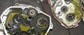
The Izhevsk Machine-Building Plant began producing IZH Jupiter-5 in 1985, so spare parts are always available. However, the quality leaves much to be desired, which is why parts wear out quickly and the motorcycle requires fairly regular repairs. Sometimes, to find the cause of a breakdown, you have to disassemble half of what you didn’t even know about. Fortunately, in IZh everything is quite simple and the repair can be done at home. Repairing the IZ Jupiter 5 engine is not a difficult task, but if you are going to ride this motorcycle often, then you should not neglect to do the work correctly.
The main problems of Jupiter-5 include the current shock absorbers and cylinders, which alternately refuse to operate the engine. If you have encountered similar problems, then this article may help you in solving one of the annoying problems.
Assembly
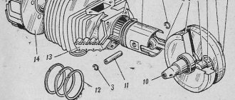
In a carefully washed and prepared for assembly crankcase we place the input shaft, the first gear gear and the follower shaft with pre-selected shims.
We put a fork on the gear-carriage for engaging the second-fourth gear (it is smaller than the gear-carriage for engaging the third-first gear, you can’t go wrong) as shown in the picture. We put the gear on the input shaft and insert the fork pin into the upper groove of the follower shaft.
We put a fork on the gear-carriage for engaging the first-third gear, as shown in the picture, place it on the first gear gear and insert the fork pin into the lower groove of the copy shaft.
We install the fork guides in their places (with grooves towards the clutch basket). By the way, if necessary, the “Planetovskaya” gearbox can be assembled and disassembled without disassembling the clutch basket and without removing the guides. But to do this, during installation you will have to pull the tracing shaft towards you a little, insert the pins of the forks into the grooves and after that, remove the locking bar and push the tracing shaft all the way.
Install the intermediate shaft.
On older engines, the end gear is installed separately. On later ones, it is made integral with the intermediate shaft.
We fill the return spring of the gear shift shaft as shown in the picture.
We check the functionality of the gearshift shaft pawls: compress and unclench them several times
We pay special attention to their working edges: they should be sharp and not licked. And don’t forget to check the spring that compresses the pawls: it must be of the correct shape and ensure the elasticity of the pawls’ movement
We squeeze the pawls and install the gear shift shaft in its place.
We rotate the tracking shaft with the mark on the body towards the gear shift shaft and so as not to miss the mark during installation, we cover the gap between the teeth opposite the mark of the tracking shaft with lithol or paint it. It will be more noticeable this way.
We look for a mark on the sector and when putting the sector on the gear shift shaft, we combine the mark on the sector with the mark on the tracking shaft body: the tooth opposite the sector marks should strictly fit between the teeth opposite the mark of the tracking shaft.
To ensure that our marks do not get lost during installation, we tie together the sector and the copy shaft with ordinary sewing thread.
We put standard thrust washers on the input and follower shafts and insert the guide bushings of the gearbox cover into place.
We degrease the surfaces, apply sealant, lay the gasket, install the cover and tighten the mounting bolts with the maximum possible force. We adjust special washers under the bolts marked with yellow arrows.
After tightening the gearbox cover, we check the axial play of the primary and secondary shafts. Normal: 0.2-0.4mm.
If the play is greater than normal, remove the plate, seat the bearing and adjust the required number of shims under it.
"Sores"
There are three problems in the planetary checkpoint:
- Oil leak from the intermediate shaft plug
- Poor gear engagement in first gear
- Constantly loosening the bolts securing the gearshift shaft stop
I solve the problem with oil leakage very easily and simply: I take out the retaining ring; I remove the intermediate shaft bearing, degrease the plug, retaining ring, mounting hole, then apply sealant to the outer edge of the plug, put it in place and immediately press it with the bearing and voila - the leak is eliminated!
Due to a factory defect, the gear-carriage for engaging the first-third gear does not fully engage the first-gear gear with its cams, but only in a small part, barely catching the gear with its cams, which is why the edges quickly wear out and the first gear begins to knock out.
This moment is clearly visible in the photo. For this particular gear, the hook was no more than a couple of millimeters. It is difficult to cure this “sore”: from the side of the first gear gear, you need to grind the end of the intermediate shaft by 3-4 mm and, using adjusting washers, move the first gear gear to the carriage. I don't see any other way.
During operation, the bolts securing the stop are constantly unscrewed, either due to vibration or something else - they are unscrewed and that’s it, no matter how you tighten them... Even special lock washers do not help. I struggled with this disgrace for a long time using all the traditional methods known to me and came to the conclusion that the best solution to this problem is red thread locker. Feel free to put bolts on it and get rid of this problem once and for all.
Repair
Once the unit has been gutted, you can begin to determine the parts that need to be replaced. As a rule, you have to buy a set of shims, a set of gaskets and sealant. This is the case if there are no more serious damage. Once you have decided on the elements to be replaced, you will need to adjust the worm shaft axis, and after final assembly, the clearance along the axis of the primary, intermediate and secondary shafts.
Adjusting washers are placed on the far ledge of the copy roller; they should be lubricated with a special compound. A support washer is mounted on the near edge, and the shaft is put in place. It should be turned so that the neutral sensor with its protrusion fits into the deepest groove. Then, using a ruler (without the gearbox cover yet) on the plane of the crankcase, measure the gap between the washer and the dipstick. It should be no more than 0.2 mm. Depending on the indicator, regulators are added or removed. If it is impossible to accurately set the gap, it is better to make it smaller.
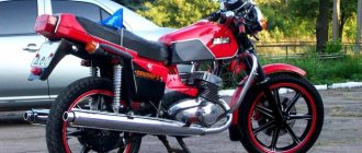
How did the motorcycle turn out the way it is?
The metal is sanded and coated with clear acrylic varnish. Selected color combinations and everything glossy are still boring from fiddling with computer programs. I wanted something like the so-called post-apocalyptic industrial theme. Here, for example, from the Detroit Bros workshop:
In general, I decided to assemble the Jupiter without the side borders and so that it would all shine with the steel from which it is made.
I bought a kilogram package of car varnish, it turned out to be acrylic, from Vika (about 500 rubles). I also bought thinner for acrylic paints and varnishes, also from Vika (a couple of jars for 90 rubles each), but later the hardener ran out faster than the thinner (a small jar of hardener was included with a jar of varnish). It seems that the domestic solvent R-12 is friendly with any acrylic paints and varnishes, but I have not checked.
I planned to paint with a purchased touch-up airbrush from MATRIX - with a simple round nozzle, a 0.2-liter aluminum tank, designed specifically for regular paint (not for all sorts of filling primers, which require a large diameter nozzle, greater pressure and, accordingly, greater air flow), produces spot from 5 mm to 4-5 centimeters, economically consumes paint.
I bought this touch-up airbrush for 690 rubles. And for 200 rubles a filter drier is small for him, for another 50 rubles for a set of two flanges (for a thin oxygen hose) and two nuts for a bayonet connection of such a flange to the airbrush.
On occasion, I got the compressor quite inexpensively, homemade, from a compressor from a refrigerator, a small receiver, a pressure gauge on the receiver itself, and an oxygen reducer with a thin oxygen hose. I've already modified it a little:
And also modified:
Such a compressor will not handle spray guns with high air consumption, but my touch-up airbrush works, and a small airbrush will work even more so. Although you can try a small spray gun with an LVLP spray system (originally made to work at low pressure and air flow) from IWATA, for example (I saw it on the Internet for 2300 rubles). But the compressor works no louder than a refrigerator. Otherwise, I would buy a compressor from my next salary (this is approximately 5,000 - 7,000 rubles).
Common faults
The most common problem with IZ Planet 5 is the spontaneous switching off of second gear. This problem is common on many other motorcycles, but this breakdown is often associated with careless gear shifting. When the first gear “spins” to high speeds, bypassing the “neutral” gear, the engagement with the second speed gear causes an impact, which causes wear. To prevent such a malfunction, it is not recommended to spin the first gear too much. But if the second one still dies, then some ways to eliminate the problem are possible:
The simplest method that will help in some cases. Place the motorcycle on its right side, then remove the kick starter and gear shift lever along with the shaft. Then remove the left crankcase cover, and then remove the clutch basket along with the discs. During operation, the gearbox gears wear out, which causes the meshing of the teeth to deteriorate. This leads to slipping and jerking of the transmission until the second gear fails. Sometimes, when replacing a gear, the problem is not always solved, and lies in the wear of the bearings of the input shaft, which moves to the left over time due to vibrations. To fix the problem, you need to remove the stopper of the input shaft bearing, then move this bearing with light blows of a mallet or with a hammer through the “spacer”, so as to move the shaft to the right. To fix it in this position, you should place washers of appropriate diameter under the bearing. Using the number and thickness of washers, ensure that there is no play in the input shaft, then return the bearing stopper to its place, reassemble the clutch basket and other parts in the reverse order.
- If fourth gear disappears. This is often due to failure of the secondary shaft bearings. This is due to the appearance of axial play in the secondary shaft when the bearings are displaced or fail. This malfunction can be repaired in the same way as repairing the second gear by removing the left crankcase cover.
- If the gear shift jams from upshift to downshift, the spring of the shift mechanism pawls has broken and must be replaced.
- If the gearbox switches tightly after assembly, it indicates incorrect installation of the adjusting washers.
Tuning the IZH Jupiter engine
Before you start, you need to decide how much power you would like to give to your engine. If you are quite satisfied with the average power, then you will need a ZiD-200 resonator. But if you want to make the IZH Jupiter 5 motorcycle fast and powerful, start tuning the engine by installing a resistor from the SMB-5 “motoblock”.
Replacing the air filter plays a big role in engine modification. The better the air is cleaned, the more horses the engine will be able to produce. After all, the degree of engine overheating depends on the amount of incoming air. It is best to use imported air filters. They provide improved cleaning and longer service life.
Next you should work hard on the injection system. An excellent option is to install a “Planet” carburetor with a diffuser diameter of 0.32 cm. Two carburetors will provide much greater acceleration and good dynamics. We take the flanges securing the cylinder from the standard tube, grind out the aluminum studs, and cut off the flange from the carburetor from the inlet tube from the Planet.
We grind the ends of the cylinder heads on a machine, and press the cylinders themselves. The maximum permissible volume of PIC is 18 cubic meters. see Install factory copper layers under the cylinder heads. And we adjust the ignition advance angle to increase compression.
We use the second flange from the old carburetor. Then we weld the parts using “cold” welding. And finally, we modify the assembly to be compatible with the inlet channels. all the cracks with epoxy liquid . Voskhod carburetors will provide uniform traction. In this simple way, you can add not only a couple of additional horses to your pet, but also provide more lively dynamics that give a good riding experience. The motorcycle is very reliable for everyday use, and if you take good care of it, breakdowns will occur very rarely.
Detection of faulty parts
To learn how to determine the damage and degree of wear of gearbox gears, consider the classification by which you can make the right decision about repairs. The gear needs to be replaced if:
- there is at least one broken tooth, or the presence of cracks in any part of the tooth caused by plastic deformation of the gear material.
- when the working surface of the gear is chipped by 20 percent or more, when the depth of chipping is 5 percent or more of the tooth thickness.
- if there is corrosion on the working surface of the gears;
- if the contact patch is less than 80 percent of the width of the teeth, and less than 60 percent of the height.
Main problems and their solutions
Disassembling the IZ Jupiter 5 engine, the video of which is presented below, is carried out not only as problems arise, but also for preventive purposes. For example, cleaning the carburetor is one of the conditions for maintaining stable engine operation.
The IZ Jupiter 5 engine diagram is simple even for inexperienced motorists. Therefore, during repairs there will be no difficult issues. In most cases, breakdowns occur due to the negligence of owners who improperly operate the moped and do not perform regular maintenance. For example, incorrect selection of oil for a particular time of year. So, if any part wears out, it must be replaced.
Important
When performing these operations, follow the mark in the middle part of the sector. It should coincide with a similar mark on the shaft. The last step is to install the crankcase cover. If the work is carried out correctly, it will sit in its place without problems.
It is necessary to ensure that all rods and shafts coincide with their original mounting sockets. They should rotate freely without creaking or jamming. Use moderate force when tightening the screws as the threads in a soft metal crankcase can easily be stripped. All fasteners are tightened evenly to avoid distortion.
Final stage
Next, the second and third speed gears are removed from the input shaft, after which the input shaft is dismantled. To do this, you will need to carefully knock it out using a stopper and a light hammer. The upper and lower forks are removed.
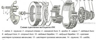
Next comes the intermediate shaft assembly. Using a screwdriver or other suitable tool, bend the clamp with the neutral indicator and carefully pull out the worm wheel. On its far side there are shims that could stick to the crankcase. They need to be collected and stored with the rest of the removed parts. Next is the turn of the copy shaft. Check the edges of the shaped sockets in which the guide forks move. They should not have chips or dents. We unscrew a couple of screws securing the switching mechanism, which is also removed. Now you can replace unusable parts and assemble the Izh-Planet 5 gearbox according to the scheme. The figure below shows: retaining cap (1), bolt (2), crankshaft sprocket (3), double-row chain (4), clutch drum (5), input shaft (6).
Tools
Tools you will need:
- Drill or screwdriver
- Metal drill 4 - 5 mm
- Flat file
- Technical hair dryer
- Mandrels. Plumbing fittings can be used as mandrels
- Powerful flat head screwdriver
- Open-end or socket wrench 14
- Clamp
- Hammer or mallet
- Oil can or syringe
- Sealant