Technical characteristics of the scooter TULA T-200
Total information
Type – Heavy road single; Base, mm - 1380; Ground clearance, mm - 120; Overall dimensions, mm: Length – 1930; Width – 515; Height - 1100; Fuel tank capacity – 12.5 – 13.35 liters; Weight, kg: Dry – 160; Operational – 175; Fuel consumption rate on the highway, l/100km – 3.5; Fuel range on the highway, km – 360; Maximum speed, km/h; - 80; Main capacities, l: Gearbox housing – 1.0; Front fork vibration damper – 0.25; Rear suspension – 0.18;
Engine
Type – Single-cylinder two-stroke with return two-channel purging and forced air cooling; Cylinder diameter, mm – 62; Piston stroke, mm – 66; Working volume, cm cubed – 197; Maximum power l. With. - 8; Compression ratio – 6.6; Number of piston sealing rings – 3; Material: cylinder head – aluminum alloy; head gaskets – reinforced asbestos; pistons – aluminum alloy; Piston pin diameter, mm – 15; Valve distribution phases: opening of the intake window - 67.5 degrees b.c.t. closing – 67.5 degrees after t.m.t. opening of the outlet window - 66 degrees BC. closing - 66 degrees after BC. opening of purge windows - 54 degrees BC. closing - 54 degrees after ground mt.
Supply system
Carburetor - one K-28-G; Diffuser diameter, mm – 24; The fuel filter is a mesh filter in the sump.
Transmission
Forward gear – chain; bushing chain operating in an oil bath, 2.35. Chain size, mm – 9.525 by 9.5; Clutch - multi-plate operating in an oil bath; Number of disks: leading – 5; slaves – 5; Number of springs – 5; Gearbox – four-speed; Speed change control – foot control with electric speed change indicator; Gear ratio: at first speed – 3.0; – second – 1.643; — third – 1.233; — fourth – 0.90; Overall gear ratio: At first speed – 15.8; - second - 8.65; — third – 6.5; - fourth - 4.7
Ignition and electrical equipment
Ignition type – battery dynamo; Ignition coil – B-51; Breaker – mounted on the generator stator; Rechargeable battery – 3-SMT-11; Generator – dynastarter DS-1; Voltage, V – 12; Power, W - 90; Glow plug – A11U; Relay-regulator – PP – 45; Signal – S-36; Headlight – FG-50B; Ignition timing is 5.5 degrees plus or minus one degree before T.M.T. Ignition timing adjustment – Automatic, with a centrifugal regulator; Gaps, mm: Between breaker contacts – 0.4 – 0.6; — spark plug electrodes – 0.6 – 0.7;
Chassis
Frame – tubular welded; The front and rear wheel suspension is of the lever type with springs and a hydraulic vibration damper; Brakes - shoe; Wheels – disc collapsible interchangeable (on discs); Tire size, in inches – 4.00 – 10; Air pressure in tires (first number without a passenger), atm: Front wheel – 1 atm, 1.5 atm; Rear wheel – 1.5 atm, 2.0 atm.
Return to contents — ↑
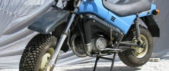
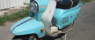
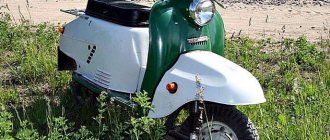
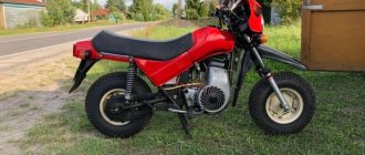
Motor scooter Tula T-200
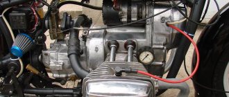
The T-200 scooter is equipped with a single-cylinder two-stroke engine with crank-chamber purging and forced air cooling with a power of 8 liters. With.
The main part is a block-type crankcase, which houses the crank mechanism, gearbox, clutch, motor chain and dynastarter.
Cylinder 2 is cast from fine-grained cast iron, on the outer surface of which cooling fins are located. The cylinder has an inlet, two bypass and exhaust channels.
The inlet channel has a pipe for connecting the K-28G carburetor.
The exhaust channel is connected to an exhaust pipe ending in a muffler.
Cylinder head 1 is cast from aluminum alloy and has fins for heat dissipation. A copper-asbestos gasket is installed between the head and the cylinder.
Piston 3 is aluminum. It has a convex bottom and is connected to a stamped steel connecting rod using piston pin 5. Three sealing rings 4 are installed on the piston.
A bronze bushing is pressed into the upper head of the connecting rod, and a double-row roller bearing is pressed into the lower head. The piston pin is lubricated through six holes drilled in the upper end of the connecting rod.
Crankshaft 7 is not dismountable, composite, consists of two journals pressed onto the crank pin. The shaft rotates on two ball 9 and one roller bearings.
The crankcase is cast from aluminum alloy. Consists of 16 right and 8 left halves. It is closed with lid 14.
The crankcase halves are connected using screws screwed into the left half.
Cooling is carried out by the air flow created by the fan impeller 20.
Lubrication of the rubbing surfaces of the T-200 motor scooter is carried out similarly to the lubrication of the VP-150 motor scooter.
The power system consists of a fuel tank, an air cleaner, a K-28G carburetor, a suction pipeline and fuel lines with a tap.
Carburetor K-28G - with a horizontal throttle valve and air-mechanical fuel braking, consists of two main parts: a float chamber 10 and a horizontally located mixing chamber 2.
Fuel enters the float chamber from the fuel tank through a fitting and a shut-off needle, the conical part of which fits into the socket of the cover 8. A hollow float is fixed to the needle using a pin spring. On the cover of the float chamber there is a float stopper 7.
From the float chamber, gasoline flows through the main jet 22 into the mixing chamber. Where are the throttle valve 24 with the corrector 19 located. And the carburetor idle system.
In the closed position, the spool and the corrector are held by springs 26 and 18. The idle system includes a screw 5 for adjusting the quality of the mixture and a screw 13 for adjusting the amount of the mixture.
The K-28G carburetor has two operational adjustments: for idling and at medium speed.
On the T-200 scooter engine, the air entering the carburetor is cleaned using a contact-oil air cleaner.
With its pipe 3, the air cleaner is mounted on the inlet pipe of the carburetor.
Return to contents — ↑
Adjusting the ignition timing
We install the piston at the top dead center (TDC), insert the bore gauge of a caliper into the spark plug hole, extend the bore gauge until it rests on the bottom of the piston, remove the caliper from the hole and extend the bore gauge to the plus side by 3.5-4 mm and fix the resulting value with a locking screw.
Turn the engine a little clockwise, insert a caliper into the spark plug hole, turn the engine counterclockwise until the piston touches the bore gauge.
If you have an indicator, then the matter becomes much simpler: fix the indicator in the spark plug hole, reset the scale to zero, turn the fan clockwise until the indicator pointer reads 3.5-4 mm.
We insert tissue paper between the contacts of the breaker, unscrew the adjusting bolts, move the contacts along the grooves in a clockwise direction (to the right), as soon as the paper falls out, we fix the contacts with the bolts.
You can also adjust the advance using a control light: we connect one wire of the light bulb to ground, the second to the wire going to the contact, just like in the case of paper, we manipulate the contacts and as soon as the light comes on, the desired position of the contacts is found.
Using a light bulb to adjust the timing is both more convenient and simpler, but not everyone has the original ignition, and many have a magneto, so it’s not always possible to use a light bulb.
Electrical equipment of the Tula T-200 scooter
The T-200 scooter is equipped with two 3-SMT-P batteries with a capacity of 11 Ah each. The batteries are connected in series, which made it possible to obtain a total voltage of 12 V. The series connection ensures that the engine starts using a dynastarter.
The DS-1 dynastarter is a direct current electric machine, which, when starting the T-200 scooter, works as an electric motor, and during driving it generates electricity to power lighting devices, ignition system devices and to recharge batteries.
When starting the engine, the dynastarter consumes a current of about 120 A, and when operating in generator mode, its power is 90 W.
Armature 1 of the dynastarter is mounted on the crankshaft and is locked using a key. Stator 3 is attached to the engine crankcase, has six poles formed by a series winding, and six poles formed by a shunt winding.
When starting the T-200 scooter, the poles of the series winding are turned on and active, and when the dynastarter operates as a generator, the poles of the shunt winding are activated.
The dynastarter works in conjunction with the relay-regulator PP-45, which provides: - turning on the dynastarter when operating as a starter; — automatic switching on and off of the dynastarter operating in generator mode from the power supply network of current consumers; - maintaining, regardless of the engine crankshaft speed, the current voltage generated by the dynastarter within certain limits.
The PP-45 relay-regulator consists of a housing in which the starting and reverse current relays and a voltage regulator are mounted.
All relay-regulator devices are closed on top with a lid.
The starting relay is switched on using the ignition key into the current circuit supplied from the battery to the stator poles formed by the series winding, and the dynastarter begins to work as a starter.
To turn off the start relay, just stop pressing the ignition key. The reverse current relay and voltage regulator are similar in their purpose, design and operation to similar devices of other types of relay regulators described above.
The B-51 ignition coil, installed on the T-200 scooter, is used to convert low voltage current (12 V) into high voltage current (14-16 thousand V).
The breaker is connected to the circuit of the primary winding of the ignition coil and ensures the induction of high voltage current in the secondary winding at the right moments.
The opening of the contacts of the breaker 10 and 11 occurs at those moments when the textolite pad 6 of the lever 9 leaves the protrusion of the cam 8, rotating on an axis fixed to the hub of the dynastarter armature.
Fixed contact 11 is located on stand 3, pressed to the base 1 of the breaker with a screw. Movable contact 10 is soldered to the end of lever 9 and connected by wire to the primary winding of the ignition coil.
For normal engine operation, the gap between the breaker contacts must be within 0.25 - 0.35 mm.
The opening of the contacts should begin at the moment when the engine piston is 3 - 4 mm before the c. m.t.
The gap between the contacts is adjusted by rotating the adjusting screw 2.
The T-200 scooter engine has an automatic ignition timing device, fixed with its base 1 to the dynastarter armature and rotates with it.
The weights 6 with their protrusions fit into the grooves of the cam 3 of the breaker. Each weight sits on a separate axis and is pulled by a spring 5 to the cam.
When the engine begins to develop speed, the weights, under the influence of centrifugal force, begin to overcome the force of the springs and move apart. In this case, the short arms of the weights turn the cam against the direction of its rotation, and the opening of the breaker contacts begins earlier.
This provides the necessary time for more complete combustion of the working mixture in the engine cylinders, which is especially necessary at high crankshaft speeds.
When the engine reaches 2500 - 3000 rpm. The weights disperse to their stops, and the machine no longer changes the achieved ignition timing.
The T-200 scooter uses A11U spark plugs with a gap between the electrodes of 0.6 - 0.7 mm.
The FG-50B headlight, installed on a T-200 scooter, consists of an optical element, a diffuser, adjustment and fastening parts. A two-filament lamp with low and high beam filaments is installed in the central socket.
The rear light serves to illuminate the license plate in the dark and to signal the braking of the scooter.
The S-30 sound signal installed on the T-200 scooter is similar in its effect to the S-34 signal on the VP-150 scooter.
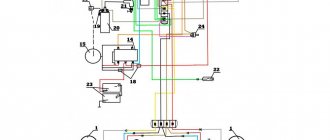
Electrical diagram of the Tula T-200 scooter
The T-200 scooter has a light indicator of the selected speeds.
When any speed is turned on, the electric switch interlocked with the gear shift mechanism closes the current circuit from one of the indicator lamps.
If the gearbox is in neutral, the green warning light located on the instrument panel lights up.
The central switch with the ignition switch has three positions: - position 0 corresponds to the inclusion of electrical equipment necessary for daytime driving; — in position 1, the parking light is on; — the key installed against position 2 closes the switch slide with the contact for turning on the lighting devices when driving in the dark.
There are two warning lights mounted on the top of the switch base.
The red lamp lights up if the ignition is on and the electrical equipment is powered by the battery.
When the dynastarter begins to produce a current of 12.5 volts, the reverse current relay of the relay-regulator is activated, and the red lamp goes out.
Return to contents — ↑
Contactless ignition at Tula TMZ. Easily!
Any lover of domestic motorcycles knows that the original cam ignition is a rare slag and needs to be changed. What to change to is a rhetorical question. Of course, for normal operation you need to install contactless optical ignition.
You can at least read the instructions for the motorcycle thoroughly. The ignition on Tula will not care. You've rebuilt the cams - you've driven a little - rebuild them again.
You can come up with something with a Hall sensor, it will work. But this is already the last century. The most modern and technologically advanced solution is optical ignition based on LEDs.
I found a seller on a well-known domestic social network and signed up. The reviews are good, it doesn't look like a scam.
For those who need it, here is a link to the seller.
The trading approach is my favorite. These people clearly know how to sell a product.
The main product is the optical ignition elements themselves. If you want, you can buy only them, and buy the rest yourself.
I’m not sure about the straightness of my hands - buy the extended set, there are more details, you don’t have to do anything yourself. But for some spare parts you will have to run to the Zhiguli store.
If you don’t want to run anywhere, buy the richest set, it has everything. This is definitely enough, you don’t need to look for anything except electrical tape.
Of course, I didn’t frown at the overpayment of 200 rubles, I value my time more, and ordered everything at once, including a handful of candles, some repair kits and spare rubber bands. Everything that was available in Tula.
I feel that every year the shortage of all this tripe will only grow. It's better to take extra.
We carefully study the instructions. Let's go! Nothing complicated.
Even tires in Tula were more difficult to buy and supply.
We dismantle the grille and unscrew the standard cam ignition. Goodbye source of unstable idle, we won't see you again.
Here, in fact, is the most important detail in contactless ignition - the optical sensor. In the center lies a beautiful one. For motors, scooter “Ant”, “Tulitsa” and “Tourist”) - it looks like this. For IZH motorcycles and sidecars, SZD is almost the same, very similar.
We also throw out the standard coil (ignition coil in a smart way) and the capacitor. There is no place for them in the new system.
First of all, we mount a tricky-shaped curtain made of an equally tricky material onto the flywheel. Two screws and it's in place.
Then we screw on the sealing rubber. Again two screws, again everything is simple and clear.
We install the grille, and then screw on the heart of the contactless ignition - an optical sensor with an LED.
It's time to think about where to put the switch. It is advisable to install it on some kind of massive piece of hardware so that there is good heat dissipation. The most massive piece of iron in Tula is the frame.
We drop the tank and see that there is a lot of space under it, there is even a hole very suitable for a threaded rivet (comrade engineers, forgive me, of course, a hole). We drill another hole and install two threaded rivets.
Great! There's simply no better place for a switch. The perfect place.
We put the wires in a special “snake skin” type insulation and connect them according to the instructions. Again, everything is simple, if you distinguish colors, connect it.
Don’t forget to install a Zhiguli bobbin instead of the standard bobbin. They say it will be much better. There is no reason not to believe.
We adjust the ignition at top dead center. Again, everything is according to the instructions. You know what top dead center is, right? If you know, there shouldn't be any problems. If you don’t know, go play on the computer; oil-fired motorcycles are not for you.
Transmission of the Tula T-200 scooter
The multi-plate clutch, operating in oil, is mounted on the input shaft of the gearbox and consists of four steel-reinforced plastic drive discs 3 and 5 steel driven discs 4.
The driving drum 2 has grooves into which the projections of the driving disks fit. The driven disks, with their internal protrusions, fit into the grooves of the driven drum 6. The driving and driven disks are pressed against each other by the force of five springs 13.
The drive drum, through the drive chain, receives rotation from the engine crankshaft, and when the clutch is engaged, rotation through the drive and driven disks transmits rotation to the driven drum and then to the input shaft of the gearbox.
The clutch is released by lever 17, the lower end of which, through rod 14, ball 15 and rod 16, rests on the adjusting screw 9 of the pressure plate. When the clutch is disengaged by turning the lever, the adjusting screw 9 presses the pressure plate 10, the clutch discs are released, and the engine is disconnected from the gearbox.
The gearbox installed on the T-200 scooter has four forward gears. The box is made with constant meshing of gears, with movable gears-carriages and are placed in a common crankcase with the engine.
On the input shaft 6, manufactured integrally with the first gear gear 5, the gears of the second 4 and fourth 2 gears rotate freely. The movable gear 3 is mounted on the splines of the input shaft and can move along its axis.
On the secondary shaft, gear 8 of the first gear, which is in constant engagement with gear 5, and gear 11 of the third gear rotate.
Gear 12 of the fourth gear is pressed onto the output shaft.
The movable gear 9 can move along the splines of the secondary shaft.
At the end of the secondary shaft, a sprocket 15 is mounted on splines, connected by a chain to the sprocket of the rear wheel and being the drive sprocket of the main gear.
The gears are switched by moving the movable gears 3 and 9 of the primary and secondary shafts to the appropriate positions. These movements are carried out using a switching mechanism operating from a double-armed foot lever.
The forward gear is used to transmit rotation from the engine crankshaft to the clutch drive drum gear, which is carried out using a chain placed on the crankshaft sprocket and the drum gear.
The main gear of the T-200 scooter consists of a bushing-roller chain connecting the sprocket 14 of the secondary shaft of the box with the sprocket of the drive wheel.
Return to contents — ↑