A common problem when working with a motorcycle or other vehicle is related to the ignition coil, which is an important technical device that ensures engine operation. If a malfunction is detected in the ignition coil, you need to check it with a multimeter (tester).
- Causes of ignition coil malfunction: diagnostics
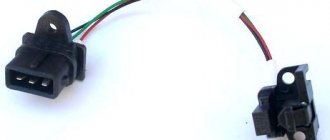
- Checking the ignition coil with a multimeter (tester) using the example of a Ural motorcycle coil
Ignition coil for motorcycle Ural and Dnepr
The other day I ran into a problem; my Ural motorcycle suddenly stalled, I had to ride home for about an hour. Having arrived, I began to think about what the problem was, I checked everything I could - everything turned out to be in working order. When I got to the ignition coil I encountered a problem, how to check the ignition coil with a multimeter on a Ural motorcycle? This is how this article turned out, in which we will look at the method of checking the Ural ignition coil and try to understand the reasons for the problematic operation.
Determining why the ignition coil heats up
The main function of the coil is to convert low voltage voltage, which comes from a generator or battery, into high voltage. There is a generation of high-voltage electrical pulses on the candles. The ignition coil connection diagram provides a certain operating mechanism: when the starter is turned on, thanks to the contact disk, an additional resistance is turned on, this leads to an increase in the current passing through the primary winding, and, as a result, the voltage of the secondary winding increases, which contributes to the reliable ignition of the working mixture.
Malfunctions of the ignition coil can be noticed by the following symptoms. First of all, if it has a high temperature when the engine is off. The cause of this symptom may be turning the key to the active position for a fairly long period with the engine turned off. The next alarming sign is a short circuit, when the engine does not start at all, resulting in a smell of burnt insulation and strong heating of the lock, as well as the starter. In this case, repair and replacement of the ignition coil is necessary.
To mainUnstable operation of the car also helps to understand that diagnostics are urgently needed. It begins to twitch when driving at speeds exceeding 60 km/h, and during a long stop, for example in a traffic jam, the spark may disappear altogether, then the ignition coil should be checked as soon as possible.
IGNITION FAULTS
With battery ignition, to identify the cause of the absence of a spark in the spark plug, when the ignition switch is turned on and the control light is on, it is necessary to sequentially check the spark plug, the tip of the high voltage wire, the breaker, the distributor and high voltage wires, the electrical wiring up to the ignition switch, the capacitor, ignition coil. If a spark does not jump directly from the high voltage wire to ground, then a sequential test is carried out as follows. First of all, make sure that there is a gap between the contacts of the breaker, that they are clean and tightly closed. Use your hand to lift the hammer away from the anvil. If a spark does not appear in the spark plug, then check whether the hammer is energized. To do this, use the end of a screwdriver to intermittently connect the hammer contact raised from the anvil to ground. When the hammer is not energized, determine the location of the electrical circuit break by sequentially connecting the breaker terminal, the ignition coil terminal connected to the breaker, and the second ignition coil terminal to ground through a test lamp. The absence of voltage in the latter case indicates an open circuit in the ignition switch. When the hammer is energized, the breaker is in good working order, but there is no spark in the spark plug, the capacitor or ignition coil is faulty. For motorcycles with magneto ignition (domestic motorcycles used for sports and motorcycles K1B, AVO-425, BMW-R-75), if there is no spark on the spark plug wire, check the breaker and distributor. If they are in order and there is no break or short circuit in the internal wiring, then the reason for the magneto failure is that the ignition coil winding is damp or broken or the magnets have become demagnetized. To inspect the parts (except for the breaker), the magneto is disassembled and element-by-element testing is carried out in accordance with the instructions for testing battery ignition parts. If a malfunction is not detected, but the magneto spark is weak, the magnets are magnetized. Magnetization in workshops is carried out with a powerful electromagnet, without which complete saturation of the magnets cannot be achieved. Checking the operation of the spark plugs.
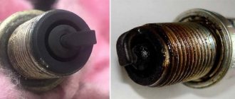
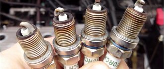
The suitability of a spark plug for use is determined by its external condition: the lower part of the insulator should be free of oil and soot, external cracks and other damage;
the gap between the electrodes should not be less than 0.4 mm
and more than 0.8
mm
. Damage and dirt on the top of the insulator will cause the spark plug to fail. It is necessary to check whether the insulator in the housing is swaying. A preliminary check of the spark plug is carried out in a well-known way: a spark plug with a wire attached to it is placed on the ribs of the cylinders and, by turning the engine crankshaft with the starting pedal, see if a spark jumps between the electrodes. This method is very inaccurate, since a spark at atmospheric pressure will jump even if the insulator is clean and if it is heavily covered with soot, however, if a spark plug with a soot-covered insulator is screwed into the cylinder, then starting will deteriorate and there may be interruptions in ignition during engine operation. Every driver should have a proven spare spark plug. If there is no spare spark plug, then the following test method can be suggested (Fig. 40). Some insulating material, for example, a strip of rubber, is inserted between the electrodes of the spark plug being tested, after which the spark plug is tested for a spark in the usual way. Damage to the insulator can be detected by sparking from the insulator to the housing inside or outside the spark plug. For a working spark plug, a spark will appear between the central electrode and the housing.
The most commonly observed cause of spark plug failure is the formation of soot on the bottom of the insulator. Soot is electrically conductive and can partially or completely short-circuit a high voltage current to ground. Obviously, if you do not remove the soot from the insulator, then cleaning the electrodes between which there is a spark gap will be useless and therefore the serviceability of the spark plug will not be restored. The dismountable spark plug is disassembled using ear wrenches, and its insulator is wiped with a rag soaked in gasoline. When using leaded gasoline or if blackness appears on the insulator that cannot be washed off by gasoline, clean the insulator with fine glass sandpaper. For a non-separable candle, the accessible part of the lower end of the insulator is cleaned with a piece of wood, a tip wrapped in a rag, glass sandpaper, and then rinsed with gasoline and dried. A badly neglected candle is cleaned by heating on a gas burner, electric stove, blowtorch, or fire. To ensure that “burning” causes less damage, the candle is heated from the lower end and the body is not brought to the glow temperature. Long-term heating at a lower temperature should be preferred over short-term heating at a higher temperature. When heated over a fire, the candle is placed on a tin shield, since in direct contact with the flame the insulator will become sooted. Traces of melting or soot may appear on the insulator of a completely serviceable spark plug due to a mismatch between the length of the threaded end or the thermal properties of the spark plug for the given engine. During operation, the spark plug must heat up so much that the oil that gets on the insulator and electrodes burns without residue. If the spark plug in the engine does not heat up enough, oil and soot will accumulate on the insulator and short-circuit the high voltage current to ground. On an overheated plug, the oil will burn very quickly, but due to the strong heating of its parts, the mixture will begin to ignite regardless of the appearance of a spark. The correct choice of a spark plug is to ensure that the insulator and electrodes are heated only to the temperature necessary to burn the oil and soot particles deposited on them. The length of the threaded end of the spark plug must correspond to the depth of the hole for it in the cylinder head. In fig. 41 shows three cases of installing a candle. The left candle, recessed in the hole, will not heat up enough and may become oily and covered with soot. The middle spark plug, the end of which is flush with the hole, is installed correctly. The right spark plug protruding into the combustion chamber may overheat. In addition, the protruding part of the thread will become covered with carbon deposits over time, which is why, when removing the spark plug, the thread of the hole in the cylinder head is damaged.
In fig. 42 shows spark plugs with different sizes of internal cavity. The larger the internal cavity and the longer the insulator skirt, the more heat the spark plug can absorb and, therefore, its temperature during engine operation will be higher. The larger the area of contact with the air of the upper part of the candle, the more thermally conductive its materials are, the more intense the candle is cooled. Based on these considerations, one can preliminary assess the thermal qualities of the spark plug and judge its suitability for a given engine. It is obvious that from those shown in FIGS. 42 candles, the left one will be hotter, and the right one will be colder.
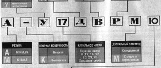
For domestic motorcycle spark plugs of the NA11-11 and NA11-10 brands, the last digits of the designation indicate the length of the skirt in mm
.
Therefore, the HA11-10 candle will be colder than the HA11-11 candle. The use of special motorcycle spark plugs of the NA11-11 and NA11-10 brands, as well as currently produced domestic and imported spark plugs with a heat rating from 125 to 225 (stamped on the body) should not cause them to fail due to inconsistency in thermal properties. Soot on the insulator will appear when using candles with a higher heat rating or shielded candles. Breaker adjustment.
Adjusting the breaker consists of setting the recommended gap between the contacts and caring for its parts. The gap between the breaker contacts recommended by the manufacturer is as follows:
For motorcycles M1A, K-125, IZH-350, IZH-49 For motorcycles M-72, BMW-R-51, BMW-R-66, BMW-R-51 For motorcycles K1B For motorcycles BMW-R-35 For motorcycles AVO-425
| 0,4-0,5 mm 0.4-0.45 |
If the gap is too small, the contacts burn from sparking; if the gap is too large, they are destroyed from mechanical damage, and wear of all moving parts of the breaker, in particular wear of the fiber of the hammer and cam, occurs faster. In addition, the spark becomes weaker. The contacts must be clean and, as tightly as possible, adjacent to one another, otherwise the reliability of the ignition operation will decrease. The cleanliness of the contacts is especially important for the K1B motorcycle when ignited from Magdino. The gap is adjusted using a feeler gauge when the contacts are completely open. To set the gap between the contacts on motorcycles M1A, K-125, IZH-350 and IZH-49 (see Fig. 47), loosen two adjacent screws 1
and
2
and, holding the hammer, move the contacts apart to the required distance, after which the screws are secured again.
On motorcycles M-72 (Fig. 43) and BMW-R-35, which have identically designed breakers, when setting the gap, loosen the upper screw on the anvil 1
and rotate the eccentric
2
until the required distance is established between the contacts
3
, after which the screw
1
.
If the cam protrusions of the M-72 motorcycle open the contacts at unequal distances, then the adjustment is made on the protrusion that creates less clearance. On the K1B motorcycle, the breaker (Fig. 44) is located under the flywheel. To set the gap, first loosen the locknut 6
on the anvil contact screw, and then by screwing or unscrewing the adjustable contact
5
, set the gap and securely lock the nut.
The gap is set on the AVO-425 motorcycle (Fig. 45) with magneto ignition in the same way as on the K1B motorcycle.
Caring for breaker parts is, first of all, keeping them clean. The breaker is washed with gasoline, carefully inspected and the hammer axis and the felt seal that supplies lubricant to the cam are moderately lubricated. Oily contacts are wiped with a clean cloth folded in half and placed over the dipstick or a strip of cardboard. To ensure that no fibers remain on the contact surfaces, a probe is inserted between them several times. Burnt contacts are cleaned with a thin file. In this case, contacts are restored temporarily. It is more advisable to remove the hammer and anvil from the platform and treat them with a whetstone, then the contact surfaces will be restored anew. Moving parts - hammer on the axle, cam during automatic advance (motorcycles IZH-350, IZH-49 and AVO-425), breaker platform (motorcycle M-72), breaker body (motorcycle BMW-R-35) - must rotate without jamming . On the M-72 motorcycle, check whether the distributor rotor is rubbing against the hammer, preventing its free movement. It is necessary to check the insulation and attachment of the wire to the breaker, as well as the reliability of the electrical connection of the conductors inside the breaker. The electrical circuit may be broken in the hammer itself (in motorcycles M1A, K-125, IZH-350 and IZH-49) due to a break in the foil plate on it or a loosening of the contact connection with the foil. Checking the ignition installation. Engines have constant or variable ignition timing. With constant ignition timing, the moment a spark appears in the cylinder remains unchanged for the entire range of engine crankshaft speeds - from low idle speed to maximum. With variable advance, the moment the spark appears can be changed automatically - by a centrifugal regulator (depending on the number of revolutions of the engine crankshaft) or mechanically - by the driver's hand. The ignition in the engine is set according to the data in table. 5.
Table 5
Data for installing the ignition for motorcycles
| Motorcycle brand | Piston position during installation | Total advance in degrees of crankshaft rotation or in mm piston stroke | Advance mechanism |
| M1A, K-125 | 4 mm to v.m.t. | 28°, 4 mm to v.m.t. | — |
| IZH-350, IZH-49 | 1 mm to v.m.t. | 30° | Centrifugal regulator |
| M-72 | 2 mm to v.m.t. | 53° | Manual |
| K1B | 4,5 mm to v.m.t. | 30°, 4,5 mm to v.m.t. | — |
| BMW-R-35 | In v.m.t. | 12 mm to v.m.t. | Manual |
| AVO-425 | 0,65 mm to v.m.t. | — | Centrifugal regulator |
If the ignition is set with a large deviation from the standards given in the table. 5, then the engine cannot be started and will not work. If the ignition is not set correctly, the engine can work, but starting it is difficult, the power it develops, as well as its service life, are reduced. If the ignition is set too early, counter-blows of the pedal during startup and metallic knocks in the engine are observed, even with a slight increase in load. Due to late ignition, the exhaust pipe heats up quickly, red-hot, shots are heard in the muffler, the engine speed increases slowly, and the engine does not develop full power. To check the accuracy of setting the ignition timing, it is necessary to perform the following operations: bring the piston to the top dead center. at the end of the compression stroke and then move the piston by the amount recommended by the factory, rotating the shaft in the direction opposite to its rotation when the engine is running; set the breaker to the position where the contacts begin to open and check that the moment the opening begins coincides with the position of the piston. To determine the compression stroke of a four-stroke engine, turn the crankshaft with the starting pedal or with your hand on the wheel when the gear is engaged on a motorcycle standing on a stand and monitor the valves: if the intake valve rises and falls, then the piston moves to the T.M.T., making compression stroke. As the piston continues to move, normal clearances should form between the pushrods and the intake and exhaust valves, confirming that the piston is near the TDC corresponding to the end of the compression stroke. If no gaps are formed, then the piston is mistakenly brought in. m.t., corresponding to the end of the release. This mistake is made quite often. In this case, the engine crankshaft is cranked a second time. Determining the compression stroke in a two-stroke engine is simplified, since it contains every c. m.t. is the end of the compression stroke. Installation of the piston in the T.M.T. produce
in the following way (Fig. 46).
Through the hole for the spark plug, a plate or piece of copper or aluminum wire is inserted into the cylinder and, turning the crank, the piston head is felt with it. For convenience, the wire probe is bent so that it accurately shows whether the piston is moving up or down. If the piston cannot be probed with a wire, then the cylinder head is removed. Pressing the wire against the piston, simultaneously rotate the engine crankshaft forward and backward by the wheel, engaging direct transmission, until the piston is in position. m.t. The wheel is turned not with a uniform force, but with light pushes, which make it possible to move the piston most accurately. Installing the piston in. m.t. by wire by eye or just by feeling its movement is not accurate enough. On the wire, flush with the beginning of the thread in the hole for the spark plug, make a mark with a knife or file that corresponds to the position of the piston in the hole. m.t., and then with light pushes the wheels try to move the piston. If the mark on the wire does not rise higher, it means that the piston is exactly in position. m.t. Then, on the wire upward from the existing mark, using a caliper or ruler, apply a second mark at a distance corresponding to the ignition timing of the given engine (Table 5). By rotating the wheel back, the piston moves from to. m.t. so that it is installed according to the newly applied mark. In the breaker, at this position of the piston, the contacts should begin to open. Determining the moment when contacts begin to open
with some skill, it can be done by eye, slightly turning the crank in one direction or the other.
The following three methods are much more accurate: 1) insert a strip of thin paper between the contacts; it is possible to pull it back when, due to cranking of the engine crankshaft, the contacts begin to open and stop clamping the piece of paper; 2) connect a portable light bulb in parallel to the breaker (like a capacitor) (Fig. 47), and turn on the ignition in the usual way. The light will blink when the contacts open, and when they are completely open, it will light up; 3) turn on the ignition and observe the control light. At the moment of opening the contacts, the glow of the light bulb intensifies somewhat, and when closed it weakens. Checking the ignition installation for two-cylinder V-shaped engines
(Fig. 48). In V-twin engines with an angle between the cylinders of, for example, 45°, in contrast to single-cylinder and two-cylinder engines with opposing cylinders, the firing in the cylinders alternates through an unequal number of degrees of crank rotation.
Let us assume that in the front cylinder I
the piston is in.
m.t. of the end of the compression stroke (Fig. 48, a), then, due to the fact that the connecting rods are mounted on one crank neck, in the rear cylinder II
the piston will be installed in the c.
m.t. end of compression, when the connecting rod journal describes an arc of 360° - 45° = 315° (Fig. 48, b). If you now rotate the crank so that the piston in cylinder I comes back to c. m.t. end of compression, then the connecting rod journal will describe an arc of 360° + 45° = 405° (Fig. 48, c). In other words, cylinder flares occur at 315° and 405°. The chopper cam for battery ignition and magneto in a four-stroke engine rotates twice as slow as the crank. Consequently, the contacts open respectively through 315°: 2 = 157.5° and 405°: 2 = 202.5°. For this purpose, the protrusions on the breaker cam are also located at 157.5° and 202.5°. A V-twin engine can only operate in conjunction with those breaker or magneto that are suitable for it according to the alternating openings of the breaker (in degrees). If you check the ignition setting for the front cylinder I
, then take into account that in the rear cylinder
II
the flash will occur after a short interval in degrees of crank rotation.
Consequently, in the breaker, the hammer is installed on protrusion I
of the cam, from which protrusion
II
is also spaced at a short interval in degrees.
In this case, the direction of rotation of the crank and the breaker cam is taken into account. An inexperienced driver should double check the ignition setting, i.e., set the ignition in the front cylinder, then turn the crank so that the piston in the rear cylinder is set to idle. m.t. compression stroke. If the opening of the breaker contacts coincides with the positions of the pistons in c. m.t. end of compression in both cylinders, which means that the ignition is set correctly and all that remains is to correctly connect the wires from the distributor to the spark plugs of the corresponding cylinders. The correct connection of the wires is checked by the position of the distributor or by a spark. In the first case, they ensure that the current-carrying part (rotor or commutator) supplies voltage to the wire of the cylinder for which the breaker contacts are currently open. In the second case, they look for which cylinder the contacts have opened and connect to it the wire from which the spark jumps to ground. The given instructions are used when checking the ignition installation of most well-known motorcycles. For some motorcycles, mainly domestic brands, we indicate some practical techniques that make this operation easier. For M1A and K-125 motorcycles, a wire probe is inserted into the cylinder through the hole for the decompression valve. Having felt the piston, take into account that its head is semicircular, and therefore the wire is lowered vertically in the same direction. It is more convenient to work with the breaker and observe the contacts not through the existing hatch, which impedes visibility and access, but by removing the entire right crankcase cover. The ignition timing is changed by moving the chopper. To increase the advance, its main plate is moved against the rotation of the cam, to reduce the advance - in the direction of its rotation. Before moving the plate with a hammer and anvil, loosen the two outer screws (see Fig. 47) 1 and 3 that secure it, and while moving, hold the breaker to prevent changes to the previously established gap in the contacts. Changing the gap also causes a change in advance. As the gap increases, the advance increases, and as the gap decreases, it decreases. Therefore, if, for example, to increase the advance, you move the breaker plate against the rotation of the cam, but neglect to reduce the gap, then the operation may be unsuccessful, since the decrease in the gap compensates for the movement of the hammer and the advance will not increase. The crank of the M1A and K-125 motorcycles is rotated with a wrench by the head of the bolt securing the anchor. This makes it much easier to move the piston into the desired position. Using a portable light bulb connected in parallel with the breaker (see Fig. 47), the beginning of the opening of the contacts is set so precisely that from the slightest turn of the cam, which does not cause noticeable movement of the piston, the light bulb immediately begins to blink and lights up. In the engine of the IZH-350 and IZH-49 motorcycles, the crank is rotated by rotating the wheel in direct gear. The ignition is set just 1 mm
before the piston arrives.
m.t. with the weights of the centrifugal regulator not dispersed and the cam turned against the direction of its rotation until it stops. The advance is automatically increased by a centrifugal regulator, so its action is checked by turning the cam by hand in the direction of shaft rotation. The cam should, springing, rotate at a small angle, pushing the loads apart. The cam, not held by hand, under the action of the springs, should easily return to the initial position of the late ignition. All other operations are performed in the same way as when checking the ignition of an M1A engine. In the M-72 motorcycle engine, the ignition cam is made together with the end of the camshaft, so the ignition installation operation is eliminated. But checking the ignition installation is necessary, especially for engines that have been in operation. They have unequal gaps in the breaker contacts. If the gaps are unequal, ignition in the right and left cylinders also occurs with unequal advance or retardation. The ignition installation is checked separately for the right and left cylinders. The detected difference in the ignition setting is eliminated by correspondingly cutting off the cam protrusions. The breaker platform must rotate in the body from lock to lock, precisely obeying the lever on the steering wheel. The crankshaft of the K1B engine is rotated by the flywheel, taking into account that the direction of rotation of the shaft is opposite to the direction of rotation of the rear wheel. Changes in ignition timing are achieved by turning the main magdino disk, which for this purpose has grooves at the points of attachment to the crankcase (see Fig. 44). To move the disk, loosen the bolts securing it. Using an electric light bulb to check the ignition timing is unacceptable, since the electric current will demagnetize the flywheel magnets and the magdino will fail. For the AVO-425 motorcycle engine, when installing the ignition (see Fig. 45), it is possible to rotate the magneto shaft attached to the crankcase with bolts 1
.
Due to the fact that the magneto has an automatic centrifugal-type advance regulator, it is possible to adjust the installed ignition by angular movement of the breaker pad 8
attached to the magneto with screws
5
.
For the convenience of adjusting the ignition, installation marks and a rectangular slot 9
for a screwdriver are made on the platform and on the inner surface of the breaker body, with which the breaker platform is turned.
Due to the fact that this engine, due to the high compression ratio, has very strong detonation, it is necessary to adjust the ignition by turning the breaker pad counterclockwise. As a result, it is possible to somewhat reduce detonation knocks, which reach critical levels when using low-octane motor gasoline. To set the gap at the breaker, use an adjustable contact screw 6
with a lock nut
7
.
Checking the capacitor.
The following capacitor malfunctions may occur.
1. Insulation breakdown and short circuit between plates
.
With this malfunction, the capacitor to ground shorts the primary winding of the high voltage coil and thus completely stops the ignition. 2. Broken connections inside the capacitor
.
Such a capacitor spontaneously disconnects from the breaker and ignition coil. The breaker contacts begin to spark very strongly, and the spark from the high voltage wire weakens, the engine cannot be started or it works with constant interruptions. 3. Electrical leakage or poor insulation between the capacitor plates
.
As a result, the spark is weak and irregular, starting the engine is difficult and it runs intermittently. Sparking in the contacts of the breaker with a good spark on the high voltage wire is a normal phenomenon, indicating a full charge of the battery or high electrical power of the magneto. To accurately check the capacitor, it is connected to a current network with a voltage of at least 220 V in
series with a lamp and an ammeter.
An approximate test can be carried out without an ammeter by connecting a capacitor in series with a 25 W
in a voltage circuit of 110 - 127 V.
If the light comes on, the capacitor is damaged. For a working capacitor, after briefly connecting it to the current circuit, a small spark jumps when the terminal approaches the body. Such a check does not exclude the possibility of interruptions in engine operation due to a defective capacitor. The capacitor cannot be repaired and, since it is an easily accessible and cheap part, if there is any doubt about its serviceability, it is replaced with a new one. Checking the ignition coil.
The ignition coil may fail prematurely due to mechanical damage, its installation on very hot parts of the engine (for example, under the front crankcase cover of the M-72 motorcycle engine), exposure to dampness or poor protection from water ingress in the absence of a metal case (ignition coils of K-72 motorcycles). 125, IZH-350, IZH-49, K1B and most types of magneto), leaving the ignition on when the engine is not running, checking the spark with a large spark gap.
Restoring the operability of ignition coils is only possible if they do not work due to dampness. The coil is dried by keeping it for several days in a dry room or heating it to a temperature not exceeding 100°. To check, the ignition coil is removed from the motorcycle and directly connected to the breaker assembly with capacitor and battery. This eliminates the possibility of damage to the wires and oxidation of the primary circuit terminals affecting the operation of the coils. At the moment the hammer is lifted from the anvil by hand, a spark of at least 6 mm
.
With a good coil, the spark can be much longer, but the spark gap should not be increased more than 10 mm
, so as not to cause irreparable damage to the insulation of the high voltage winding.
When testing a coil without a capacitor, the spark is extremely weak. To exclude the possibility of a defective capacitor affecting the operation of the coil, you should try two or three capacitors during testing. A coil that does not work despite replacing several capacitors is unusable. As a rule, a damaged coil cannot be restored. Checking the high voltage distributor.
The distributor does not work if it leaks high voltage current. Leakage occurs from the accumulation of coal dust on the surface and in cracks of carbolite parts or if these parts become damp. Therefore, the distributor parts are cleaned of coal dust and protected from water ingress. When metal parts in the distributor oxidize, the electrical contact in the high voltage circuit is practically not deteriorated. When checking the distributor rotor of the M-72 motorcycle, pay attention to the fact that there is no black mark rubbed with coals on its working surface, the metal plate and carbolite are smooth, do not have thresholds or other irregularities from wear. Unevenness will cause the coals to jump and the rapid formation of coal dust. The rotor surface, darkened by coal dust, is washed in gasoline and cleaned with fine sandpaper to remove the top layer of carbolite, into the pores of which coal dust has penetrated. A worn rotor is machined or replaced with a new one. For electrical testing, a high-voltage wire is brought to the central sliding contact of the rotor, which is not removed from the end of the shaft, the ignition is turned on, and the engine crankshaft is cranked. If a spark jumps between the wire and the central contact, the rotor is unusable and cannot be restored. Before checking, the distributor cap is washed with gasoline, dried and, without putting it on the breaker body, the middle terminal of the cap is connected with a wire to the ignition coil. Turn on the ignition and crank the engine crankshaft. If a spark jumps from the wires running from the outer terminals of the distributor to the spark plugs to ground, then the distributor cap is unusable. The high voltage carbolite terminals of the magneto are also checked. Often, despite the absence of external damage and coal dust, when water gets in they give a significant leak to the ground; Starting the engine is difficult and it runs intermittently.
| Previous page | table of contents | Next page |
What causes ignition coil malfunctions?
It is a coil pulse transformer consisting of two windings: the primary winding, which has a small number of turns of thick wire, and the secondary, consisting of many turns of relatively thin wire. In addition, each bobbin has an additional ignition coil resistance. Therefore, many malfunctions can occur simply due to a break in one of the coil windings , and a short circuit in the bobbin windings is also quite possible.
If the key is turned to the active state, but while the engine is not running, this leads to excessive heating of the insulation of the bobbin windings, and, as a result, it dries out and crumbles. Thus, the wires remain exposed, which contributes to the occurrence of a short circuit. In addition, the silicone from which the ignition coil tips are made is also subject to aging, which contributes to the occurrence of leaks and the engine “troits”.
Setting up contact ignition on Izh Jupiter - 5
Let's take a step-by-step look at how to set up contact ignition on this device:
- Align the piston of the desired cylinder: - insert a screwdriver into the cylinder - rotate the crankshaft while holding the screwdriver
- Take a ruler and place it next to the screwdriver.
- Rotate the crankshaft, holding the screwdriver down with your finger so that it is level. We find a dead point.
- Turn the crankshaft in the opposite direction (1.5-2 mm).
- A spark is generated when the cam opens, locate the two adjusting bolts.
- Take a light bulb with two contacts, connect one to ground, the other to the contact.
- Turn on the ignition switch.
- You need to find the moment when the light comes on (the moment it lights up, the start occurs), and when it goes out, the contact closes on the contrary.
- Turn off the ignition, do and adjust the same with the second cylinder
Ignition adjustment Izh Jupiter - 5
After all the adjustment manipulations are done, the turn comes for an operation called Izh Jupiter-5 - ignition adjustment.
It is better to produce from the following devices:
- Device K-25 - has an indicator head that fits into the holes for spark plugs or bushings and a knob with divisions from the tool
- Lamps 12 V, 2 W - with their help you can determine the moment of opening the necessary contacts of the breakers. The lamp must be connected to ground and the breaker terminal of the corresponding cylinder (for this, lamps with wires are used at the end), on which the ignition timing is adjusted.