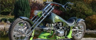
These designs are similar to both cool motorcycles and their “big brothers”, but longer. You can buy them in a store or make a bicycle with your own hands.
{ ArticleToC: enabled=yes }
From motorcycles they took a long frame and fork, and a large steering wheel. Thanks to the unique design, the center of gravity was shifted, making the vehicle more rolling. Thanks to this, the chopper can easily ride even on bumpy asphalt.
Advantages
In Russia they have been gaining popularity in recent years.
Additional advantages include the following:
- exquisite appearance;
- unique style;
- high comfort;
- wide tires, allowing you not to feel the unevenness of the surface;
- the possibility of electrification and turning it into a bicycle moto;
- available tuning;
- an unforgettable driving experience.
On the website https://megavel.ru/category/velosipedy-choppery/ you can get acquainted with the models and the price, which cannot be called low. How to be? You can do it yourself, and for reasonable money.
If you strictly follow the instructions below, which use parts from old bicycles and scrap materials, it is quite possible to make a vehicle with your own hands. It will turn out no worse than what the retail chain offers.
An old women's bike from the Wisp Raleigh brand is suitable for making a chopper, which will turn into a wonderful cruiser.
Required materials and tools
So, in order to make a chopper with your own hands, you need:
- welding machine, type Clarke 105EN;
- donor bike;
- durable steel pipes for making forks and extending the frame. The diameters of the pipes for the frame are selected so that two pipes of different diameters can be welded (this is simpler and more reliable than welded pipes of the same diameter),
- sheet steel 1.4 mm thick for hopper plates;
- 2 new chains that will be required for the enlarged frame. They need to be connected together;
- pipe bending machine. It is needed so as not to cut the elongated pipes at an angle, but to bend them, significantly changing the angles of the frame.
When you have prepared the materials and tools, you can start making a bicycle with your own hands, turning an ordinary model into a chopper.
Fork manufacturing sequence
Step 1: Which model to choose?
The Raleigh Wisp racing bike, taken as a basis, has an unusually shaped frame: the top tube goes from above to the rear hub, which is just to our advantage. It is advisable to preserve this feature. The seat can be installed on a double top tube.
You need to start making a structure with your own hands with a fork.
Step 2: Chopper Fork
First you need to choose the right one.
We start making a bicycle with our own hands by dismantling the old one, for which:
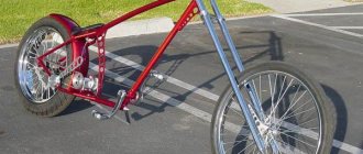
- remove the steering wheel with stem, steering column and unscrew the fork;
- We position the bike in such a way that the steering column is at the optimal height while riding, without worrying about the angles - they are not taken into account at this stage (see picture above). We measure the required length of the fork, i.e. the distance between the front wheel axle and the top of the steering column. Approximately this is 122 cm. The size is decent, but this is for a chopper - a long bicycle! We select a steel pipe, 2-2.5 meters long;
- We cut the pipe in half using an angle grinder, grind the ends on the grinder and place the pipes vertically.
Step 3: Fork Dropouts
For now, the fork consists of two pipes. In order for it to take on a normal appearance that allows you to install a seat, you will need two strong dropouts.
To make them with our own hands, we stocked up on sheet steel. The thickness of the plates should be approximately 3 mm.
The photo shows how the dropouts from a bicycle fork need to be applied to a steel plate to outline the outline for further fabrication. The blanks are cut from steel using an angle grinder.
The required accuracy should not be expected. Therefore, after the workpieces are cut out, they are brought to the desired size, clamped in a vice.
The edge must be processed carefully, since the contact between the surface and the wheel depends on this.
Next, in order to cut two completely identical sockets for the bushing axles, the two parts are clamped together in a vice. The tool used to do this is a grinding machine.
The nest is cut out carefully so that it is not large and this does not lead to the wheel popping out. The axle should sit tightly in the socket. Do not allow any play (pic below)!
When the dropout blanks are ready, they are welded to the fork using a magnetic holder.
Important: the dropouts do not need to be placed in the center of the pipe - they should be welded closer to the edge so that the spokes do not rub against the pipe.
At first, it is better to simply “grab” the dropouts by welding, and weld them securely after making sure that everything is installed correctly. At this stage, the time spent earlier on processing the edges pays off handsomely.
Step 4: make the top for the fork
For now, the future fork consists of two pipes to which dropouts are welded. This means it’s time to cut a thread on the top, which will require nuts with washers and M10 bolts. In any store such a kit is cheap.
You need to assemble the structure with your own hands, as shown in the figure, by welding each of the faces of the nut to the washer.
The bolt is no longer needed, so it can be unscrewed.
It’s time to weld the washer with the welded nut to the pipe (future fork)
Step 5: DIY chopper fork assembly
At this stage there are two pipes, to which dropouts are soldered on one side and nuts on the other. To further make the fork with our own hands, we cut off the old “leg” and make the base as flat as possible. We use cardboard as a template, on which we draw a semicircle around the pipe of the new fork.
Using an angle grinder, we cut out the crown for the new fork according to the template. We do this very carefully so that the shape is as correct as possible.
To determine the width of the fork, you need to attach a wheel to the dropouts. Having placed the rod with the crown between the pipes (it should stand level if everything is done accurately), we cut out three holes from another cardboard into which the pipes will go.
We recommend:
- Proper mountain bike position
- The benefits of exercising on an exercise bike
- Benefits of riding an exercise bike and cycling
We will use this template with three holes to make the base and top plates, after cutting the cardboard and giving it an aesthetic shape.
We start making a base plate with our own hands by cutting it out of a 1.4 mm thick steel sheet according to a template. On the steel we mark two holes for the fork legs and cut the sheet as in the photo.
After this, we weld the finished base plate to the fork crown. It is important to do everything carefully, avoiding contact with molten metal on the bearing race.
Now you need to make a stem, for which you can cut off the upper part of the existing stem or do everything from scratch if you have a steel pipe that fits the inner diameter of the fork stem. To do this, the pipe is cut at an angle of 45 degrees using the same angle grinder.
Now the pipe is shortened so that it fits the wedge and rod bolt. This completes the production of the takeaway. If you are using an existing stem, skip this step.
After the new stem is placed on the fork stem, place the stem and crown between the fork legs again, having someone hold it all down, or securing the assembly with a belt. It is important that the top nuts are located one inch below the top of the fork. If everything is centered, the plate needs to be welded to the fork.
Step 6: Second stage of making the fork
We have two pipes that are welded to the crown and stem, which means it's time to connect everything together. This requires a top plate. It is done by analogy with the basic one and the existing cardboard template. We mark on the sheet of steel the centers of the stem bolt and two legs. If bolts with a diameter of 10 mm are used, then a 15 mm drill will be needed to drill a hole in the center of the fork, since washers will be used during assembly.
The top plate is ready and needs to be bolted to the top of the fork.
The bolt retaining clamp will be discussed below. The fork is ready.
A wheel is attached to it and installed on the chopper, as shown above.
Now, to make riding comfortable, you need to upgrade the frame. And this is the next step.
Operating principle of the electronic ignition system
The latest generation of Minsk generators significantly increases the power of the electricity source. This ensures uninterrupted functioning of all elements of the system. In all speed modes, electricity consumers have reliable supply.
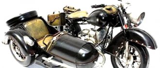
New generators differ not only in their functionality, but also in their structure. Different motorcycle models have different types of alternators. But they are similar in appearance, which allows you to attach them without matching the model.
The only thing to remember is that when changing the generator to another type, it is necessary to regulate all other elements.
Electronic ignition is non-contact. The design features of Minsk do not provide for the presence of a battery. The ignition system operates on the basis of GPT. The work uses a switch unit - stabilizer and an induction sensor.
A voltage stabilizer is used to regulate the amount of current supplied to lighting and sound signals. The switch and the stabilizer are not interconnected in their functions.
The Minsk ignition system works through the connection of such elements as:
- candle,
- voltage transformer;
- induction sensor;
- resistance;
- indicator lamps;
- wires
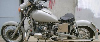
A properly configured ignition system is the key to ensuring that the motorcycle will start even in winter. The absence of a battery makes life easier for a motorcycle owner to some extent. There is no need to think about periodically recharging the battery. The Minsk motorcycle wiring diagram shows the relationship between individual elements.
Electrical circuit diagram for motorcycles Minsk
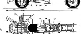
Motorcycle electrical circuit diagram 3.11211: 1 — front turn signal lamp A12-10; 2 — speedometer illumination lamp A12-1; 3 — high beam indicator lamp A12-1; 4 — side light lamp A12-4; 5 — low/high beam lamp A12-45+40; 6 — indicator lamp A12-1; 7 — neutral control lamp in the A12-1 gearbox; 8 — light switch, direction indicators with horn button; 9 — sound signal; 10 — relay-interrupter of direction indicators 25.3747; 11 — neutral control lamp switch; 12 - generator 43.3701010; 13 — rear direction indicator lamp A12-10; 14 — switch-stabilizer unit 262.3734; 15 — brake light lamp A12-10; 16 — side light lamp A12-5; 17 — brake light switch 13.3720; 18 — high-voltage transformer 2102.3705; 19 — spark plug A23B; 20 — handbrake brake light switch 13.3720; 21 - central switch; 22 - day-night switch and emergency ignition switch
Electrical diagram of a motorcycle 3.115 with an electronic ignition system
Electrical diagram of the Minsk motorcycle with battery:
1 - light switch and emergency ignition switch; 2 — handbrake brake light switch; 3 — right direction indicators with lamps A1 2-10; 4 — speedometer scale illumination lamp A12-1; 5 — headlight lamp A12-45+40; 6 — high beam indicator lamp A12-1; 7 — indicator lamp A12-1; 8 — control lamp for neutral in the gearbox; 9 — front side/parking light lamp A12-4; 10 — left direction indicators with A12-10 lamps. 11 — light switch, direction indicators and horn button; 12-ignition switch 058; 13 — spark plug A23B; 14 — neutral control lamp switch; 15 — sound signal; 16 — battery 6MT-5; 17 - fuse 8A; 18 — charger; 19 — ignition coil 2102.3705; 20 — relay-interrupter of direction indicators 25.3747; 21 — block BKS 262.3734; 22 — foot brake brake light switch; 23 — brake light lamp A12-10; 24 — rear marker/parking light lamp A12-5; 25 - generator 43.3701
Electrical diagram of motorcycles M-103, M-104, M-105, M-106: 1 - ignition switch; 2 — speedometer scale illumination lamp A6-1 (only on M-105, M-106); 3 — headlight lamp A6-32+21 or A6-32+32; 4 — side light lamp for headlight A6-2; 5 — sound signal S-34; 6 — light switch with sound signal button P-25 or P-200; 7 — ignition coil KM-01, IZH-56 or B-300; 8 — brake light switch (only on M-105, M-106); 9 — generator G-38, G-401, G-411 or G-421; 10 — brake light lamp A6-15 (only on M-105, M-106); 11 — rear side light lamp A6-3
Electrical circuit diagram for motorcycles Minsk MMVZ 3.111
Frame making
Step 7: First Stage
To cut the frame, it must be turned over and secured.
After some actions, the carriage became closer to the front of the bike. Now the frame needs to be lengthened.
We set aside the double top tube, which will look good on a chopper.
It is better to make a mock-up of the future frame before starting assembly in order to correctly place the wheels and determine the desired height of the frame. To do this, it is enough to support the carriage and lengthen the frame using thin pipes.
In the variant under consideration, the top tube turned out to be located a little low, so it had to be bent so that the saddle was at the required height. This must be done carefully so as not to break the pipe.
Well, if this happens, welding will help correct the situation.
If the design is satisfactory, you can move on to the next step, in which the frame is lengthened using steel pipes placed in the gap between the carriage and the two pipes running from the seat tube down.
This is where you will need a model to measure the length of two pipes. Because the angle of the down tube changed, it was necessary to make a bend near the bottom bracket. A pipe bender was used for this.
For now, the seat tube remains dangling, not secured to anything, so that’s what needs to be addressed.
We will again use the cardboard as a template to make another plate of sheet steel, which will be welded to the top of the horizontal pipes under the seat tube.
So the strength of the connection between the new two pipes and the rear ones will be increased. After this, the seat tube is welded to the plate.
The top tube was left dangling.
Another plate made of steel, and a socket made with a grinder in the seat tube, into which it must be inserted and welded, thus increasing the strength of the connection and reducing the load on the weld.
All that remains is to weld the two upper pipes to the steel plate, and they will stop hanging around.
Step 8: Stage two of making the frame
All that remains is to strengthen the frame structure. This can be done using another steel pipe, welding it between the carriage and the top pipe. This makes it possible to change the location of the seat tube, which is currently directed towards the rear of the frame.
Again, using the template, we make a plate and weld it to our pipe: lightly at first, and after selecting the angle, finally. The pipe should not touch the carriage axle. It should not go deep into the carriage.
This is what a finished frame looks like, made in-house for a chopper.
Step 9: How to make a saddle for a chopper?
A plank structure is suitable. In order to make it soft, we use foam material, and for aesthetics we use leather.
The two boards are fastened together using bolts. In the bottom you need to drill two holes through which the seat will be attached to the plate. It must be securely fixed using bolts and nuts.
A construction stapler will help secure the upholstery material with staples.
The leather is also stapled to the seat.
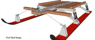
How to properly tension and adjust the track on a Buran snowmobile
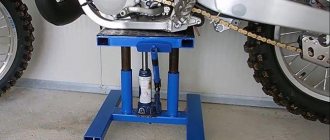
Before the start of the season, when snow has already fallen and a snowmobile ride is expected, it is necessary to check and adjust the track tension. The same procedure is carried out immediately after purchasing the unit.
In this case, simply lifting and checking the gaps is not enough; everything must be thoroughly checked. You can ask for help from a snowmobile service, but anyone who has such equipment should be able to do it themselves. The whole procedure will take approximately an hour to two, and in the end you will be one hundred percent confident in your transport. The process has several steps, each of which we will look at in more detail.
Check the integrity of the springs
The balancer springs must be intact; for normal operation of the track and maintaining the required tension, their long ends are located in the middle slots of the combs welded to the snowmobile frame itself.
Using these components, the track tension of the Buran snowmobile is adjusted depending on the quality of the snow cover:
| snow cover | location of springs |
| deep and loose | in the rear slots |
| compacted, knurled track | in the front slots |
Check the wear of the slip linings
Checking for wear of this component is carried out by completely dismantling them. Immediately remove the rear suspension, then come the pads themselves, you need to pry them off with a screwdriver and unscrew the bolts.
The removed runners are placed side by side and looked for defects, these could be:
The procedure for making the steering wheel
Step 10: Handlebar for a Homemade Chopper
There are three ways to install it:
- install the old one. But it may not fit the configuration (ram's horns, for example);
- do it yourself if there are steel pipes left. You can bend it with a pipe bender or cut it and weld it into the desired shape;
- choose one that suits the shape.
But first you need to make or select a donor lock. If one is found, mounting is not difficult.
This is shown in the photo.
Finally, you need to install the fastening clamps on the previously made top plate.
Weld them to the plate.
Also weld the clamp and insert the steering wheel into the mount. The steering wheel mount is adjustable.
Examination exercises canceled on 1 April 2022
Stop for safe boarding and disembarking of passengers
CANCELED FROM APRIL 1, 2022
Description of the exercise
• drive along the designated lane (Figure 6); • give a turn signal with your left hand and perform a lane change maneuver to the stopping place so that the projection of the left side of the motorcycle crosses the control line; • stop at a distance not exceeding 30 centimeters from the “STOP” line and not exceeding 30 centimeters from the marking line along the projection of the right side of the motorcycle, leaning on the ground with your right foot; • engage neutral gear and, holding the motorcycle motionless, lower your left foot to the ground; • continue driving, crossing the “STOP” line. The time it takes to complete an exercise element should not exceed 15 seconds.
Figure 6 Stop for safe boarding and disembarking of passengers
Recommendations
Reach a comfortable speed. Try to signal with your left hand in advance, so that by the time the maneuver begins, both hands are already on the steering wheel. Before maneuvering, disengage the clutch. When entering a parking space, steer with your feet, not the steering wheel. Just like on a snake. Before braking, move your body slightly to the right. This will allow you to stop using your right leg. Don't apply the front brake too hard.
Exercise “Dimensional Eight”
according to the regulations in the period from 2017 to 2022. Canceled April 1, 2021
Description of the exercise
Move along a given trajectory (Figure 7). The execution time should not exceed 35 seconds.
Figure 7 Dimensional eight
Reliable brakes
Step 11: Brake System
If you planned to use wheels from a donor bike, there may not be any problems. If the wheels, for some reason, are not satisfactory, and you want to replace them with more stable ones, for example, you need a different suspension.
When carrying out welding work, be sure to cover the tire with a damp cloth to avoid damaging it.
It is important to calculate exactly where the caliper brake will be located, weld the plate onto the rear triangle seatstays, checking that the mounting hole is located in the center.
Before cooking completely, check the operation of the clamp brake again.
This is what it should look like. The brake lever will work just fine from an old bicycle.
Malfunctions in electrical equipment
- Burning of contacts - occurs due to a broken connection of the terminals or breakdown of the capacitor. It is necessary to replace the capacitor and clean the contacts.
- Weak spark. Eliminated by replacing the spark plug. If it doesn’t help, you should look deeper for reasons.
- The rotor clings to the stator. Eliminated by replacing the bearing.
- Damage to winding insulation. The result will be no spark. If this problem occurs on the road, you can try to swap the terminals and get to the garage that way. In this case, the motorcycle will have to be started while running.
Assembly and testing
Step 12: Final Assembly and Testing
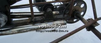
The difficult but interesting work of making a chopper has come to an end. All that remains is to carry out tests. It’s easier to convert the bike into a single-speed one, for which you will need to buy a single-speed adapter.
They can easily replace the old gear system. It was already mentioned at the beginning that a chopper bicycle is much longer than a regular bicycle, so you will need two chains. They are connected together.
Step 13: Completing the Assembly
A self-made bicycle is disassembled to remove welding spatter, and the fork and frame are painted in the preferred color. Bearing rings must be protected from paint during work, like other threaded connections.
It is more correct to apply the paint in a thin layer - this way you will make the paint even, without drips. It is better to then apply a second coat of paint.
Step 14: Possible Design Changes
If the model gets bored, you can disassemble it and make changes to the design, cutting off, for example, the back part.
Step 15: Align the Back
Then take the rear end of a small mountain bike.
Here again you need an angle grinder to sand down the extra parts of the frame.
Step 16: Correctly installing the extension lower pipes
Two pipes are cut so that they can be welded to the frame, lengthening the latter.
Malfunctions in electrical equipment
- Burning of contacts - occurs due to a broken connection of the terminals or breakdown of the capacitor. It is necessary to replace the capacitor and clean the contacts.
- Weak spark. Eliminated by replacing the spark plug. If it doesn’t help, you should look deeper for reasons.
- The rotor clings to the stator. Eliminated by replacing the bearing.
- Damage to winding insulation. The result will be no spark. If this problem occurs on the road, you can try to swap the terminals and get to the garage that way. In this case, the motorcycle will have to be started while running.
All of the above malfunctions can be prevented if you constantly monitor the condition of these elements. As you know, prevention is cheaper than repair.