Engine K-750 824 cm3. Result.
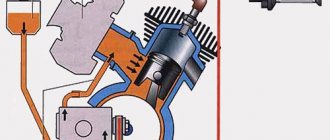
In general, a similar unit arrived for repairs in the spring. A man bought a whole motorcycle and, according to the seller, it was the best engine in the World. In brief: cylinders with sawn-off skirts, piston ends flush with the planes of the cylinders, displacers on the heads sawn off, 2.5 mm thick spacers under the heads. I didn’t spill the combustion chambers, but we can roughly estimate what we learned. Let's take the volume of the combustion chamber of the stock K-750 engine to be 72 cm3 (With all the standard and 79 pistons in this version, the compression ratio is 6.3. This is the best indicator of the volume of the combustion chambers and the compression ratio that I was able to get from the standard one, practically, the engine is 3.95×3.95×3.14×7.8=382 (382+72)÷72=6.3). The cylinder diameter is 8.2 cm. Accordingly, the radius is 4.1 cm. The piston stroke is 7.8 cm. The working volume of the cylinder: 4.1 × 4.1 × 3.14 × 7.8 = 411.71 cm3. The height of the displacer of the K-750M head is 0.5 cm. The volume occupied by the displacer: 4.1×4.1×3.14×0.5÷2=13.2 cm3 (Here 2 is half, in reality the area of the displacer is slightly larger. Let’s take half for simplicity.) “ Let us take the shortfall at TDC of the piston end to the cylinder end to be 6 mm = 0.6 cm. The volume occupied by the piston in this case is: 4.1 × 4.1 × 3.14 × 0.6 = 31.67 cm3. Volume occupied by a standard gasket with a thickness of 0.5 mm (0.05 cm): 4.1 × 4.1 × 3.14 × 0.05 × 2 = 5.28 cm cube ( 2, again to simplify the calculations, we will accept conditionally, since there is still a volume above the “cylindrical part” of the gasket ) Volume occupied by a “custom” gasket with a thickness of 2.5 mm (0.25 cm): 4.1×4.1×3.14×0.25×2=26.39 cm3. Volume of the combustion chamber “custom” = volume of the combustion chamber standard + volume occupied by the displacer - volume occupied by the piston - volume occupied by the standard gasket + volume occupied by the “custom” gasket: 72 + 13.2-31.67-5.28 + 26.39 = 74.64 cm3 . Now the compression ratio of such a cylinder is: (411.71+74.64)÷74.64=6.5159 Do you need further comments? Those. at a low compression ratio, detonation will be present in such a cylinder. It was precisely the evidence of the presence of detonation in the engine I disassembled that I saw - characteristic ring marks, or “rubbing,” on the cylinder walls. And on one of the pistons there was a broken partition between the rings! There were also scuffs both on the cylinders and on the piston fire zones, especially on their parts protruding from the cylinder. Why is this option of boosting lower valve engines not acceptable?
Those. when the piston protrudes beyond the edge of the cylinder, all the charm of a Ricardo-type combustion chamber, which is best for mixture formation in lower-valve engines, is lost. This illustration also confirms this. If the end of the piston were, as intended by the engineers, flush with the edge of the cylinder, then the compression ratio in this case would be: (411.71+72)÷72=6.7182 And in the case of trimming the planes of the heads, even more (as the literature advises on the preparation of M-72 motorcycles for competitions). And instead of these GAZ-51 pistons, isn’t it possible to find something more suitable? Less archaic and lighter? Yes, in your case, with a high degree of probability we can say that it was the deton that killed the crankshaft.
Chapter two
MOTORCYCLE POWER PLANT
The power plant of a motorcycle includes the engine and the lubrication, power and ignition systems that serve it. The motorcycles of the Kiev Motorcycle Plant are equipped with two models of four-stroke carburetor engines: K-750 with a side-bottom valve arrangement (for models K-750M, MV-750, MV-750M) and MT-801 with an overhead valve arrangement (for motorcycles K-650, MT-9, MV-650).
The design of the K-750 and MT-801 engines is discussed sequentially in the book.
ENGINE K-750 MOTORCYCLES
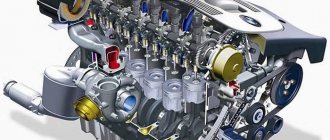
Engine K-750, longitudinal and transverse sections of which are shown in Fig. 6 (see incl.), two-cylinder, four-stroke, lower valve, air-cooled, with cylinders arranged horizontally (at an angle of 180°), with a displacement of 746 cm3, is a road-type motorcycle engine.
The engine consists of a crank mechanism, gas distribution and crankcase ventilation mechanisms and a lubrication system. The crankcase contains a 6-volt DC electric generator, a distributor chopper and an ignition coil.
Crank mechanism of the K-750 motorcycle engine
| Rice. 7. Crankshaft (crank) of the K-750 engine: 1 - rear axle; 2 - cheek; 3 and 8 — connecting rods; 4 - timing drive gear; 5 and 13 - oil traps; 6 — front axle; 7 - roller bearing; 9 – bushing of the upper head of the connecting rod; 10 — roller bearing separator; 11 — crank pin; 12 — oil trap fastening screw; 14 - rear main line |
The crank mechanism converts the linear, reciprocating movement of the pistons into the rotational movement of the crankshaft. This mechanism consists of a crankshaft 28 (Fig. 6), connecting rods 23, pistons 18 and cylinders 3 mounted on the crankcase 47.
The crankshaft is installed inside the crankcase on ball bearings 69 and 70. Above it is the camshaft 33.
Cylinders 3 are attached to the sides of the crankcase on studs. At the front, the crankcase has a blank wall with slots for bearings, and at the back it is closed by a round housing cover 49 for the rear crankshaft bearing.
At the rear of the crankcase there is a flywheel chamber 30, which is a connecting link with the gearbox housing.
In the front part of the crankcase there is a chamber in which there are gas distribution gears 39 and 43 and a generator drive gear 37. This chamber is closed with a cast lid 36.
At the top of the crankcase there is a boss on which a generator 35 is installed, secured with a clamp 6.
From below, the crankcase cavity is closed with a ribbed stamped pan 55 with a cork gasket 48.
To attach the crankcase to the motorcycle frame, it has two through holes a and b. An aluminum spacer tube with rubber O-rings is pressed into hole b to prevent the oil in the crankcase from leaking out.
Oil is poured through the filler hole, closed with a 6O plug with a dipstick, and goes down through the hole in the sump 55, closed with a plug 52.
At the bottom of the crankcase there is a boss with a machined plane for installing an oil pump that supplies lubricant to the crankshaft shafts, the left cylinder and the distribution gears through the oil line channels.
The engine crankshaft (Fig. 7) consists of two axles 1 and 6 with journals for support ball bearings, a cheek 2, two fingers 11 and oil traps 5 and 13.
The shaft parts are connected by a press fit with the elbows mutually positioned at an angle of 180°. The fingers 11 have cavities and radial channels for supplying lubricant to the connecting rod roller bearings.
| Rice. 8. Parts of the piston group of the K-750 engine: 1 - piston; 2 — compression rings; 3 — oil scraper rings; 4 — piston pin; 5 - retaining ring; a - the bottom of the piston; b - skirt; c — hole for a finger; g - thermal insulation groove; d - groove for compression rings; e - grooves for oil scraper rings |
The connecting rods together with the crankshaft form an integral structure, since they cannot be removed without unpressing the crankshaft. In the lower heads of the connecting rods there are single-row roller bearings 7 with cages. The outer ring of the roller bearing is the hardened surface of the connecting rod head, and the inner ring is the surfaces of the fingers 11. Bronze bushings 9 are pressed into the upper heads of the connecting rods.
The drive timing gear is installed on the journal of the front axle of the crankshaft, and a flywheel 30 is installed on the conical shank of the rear axle (Fig. 6).
The pistons of the K-750 engine (Fig.) are cast from a special aluminum alloy with minimal volumetric expansion when heated.
The main parts of the piston are the bottom a, skirt b and bosses, made in the form of bosses inside the piston and reinforced with ribs connecting them to the bottom.
On the surface of the piston at the bottom there are four annular grooves: the upper one is thermally insulating, serves to remove heat and prevent burning of the piston rings, two grooves d are for installing compression rings 2 and groove e is for installing the oil scraper ring 3. A similar groove is for the second oil scraper ring located in the lower part of the piston skirt.
Two oil scraper rings, which discharge excess oil from the cylinder surface into the crankcase through holes located along the perimeter of the grooves, significantly reduce engine oil consumption.
The piston rings are made of gray cast iron, subjected to special heat treatment, ensuring the elasticity of the rings in the range of 2.9-4.3 kgf for compression rings and 2.3-4.3 kgf for oil rings. The locks in the rings are straight, with a gap in the free state within the range of 9-13 mm, and in the working position in the cylinder 0.25-0.5 mm.
To avoid gas breakthrough, the ring locks must be offset during installation. The pistons are connected to the upper heads of the connecting rods using steel, hardened and polished on the outer surface of the piston pins 4. From axial movement, the piston pin is secured by two spring retaining rings 5 installed in the annular grooves of the piston bosses.
The K-750 engine cylinders, having the same design, differ in the placement of the intake and exhaust valves and are therefore not interchangeable. They are cast from special alloy cast iron and have a carefully machined and polished working surface. The outer surface of the cylinders has fins for cooling. Channels are cast in the cylinder body for
intake of the working mixture and exhaust gases. The channel openings at the outer ends of the cylinders are closed by valves installed in the guide holes extending into the cavities of the valve boxes cast integrally with the cylinder flanges.
The cylinder flange is attached to the engine crankcase with six studs, and the part of the cylinder protruding beyond the plane of the flange fits inside the crankcase, centering the cylinder in the mounting hole.
The outer plane of the cylinder is carefully machined to connect to the cylinder head and has eight threaded holes. The left engine cylinder has an annular inlet on the flange plane with three holes extending onto the working surface of the cylinder to supply lubricant to the cylinder mirror from the oil line. The mirror of the right cylinder does not have a lubricant supply and is lubricated by splashing.
The cylinder head is cast from aluminum alloy and has fins for better heat dissipation. A shaped combustion chamber is cast inside the head, in the upper part of which there is a threaded hole for a spark plug. The head is attached to the outer plane of the cylinder with eight bolts. An alloy shaped gasket is placed between the end of the head and the outer plane of the cylinder.
contents .. 1 2 3 4 ..
MY MOTORCYCLE
For normal engine operation, there must be an oil film on all its rubbing surfaces created by the lubrication system. The K-750 engine uses a combined lubrication system. It allows some parts to be lubricated with oil under pressure, and some - by splashing and oil mist formed in the crankcase when the engine crankshaft rotates.
The gear oil pump is installed in the lower part of the engine crankcase and, as mentioned above, is driven by the spiral spur gear 20 of the camshaft. Pump housing 1 is attached to the crankcase boss plane with two bolts and is closed from below with a flat cover with a hole through which oil is sucked in from reservoir 5. A strainer 4 is installed on the cylindrical protrusions of the cover mounting bolts, covering the oil pump housing and performing coarse filtration of the oil sucked in by the pump from engine crankcase.
Lubrication diagram for the K-750 engine: 1 – oil pump housing; 2 – drive gear; 3 – driven gear; 4 – oil pump filter; 5 – oil reservoir; 6 – filter (mesh); 7 – crank pin; 8 – oil catcher; 9 – oil pocket; 10 – oil channel; 11 – connecting rod; 12 – drilling in the valve box; 13 – drilling in the left cylinder; 14 – piston oil scraper ring; 15 – hole for lubrication of the piston pin; 16 – filler plug; 17 – oil channel; 18 – oil pump housing gasket; 19 – drain plug; 20 – drive gear; 21 – oil pump drive gear; 22 – drive gear coupling; 23 – oil pump outlet; 24 – oil channel to the rear bearing; 25 – oil drain channel; 26 – crank seal; 27 – rear bearing housing; 28 – oil pump inlet; 28 – oil pump inlet; 29 – radial hole in the crank pin; 30 – rear support ball bearing of the crankshaft; 31 – recess for lubrication of the oil pump drive gear; 32 – oil pipe; 33 – front support ball bearing; 34 – recess in the bearing housing; 35 – oil pipe; 36 – drain hole; 37 – main oil line; 38 – oil channel of the front bearing; 39 – annular groove; 40 – recess for oil injection
Oil from the pump body, pumped by spur gears 2 and 3, enters the oil line pipe through outlet 23, which is connected to two vertical channels 24 and 38, supplying it under pressure to oil traps 8 of the engine crankshaft. Under the influence of the centrifugal force of rotation, solid particles are discarded from the oil in the oil catchers, and the purified oil enters the roller bearings of the lower connecting rod heads through holes in the crankshaft pins and radial drillings. In this case, excess oil is thrown into the internal cavity of the crankcase and sprayed onto the surfaces of the cams and pushers of the gas distribution mechanism and onto the working surfaces of the cylinders, lubricating the bottom of the left and top of the right cylinder mirrors. In the right cylinder, oil from the upper part of the mirror lubricates the lower part by gravity, and in the left cylinder, additional oil is supplied to lubricate the upper part of the mirror. Directly from the oil line through inclined channel 17, oil under pressure is supplied to the annular groove under the flange of the left cylinder, and from there through three holes it flows to the upper part of the mirror. Part of the oil supplied through a vertical channel to the front crankshaft oil trap, through the annular groove 39 under the front bearing housing and tube 32, flows onto the surface of the teeth of the drive distribution gear and, when rotating, lubricates the teeth of the camshaft driven gear and the generator drive gear. The oil mist generated during the rotation of the timing gears settles on the friction surfaces of the front camshaft bearing and breather and provides their lubrication. Excess oil flows down and returns through the hole to the engine crankcase. The oil mist lubricates the pushers and their guides, from where the settled oil particles penetrate the chambers of the valve boxes of the cylinders, lubricating the rubbing surfaces of the pushers, springs and valve stems. Excess oil flows from the valve boxes into the crankcase through drilling 12. Lubrication of the piston pins and piston boss holes is ensured by the penetration of oil mist through holes 15 in the connecting rod heads. Lubrication of the rear bearing of the gas camshaft is provided by oil flowing from the walls and entering channel 10. Fresh oil is added to the engine lubrication system through a filling hole closed by a plug 16 with a dipstick, on which marks are marked indicating the maximum and minimum permissible oil level, and the drain used oil - from the system through the drain hole of the pan, closed with plug 19.