Coils B-300 and 2112.3705 are designed to work in “classic” ignition systems powered by an alternator G-401, G-411 and G-421. Such coils were installed on motorcycles K-58, “Kovrovets-175A”, “Kovrovets-175B”, “Kovrovets-175V”, “Voskhod”, “Voskhod-2” and motorcycles of the Minsk motorcycle plant M-103, M-104, M-105, M-106 and MMVZ-3.111.
Coils B-300B and 2102.3705 operate in contactless electronic ignition systems with generators G-427, 43.3701 and 80.3701. They were installed on motorcycles “Voskhod-2M”, “Voskhod-3″, Voshod-3M-01”, “Owl”, “Farmer”, “ZDK-175-4ShP” and motorcycles “Minsk” -MMVZ-3.115, MMVZ-3.112, MMVZ-3.113.
THE CAUSE OF THE BAD SPARK ON THE PLUG WAS AN INSUFFICIENTLY SEALED IGNITION COIL B-300. HOW TO CHECK IF THE COIL IS OPERATING AND CAN IT BE REPAIRED?
The presence of such a defect is easily verified. After drying the coil, sparking is restored. We offer a simple repair method. The gasket under the cover is replaced with a homemade one cut from thin rubber (for example, a tube from a bicycle tire). To ensure that the lid is tightly and reliably pulled to the body, install bracket 1 made from a steel rod with a diameter of 4-5 mm (Fig. 5.29).
Place a cracker 2 under it, made from the thinned part of the lid made of solid electrical insulating material. Secure the bracket with strap 3. Now the coil will not be afraid of moisture.
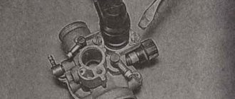
PROVIDE THE DATA OF THE DR-100 THROTTLE FOR THE “VOSKHOD-2” MOTORCYCLE. WHAT SHOULD BE THE WINDING RESISTANCE?
The DR-100 throttle core is assembled from non-standard strips 41 mm long and 0.5 to 1.0 mm thick. Thus, its cross-section (under the winding) is 7x8.6 mm. The inductor winding consists of 240 turns of PEV-2 wire with a diameter of 0.64 mm (copper). Winding resistance is 0.5-0.7 Ohm. inductance 2.3-2.6 Henry.
WHAT TO DO IF LIGHTING LAMPS FREQUENTLY BURN OUT?
With a correctly assembled motorcycle electrical circuit, the lamps burn out due to a malfunction of the P200 light switch or a breakdown in the connections between the headlight lamp and the socket due to oxidation of the lamp contacts. P-200 switches are not reliable, so owners of Voskhod motorcycles are recommended to slightly alter the electrical circuit by including a two-pole toggle switch TP1-2 and a DR-100 throttle (used on Voskhod-2), as shown in Fig. 5.30.
You can make the throttle yourself. 245 turns of PEV-2 wire with a diameter of 0.64-0.69 mm must be wound onto an open core with a cross-section of 0.65-0.7 cm 2 made of transformer iron. After alteration, lamp burnout for the above reasons is excluded.
THE SOUND SIGNAL TYPE 12.3721 INSTALLED ON MOTORCYCLES “ZDK” MAKES A HAZZY AND WEAK SOUND. IS THERE A WAY TO EQUIP VOSKHOD WITH A MORE POWERFUL HORN?
To do this, between terminal “01” of the BKS unit and “ground” you must connect an electrolytic capacitor (or a battery of capacitors) with a total capacity of at least 2000 microfarads, an operating voltage of at least 20 V. (“minus” to “ground”) After this, instead of signal 12.3721 You can install almost any car or motorcycle DC signal - S-39, S-205, S-304. It is best to place the capacitors under the filter air intake cover.
If the signal stops working, most likely the cause will be a break in the KD 202 diode connected between terminals “02” and “01” of the BKS unit. To eliminate the defect, it is enough to strengthen the diode outside the block (Fig. 5.31).
Generator Voskhod G-427
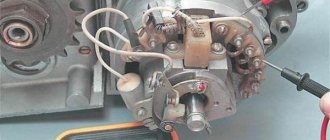
Generator G-427 alternating current with excitation from a permanent magnet with an inductive sensor of the electronic ignition system. In the grooves of the stator, assembled from stamped electrical steel plates, eight coils are placed, which form four independent circuits: – power supply to the ignition storage capacitor; – lighting and sound signal; – direction indicators; – brake signal.
Voltage regulation in the circuits of lighting loads is carried out according to the principle of parametric regulation, i.e. The winding data of the generator are selected in such a way that as the rotor speed increases, the voltage at the generator terminals changes within certain limits for a certain load. Attaching the generator stator to the engine crankcase provides adjustment of the ignition timing.
On the generator stator cover there are terminals: – charging coils of the power supply circuit for the Voskhod ignition storage capacitor; – direction indicators; – brake signal; – lighting; – sensor.
Which are marked accordingly: >, >, >, > and >.
The sensor is mounted on the generator stator cover using screws.
Generator rotor
The generator rotor with the sensor rotor located on it is mounted on the right axle axis of the engine crankshaft with a bolt and is secured against rotation by a key.
PROVIDE THE WINDING DATA OF THE VOSKHODOV IGNITION COILS.
Coils B-300 and 2112.3705 are designed to work in “classic” ignition systems powered by an alternator G-401, G-411 and G-421. Such coils were installed on motorcycles K-58, “Kovrovets-175A”, “Kovrovets-175B”, “Kovrovets-175V”, “Voskhod”, “Voskhod-2” and motorcycles of the Minsk motorcycle plant M-103, M-104, M-105, M-106 and MMVZ-3.111.
Coils B-300B and 2102.3705 operate in contactless electronic ignition systems with generators G-427, 43.3701 and 80.3701. They were installed on motorcycles “Voskhod-2M”, “Voskhod-3″, Voshod-3M-01”, “Owl”, “Farmer”, “ZDK-175-4ShP” and motorcycles “Minsk” -MMVZ-3.115, MMVZ-3.112, MMVZ-3.113.
THE CAUSE OF THE BAD SPARK ON THE PLUG WAS AN INSUFFICIENTLY SEALED IGNITION COIL B-300. HOW TO CHECK IF THE COIL IS OPERATING AND CAN IT BE REPAIRED?
The presence of such a defect is easily verified. After drying the coil, sparking is restored. We offer a simple repair method. The gasket under the cover is replaced with a homemade one cut from thin rubber (for example, a tube from a bicycle tire). To ensure that the lid is tightly and reliably pulled to the body, install bracket 1 made from a steel rod with a diameter of 4-5 mm (Fig. 5.29).
Place a cracker 2 under it, made from the thinned part of the lid made of solid electrical insulating material. Secure the bracket with strap 3. Now the coil will not be afraid of moisture.
PROVIDE THE DATA OF THE DR-100 THROTTLE FOR THE “VOSKHOD-2” MOTORCYCLE. WHAT SHOULD BE THE WINDING RESISTANCE?
The DR-100 throttle core is assembled from non-standard strips 41 mm long and 0.5 to 1.0 mm thick. Thus, its cross-section (under the winding) is 7x8.6 mm. The inductor winding consists of 240 turns of PEV-2 wire with a diameter of 0.64 mm (copper). Winding resistance is 0.5-0.7 Ohm. inductance 2.3-2.6 Henry.
WHAT TO DO IF LIGHTING LAMPS FREQUENTLY BURN OUT?
With a correctly assembled motorcycle electrical circuit, the lamps burn out due to a malfunction of the P200 light switch or a breakdown in the connections between the headlight lamp and the socket due to oxidation of the lamp contacts. P-200 switches are not reliable, so owners of Voskhod motorcycles are recommended to slightly alter the electrical circuit by including a two-pole toggle switch TP1-2 and a DR-100 throttle (used on Voskhod-2), as shown in Fig. 5.30.
You can make the throttle yourself. 245 turns of PEV-2 wire with a diameter of 0.64-0.69 mm must be wound onto an open core with a cross-section of 0.65-0.7 cm2 from transformer iron. After alteration, lamp burnout for the above reasons is excluded.
THE SOUND SIGNAL TYPE 12.3721 INSTALLED ON MOTORCYCLES “ZDK” MAKES A HAZZY AND WEAK SOUND. IS THERE A WAY TO EQUIP VOSKHOD WITH A MORE POWERFUL HORN?
To do this, between terminal “01” of the BKS unit and “ground” you must connect an electrolytic capacitor (or a battery of capacitors) with a total capacity of at least 2000 microfarads, an operating voltage of at least 20 V. (“minus” to “ground”) After this, instead of signal 12.3721 You can install almost any car or motorcycle DC signal - S-39, S-205, S-304. It is best to place the capacitors under the filter air intake cover.
If the signal stops working, most likely the cause will be a break in the KD 202 diode connected between terminals “02” and “01” of the BKS unit. To eliminate the defect, it is enough to strengthen the diode outside the block (Fig. 5.31).
In addition to KD 202, you can use diodes D7, D-210, D-226, D-237, KD-208.
IS THE TURN INDICATORS DELAYED?
The “thoughtfulness” of the thermal turn relay can be overcome by replacing it with an electronic one. Most electronic relay circuits are based on the principle that the alternating current is first rectified and then controlled using a transistor switch. The disadvantage of such circuits is that the voltage drop in the “flashers” circuit is approximately 2 V; the light bulbs lose their brightness. We propose to use the circuit (Fig. 5.32) of a relay with a symmetrical thyristor triac TC 106-1; it does not “drop” the voltage.
Caring for a sunrise motorcycle generator - how to remove, what to check and install correctly
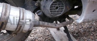
Generator maintenance mainly comes down to tightening the threaded fasteners of the generator stator and rotor, as well as the wire terminals.
In order to remove the generator, you must:
- disconnect the wires of the ignition circuit, sensor, brake light and direction indicators from the generator terminals;
- unscrew the three screws securing the stator to the crankcase and remove the stator;
- Unscrew the bolt securing the generator rotor and, with light, careful blows of a wooden hammer on opposite sides of the rotor, remove it from the trunnion and remove the key.
Ignition adjustment Voskhod
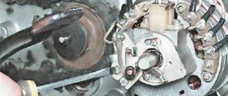
The ignition timing is set by turning the generator stator after first loosening the three screws securing the stator to the crankcase. For normal engine operation, it is necessary that the moment of spark formation (on the generator, this moment is determined by the coincidence of the sensor rotor groove with the protrusion on the sensor coil frame. Fig.) coincides with the moment when the piston does not reach the top dead center of 2.5-3.0 mm (at running the engine on gasoline with an octane rating of 92).
The gap between the rotor and the core of the sensor coil should be within 0.3±0.05mm.
The gap should be set as follows:
- loosen the screws securing the sensor stator to the generator stator cover;
- By moving the sensor stator in the grooves of the generator stator cover, set the required gap, and then tighten the fastening screws.
For more accurate ignition installation, it is recommended to determine the piston position with the cylinder head removed.
IS IT POSSIBLE TO INSTALL A CONTACTLESS IGNITION SYSTEM ON OLD MODELS OF KOVROV MOTORCYCLES?
The landing dimensions and dimensions allow this to be done. However, the electrical circuit needs to be modified: connect the KET or BCS. Increased spark energy will require another reel - B-300 B, interchangeable in terms of landing dimensions with the previously used B-300.
Externally, the old and new reels are no different. However, numerous attempts not to change the old unit sooner or later ended with the windings burning out. Those who like to improve the performance of power systems can be advised to install a bobbin from IZH (7.109-37.05.010). Its use increases the duration of the spark pulse by approximately 15% and its energy by 60%. As a result, starting the engine is noticeably easier.
IS IT POSSIBLE TO CONVERT THE “VOSKHOD-2” MOTORCYCLE WITH ELECTRONIC IGNITION SYSTEM DEVICES WITHOUT REPLACING THE ENGINE?
Such a change is possible. To do this, instead of the G-421 generator, it is necessary to mount a G-427 on Voskhod-2. It should be borne in mind that to fasten the rotor of the G-427 generator, a bolt with an M7x1 thread 85 mm long is required, that is, 10 mm longer. After installing electronic system devices on the motorcycle, it is necessary to adjust the ignition timing - it is 2.5-3 mm for the piston. m.t. The moment of sparking corresponds to the coincidence of the groove of the sensor rotor, available on the G-427 generator, with the protrusion on the frame of the sensor coil (Fig. 5.23), while the gap between the coil core and the sensor magnet must be set within 0.3 ± 0, 05 mm.
To do this, first loosen the screws tilting the sensor stator in the grooves of the cover, set the required gap, and then tighten the fastening screws. It is somewhat more difficult to install the Voskhod-2M engine or electronic ignition system devices on the Voskhod and Kovrovets motorcycles. There, in addition to the work listed above, you will have to mount a central switch. To do this, it is necessary to make a hole with a diameter of 27 mm in the headlight housing on the left side (Fig. 5.24) in order to secure the central switch in it.
You can also replace the FG-138 headlight with an FG-133, and drill holes in the left casing of the front shock absorber to access the switch (Fig. 5.25).
The connection diagram for electrical components to the central switch is shown in Fig. 5.26. If your motorcycle is not equipped with turn signals, the coil of the G-427 generator, which operates on their circuit, remains unloaded.
THE ENGINE OF THE MOTORCYCLE “VOSKHOD-3” WITH ELECTRONIC IGNITION CONTINUES TO WORK AFTER IT IS SHUT DOWN. SWITCH IS OK. WHERE TO LOOK FOR THE REASON?
As practice shows, most often the reason lies in the sensor circuit. If the wire in terminal (4) of the ignition switch becomes loose, then in the “Off” position the sensor does not close to “Ground”.
ON THE MOTORCYCLE “VOSKHOD” WITH GENERATOR G-427, THE ANCHOR OF THE INDUCTIONAL CONTACTLESS SENSOR FRONTED. CAN IT BE REPAIRED?
When such a malfunction occurs, the ignition timing first becomes unstable, and then the armature can become so loose that the rotor protrusion hits it. As a result of such an impact, the sensor is significantly damaged.
If the sensor winding is damaged, it will have to be replaced with a new one.
If the winding is not damaged, then the sensor can be repaired.
To do this, you need to use pliers to return the armature to its original position and, having thoroughly degreased the adjacent surfaces, glue the armature to the sensor base plate and the coil with epoxy resin. After the resin has hardened, the damaged surface of the armature must be carefully processed with a file so that its surface becomes parallel to the component surface of the rotor. If you put the resin in a thick layer, then its excess must be removed so that it does not interfere with adjusting the gap between the rotor and the sensor. It is best to glue the anchor immediately on the new engine, without waiting for its failure, which, as usual, happens at the most inopportune moment.
THE MODERN IGNITION SYSTEM OF KOVROV MOTORCYCLES IS QUITE RELIABLE, BUT SOMETIMES IT FAILS. HOW TO CHECK AND ELIMINATE IGNITION FAULTS IN “OWL” AND “PILOT” MOTORCYCLES?
Before starting repairs, you should check for breakdown of the spark without a spark plug cap. Set a gap of 6-7 mm between the high-voltage wire and the cylinder head ground. If there is no spark. start searching for it more methodically. You probably did not connect the plug connectors tightly. Poor contact of the base of the BCS housing with the “ground” does not have any effect on the operation of the system - the “ground” is output by a separate wire. But in old KETs, the “mass” was brought out to the body, and its contact with the frame is necessary.
The generator itself rarely fails. To check its performance, you need a tester with an ohmmeter function. Thus, the resistance of the charging windings (red wire and housing, or terminals “3” and “M”) should be within 400 Ohms: the resistance of the sensor windings (black and disposable wire, or terminals “D” and “M”) - 40 Ohms , The winding resistance of the lighting circuit (purple wire and housing) should be 0.4 Ohm.
All resistance measurements are made on the sockets of the generator harness plug block disconnected from the BCS. Old generators with KETs are checked in the same way. Instead of resistance, you can measure the magnitude of AC voltage. On the charging windings, when cranking the crankshaft with the kickstarter, it is approximately 50 V, on the sensor windings - about 2 V. The specific voltage value depends on how sharply the kickstarter lever is pressed.
The rotors of Kovrov motorcycles are an eternal part. The bobbin (high-voltage transformer 2102.3705, 1480026900001) is checked using an ohmmeter with the wires disconnected. The resistance of the primary circuit should be within 0.4 Ohms, the secondary circuit - 6.7 kOhms.
But even if the winding resistance is normal, and a spark jumps when you press the kickstarter, the unit may still be faulty. It happens that the motorcycle starts, but when the speed increases, interruptions begin and the engine stalls. This is a consequence of broken contact inside the housing. Therefore, the only reliable diagnostic method should be replacement with a known good part. Ideally, you should carry with you a high-voltage wire with a cap and a reel in the BCS. By connecting these nodes in series, the fault can be quickly identified.
Unfortunately, neither the reel nor the commutator can be repaired, since they have non-separable housings.
AT VOSKHOD-3 THE KET-1A SWITCH FAILED. IS IT POSSIBLE TO REPLACE IT WITH DEVICES OF TYPE 38A.3734 OR “TANDEM-3”?
It is forbidden. Both of these switches are designed for DC electrical equipment systems with a battery, and will not work on Voskhod.
ON THE OLD “SUNRISE” A NEW “3M-01” ENGINE WITH A 90-WATT GENERATOR IS INSTALLED. A NEW SWITCH BKS-70.3701 WAS ALSO INSTALLED. AFTER THIS UPGRADE, PROBLEMS AROSE WITH STARTING THE ENGINE. THERE IS STRONG KICKBACK IN THE KICKSTARTER LEVER, ADJUSTING THE IGNITION DOES NOT HELP. WHAT IS THE REASON FOR THE STRONG RECOIL?
The main reason is that the switch does not match the type of generator; a 90-watt generator will work normally with switches like 80.3701 or 2MK308. They differ from the 70.3701 switch by the presence of a special filter in the ignition circuit. In your case, when these blocks are incompatible, wandering ignition timing inevitably occurs. This explains the strong impact of the kickstarter.
IS IT POSSIBLE TO INSTALL A BATTERY ON THE OWL MOTORCYCLE? WHAT WILL HAVE TO BE DONE IN THIS CASE?
The battery can be installed on the “Owl” motorcycle, as well as on the “Courier” and “Farmer”. Minor modifications will be required.
First, modify the standard ignition switch (192005490201). Unscrew the two screws in the housing, remove the locking mechanism (“cylinder”) with the spring-loaded contact strip. At the base of the lock, at right angles to the existing standard ones, drill two holes for contacts. Now, when the key is turned and the position is "on", the contact strip should close the two additional contacts.
Connect one of the new contacts through the DR-100 choke (used on Voskhod-2M) to terminal “01” of the BKS-1MK-211. Connect the second terminal of the lock through a fuse to the positive terminal of any 12-volt motorcycle battery. (As a last resort, you can limit yourself to cheaper 9- or 12-amp-hour batteries that are not designed for high starting current). Naturally, connect the battery negative to ground. All that remains is to find a place and secure the battery.
In order to ensure the passage of large currents through the circuit when the headlight is on, two diodes (VD1 and VD2) must be connected to the circuit, as shown in Fig. 5.28. You can use any parts of type D205 that allow a current of 8 A.
To convert all lighting devices to direct current, disconnect the wire from terminal “02” in the connector and connect it to terminal “01”. We also recommend replacing the car horn and turn signal relays with car horns. They will work more efficiently in this circuit.
IS IT POSSIBLE TO INSTALL AN IGNITION COIL FROM A JAVA MOTORCYCLE ON THE OWL?
Any "Owl" and any "Voskhod" work perfectly with an ignition coil from a "Java". The polarity of the connection in this case does not matter.
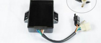
Switch Voskhod – electronic KET-1
The electronic switch KET-1 is designed to work in the ignition system complete with the G-427 generator and the B-300B high-voltage transformer. Allows you to obtain a secondary voltage of up to 18 kV, at a generator rotor speed of 250 to 7500 rpm. The switch is installed in the right toolbox. The base of the commutator is connected to the ground of the motorcycle. If the switch fails, it can be disassembled and repaired
The electronic switch has three output terminals with letter markings on the body >, > and >. The ground terminal is the base of the switch.
Maintaining the switch during operation comes down mainly to tightening the threaded connections, while avoiding stripping the threads. It is necessary to protect the switch from moisture getting inside it and onto the terminals from sudden shocks and exposure to high temperatures. You should also systematically check the reliability of the electrical connection of the switch base with >, because If this condition is violated, sparking on the spark plug stops.
Motorcycle Voskhod-3M: technical and external characteristics, pros and cons, tuning options
It is no coincidence that the Soviet road motorcycle Voskhod-ZM is still remembered and appreciated by domestic motorcyclists. Soviet teenagers witnessed his high popularity. The light weight of the motorcycle allows it to withstand a load of 160 kg. Despite its decent quality and reliable safety system, it was discontinued in 1993.
Spark plug Voskhod - spark ignition type A-23
During operation, the spark plug must be periodically cleaned of carbon deposits and the gap between the electrodes must be adjusted, which should be within 0.6-0.7 mm, which is ensured by bending the outer electrode. To seal, a copper-asbestos gasket is placed between the spark plug and the cylinder head. To eliminate radio interference created by the ignition system, a shielded tip of type A-4 is placed on the spark plug.
REPAIR OF MOTORCYCLE IGNITION SWITCHES
More than two years have passed since I installed contactless ignition on my Izh-Jupiter 4 motorcycle based on a Voskhod generator, switch 262 3734 and a homemade diode mixer (Fig. 1.).
Having convinced myself of the reliable operation of my creation, my colleagues decided to make a similar improvement to their motorcycle equipment. However, questions like “I assembled it according to your scheme - explain why it doesn’t work for me” arose. Here are some typical faults:
— no spark at all;
— the engine works well at idle, but fails at speeds above average;
- the engine starts well, but mainly one cylinder works, the second one picks up occasionally, the flashes follow unevenly,
- there is no spark only when installed in the Izha circuit - on Voskhod there is a spark, when replacing the switch-stabilizer unit (BKS) with a similar one of a different type (251 3734 on KET 1-A), the fault disappears.
All of the above troubles indicate a defect in the BCS. Let's look at the factory diagram of the block (Fig. 2.). It is copied from the KET 1-A block produced in the 1980s. In terms of switches, the VD2 zener diode is represented by KS650 (or two D817B connected in series). The latest versions of BKS - 251 3734, 261 3734, 262 3734 are not schematically different. Only the appearance and type of some parts have changed.
Rice. 1. Non-contact ignition based on a Voskhod generator, switch 262.3734 and a homemade diode mixer
Rice. 2. Schematic diagram of a factory-produced switch-stabilizer (BKS) unit
Rice. 3. Scheme for checking capacitors and thyristors for leaks
Rice. 4. Diagram of the device for selecting thyristors VS1
The operating principle of the devices is the same: capacitor C2 is charged from the high-voltage winding of the generator along the circuit VD1, C1, VD2, VD4, R2. With a positive voltage pulse from the transmitter, the thyristor VS1 opens through VD3, which discharges C2 onto the winding of the ignition coil TV1, forming a spark on the spark plug F1. Zener diode VD2 limits the voltage on C2VS1 at 130 - 160 V. However, on a working switch, the voltmeter showed 194 V - an obvious overvoltage, the influence of the spread in the parameters of the zener diode. I would like to note an interesting detail - two MBM type capacitors were used as C2. Such capacitors can operate in pulse mode for a long time. Being “self-healing”, they easily tolerate short-term overvoltages. The breakdown areas of the plates are filled with paraffin impregnation of the dielectric. Unfortunately, this does not go away without leaving a trace - over time, the foil coverings begin to resemble a sieve, and the capacity of the device decreases. Dielectric breakdowns lead to an increase in conductivity and the appearance of leaks. When working in a switch, such a capacitor simply does not have time to accumulate charge during the time between two sensor pulses. This is why the unit that works normally on Voskhod (Minsk) malfunctions in the Izha circuit, where the frequency of the trigger pulses is twice as high.
A leaky capacitor is identified using a simple diagram (Fig. 3). In compliance with safety measures (the circuit is galvanically connected to the household network), we connect the capacitor being tested into the circuit. The indicator lamp should not light up - the glow indicates the presence of a leak. Check time is 15 - 30 minutes (in doubtful cases - up to 1 hour). Despite the somewhat barbaric method of testing, it is practically safe for the capacitor. During operation, it is subjected to heavy loads. Thus, I identified thirteen capacitors with obvious leaks, four of them in blocks that worked normally on single-cylinder engines, but failed in the Izha circuit. Replacing capacitors in KET-1A is not difficult - the unit can be easily disassembled. The same replacement in version 252.3734 is more difficult. First, remove the porous mass filling the housing by boiling the switch in boiling water for 15 - 20 minutes. Then we carefully pluck out the filler with tweezers. By pulling the connectors, we remove the board and gain access to the printed circuit board. You can, of course, replace a faulty device with a similar one, but there is no guarantee that the new one will not fail soon either (see the reason above), so I recommend replacing it with capacitors like K73-17 1.0 μF/ 400 V (or even better, 4x0.47 μF/ 630V). Two capacitors are normally located on the board. We seal the block by filling it with construction foam or a rubber plate cut to size. I would warn you against using various auto sealants - their active components will eventually destroy the copper traces of the board. In order to ensure maximum reliability of the device, I consider metal-paper capacitors of the MBG, MBGP, MBGCh types (the letter G indicates the design of the device), designed for a voltage of 400 - 630 V, as a “no alternative” option. The only problem in this case is the dimensions. A compromise option in the circuit for “Izh-Yu” is possible: we reduce the value of C2 to 1 μF. This will ensure its guaranteed charge in half a revolution of the crankshaft.
The remaining elements of the device usually do not cause any particular complaints. S1 (K73-15) is quite reliable. I advise you to replace diodes VD1, VD4 with KD226G (with a yellow ring) VD3 is practically “indestructible”. It happens that the VS1 thyristor changes its characteristics (the engine starts to start in the opposite direction) - this can be eliminated by replacing it with a KU202N or (even better) with a T122-20-10. It is extremely rare for KU221G (KU240A1) to fail. Replacing the SCR involves selecting the minimum control current. This ignition circuit is very demanding on this parameter. I carry out the selection using the circuit shown in Figure 4. Moving the R1 slider from bottom to top, we use the milliammeter PA1 to note the opening current of the test SCR VS1 at the beginning of the glow of the EL1 lamp. For use, we select specimens with a control current I = 1 - 8mA. Unfortunately, there are SCRs with increased leakage current. This parameter is checked according to the diagram shown in Figure 3. The glow of the lamp will indicate a malfunction of the device.
The BKS restored in this way is suitable for further use in the ignition system of both single- and two-cylinder motorcycles.
D. RASKAZOV, Kashira
We recommend reading
- GAZ-AA - GAZ-MM GAZ-AA: FROM DIP TRUCK TO BUS. Family of cars GAZ-AA - GAZ-MM. The need for a mass-produced one and a half ton car arose in the Soviet Union in the late 1920s - in...
- Panel fencing Panel fencing is one of the popular types of fencing used in many areas. Today, panels of metal rods are used, connected to each other by welding....
Ignition switch Voskhod - central switch
Switch 124005490201 is used as a central software switch that provides the necessary switching of lighting equipment on a motorcycle. The switch has three operating positions >, >, > in accordance with the following operating modes:
- in position > – the generator sensor circuit is shorted to ground, which ensures the engine stops.
- in position > (driving during the day) – the ignition circuit is turned on, the direction indicator circuit operates (when the direction indicator switch is on) and the brake signal circuit (when the brake pedal is pressed);
- in position > (driving at night), two circuits are switched on:
- a) a circuit of speedometer backlight lamps, license plate lighting and city driving (through a throttle, which serves as a device that complements the parametric control of the generator);
- b) headlight lamp circuit A6-32+32 (via the light switch on the steering wheel).
Caring for the central switch comes down to periodically checking the reliability of the switch in the headlight and cleaning the moving and fixed contacts from dust and dirt by washing them in gasoline.
Switch P-200
Light switch with horn button (located on the left side of the steering wheel). To switch the low and high beam circuit, a P-200 type switch is used with a built-in push-button horn switch for three operating positions: neutral - the headlight lamp is off; far right – low beam is on; far left – high beam is on.
The horn button has a movable contact connected to ground and a fixed contact connected to one of the wires coming from the horn terminal. When you press the button, the contacts close and the signal circuit is completed.
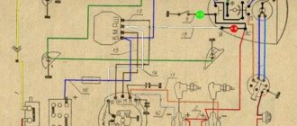
Electrical circuit of the Voskhod motorcycle
Central switch. 2. speedometer. 3. Speedometer light. 4. Headlight. 5. Headlight lamp. 6. City driving lamp. 7. Sound signal. 8. Direction indicator lamp. 9. Direction indicators. 10. Direction indicator switch. 11. Electronic switch. (D – sensor terminal, K – ignition coil terminal, G – generator terminal.) 12. Throttle. 13. Relay breaker. 14. Generator. 15. License plate lamp. 16. Brake signal lamp. 17. Rear light. 18. Wire connection block. 19. Brake light switch. 20. Shielded spark plug cap. 21. Spark plug. 22. High voltage wire. 23. Ignition coil. 24. Light switch.
Wire colors: sn. – blue, cf. – grey, g. – blue, g. – yellow, h. – green, k. – red, kor. – brown, op. – orange, f. – violet, h. – black.