IZH hydraulic brake: description
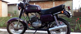
IZH PLANET 5, IZH JUPITER 5-01
In the domestic motorcycle industry, serial production and equipping of motorcycles with disc brakes began with the IZH Planet 5 motorcycle in configuration 015. The use of disc brakes made it possible to obtain high stability of the braking characteristics of the motorcycle as a whole and a significant reduction in labor intensity during operation.
The hydraulic disc brake consists of a master cylinder located on the right side of the handlebar, a brake caliper attached to the left front suspension movable tube, a hydraulic hose connecting the master cylinder to the brake caliper, and a brake rotor mounted with six bolts on the left side of the front wheel.
The brake master cylinder, mounted on the right side of the motorcycle handlebar using a bracket with two screws, consists of a cylinder body, in the upper part of which there is a reservoir for brake fluid, closed with a lid. The cover is secured with screws. The seal between the body and the cover is made by a diaphragm. In addition, the diaphragm acts as a buffer and serves to equalize the pressure that changes in the master cylinder reservoir when the piston with cuffs moves. The level of brake fluid in the reservoir is monitored through a level indicator installed in the cylinder body through an o-ring. At the bottom of the cylinder body there is a piston unit connected to the reservoir through two holes. The piston assembly consists of a piston with cuffs and fixed in the main cylinder body using a retaining ring and a valve closed with a protective cover, a return spring and a thrust washer. The movement of the piston assembly and, therefore, the operation of the entire main cylinder is controlled by a double-arm drive lever.
To signal that the front brake is engaged, a switch is installed in the master cylinder housing.
When the driver presses the drive lever, the lever, turning, releases the contact of the switch and, thus, sends a signal to the rear light to turn on the front brake, and the force begins to be transmitted through the double-arm lever and the heel to the piston. The piston, moving, closes the connection with the master cylinder reservoir with a cuff and begins to compress the fluid, which is located in the space above the piston, and move it through the outlet hole into the brake hose. In the brake hose, depending on the force applied to the lever, pressure arises, which is transmitted to the brake caliper. The piston returns to its original position by means of a return spring, and the liquid flows through the valve. The main working element of the master cylinder is the main cuff, with the help of which pressure is created in the system and the performance of the entire system depends on the condition of which.
The next element of the brake system is the brake hydraulic hose, which connects the brake master cylinder to the brake caliper. The brake hose consists of a hose, two ends, which, using special bolts and sealing washers, connect the hose to the brake master cylinder and brake caliper. The upper connection, i.e. the connection between the brake hose and the brake master cylinder, is covered with a protective cover.
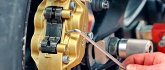
The front brake caliper consists of a shoe guide, a guide pin, a caliper body, a brake pad, a latch, a piston with an O-ring and a piston boot with a retaining ring, and an air release valve with a protective cap. This design of the front brake caliper is called “floating”, since the pad guide is rigidly attached with bolts to the left movable pipe of the front suspension, and the caliper itself, relative to the guide, moves along the guide pin with a protective cover. Thus, the brake caliper, together with the “floating” brake pads, selects a position that ensures a uniform minimum gap between the brake pads and the brake disc, both to the left and to the right of the brake disc. When you press the handbrake lever, pressure is applied through the brake hose to the caliper between the piston and the caliper body, causing the piston to move and transmit force to the brake pad. The piston moves within the elastic deformation of the sealing ring. The pads move closer together and clamp the brake disc together. The clamping force of the brake disc depends on the force applied to the handbrake lever. The return of the pads to their original position and the establishment of the required gap after removing the forces on the handbrake lever occurs due to the elastic properties of the rubber from which the o-ring is made. This floating caliper design with a moving piston allows you to always have the same clearance between the brake pads and the brake disc. When the brake pads are worn (their condition can be monitored through the indicator cover), the gap between the brake disc and the pads is automatically maintained within the required limits due to the movement (slipping) of the piston relative to the sealing ring when force is applied to the handbrake lever.
During the assembly process, the entire system is filled with 200 g of Tom brake fluid and pumped to remove air pockets and bubbles from the system.
During operation, it is necessary to monitor the presence of brake fluid in the system. Control is carried out through a level indicator located on the brake master cylinder. Brake fluid monitoring must be carried out before each departure, for which the motorcycle is placed on a central stand on a horizontal section of the road, the steering wheel must be in the straight driving position, and the brake fluid level in the brake master cylinder must be slightly higher than the average diameter of the fluid level indicator. If this level is lower, it is necessary to add brake fluid. To do this, you need to unscrew two screws, remove the cover and diaphragm, add fluid to the required level and reassemble in the reverse order.
It is also necessary to ensure that fluid does not leak from the entire hydraulic drive system. In the event of a leak, it is necessary to determine the location of the leak and eliminate it. If there is a leak in the places where the hydraulic hoses are attached to the cylinder or bracket, the connection must be tightened. A leak is also possible due to excessive wear of the seals in the brake master cylinder or due to failure of the seal in the brake caliper. In both cases, the leak is eliminated by replacing parts. To replace the cuffs in the brake master cylinder, you need to remove the lever, take out the protective cover, use a special tool in the form of tweezers or sharpened scissors to remove the retaining ring and then remove the piston with the cuffs. Replace the worn cuff with a new one and reassemble in the reverse order. If there is a leak through the brake caliper seal, which is very rare, it is necessary to remove the caliper from the motorcycle, remove the brake pads from it, carefully remove the protective boot, remove the piston and O-ring. Replace worn parts and reassemble in reverse order. In all cases, after replacing brake system parts and assembling, the system must be filled with fluid and pumped.
Brake pad wear should be monitored. The thickness of the asbestos mass molded to the block reinforcement is 7 mm. During operation, it is allowed to reduce the thickness of the asbestos mass to 1 mm, after which the brake pads must be replaced. To change the pads, you need to unscrew the bolt securing the bracket to the guide and rotate the bracket, moving it out of the brake disc area. Remove the brake pads, replace them with new ones, carefully push the piston inside the caliper using a mounting blade and reassemble.
In an adjusted and working hydraulic disc brake, when pressing the handbrake lever after selecting free play (15...25 mm), the driver should feel a hard stop. The absence of such a stop (the feeling of the lever “sinking”) indicates a malfunction in the system. The reason for the failure of the lever may be the presence of air in the hydraulic system (the system is not pumped) or excessive wear of the main cuff in the master cylinder of the brake.
Bleeding the system is performed in the following order:
— fill the reservoir of the brake master cylinder with fluid to the recommended level (the filling procedure was given above);
— clean the air release valve on the brake caliper from dust and dirt and remove the rubber protective cap from the riveting head;
— place a rubber hose on the valve head, immerse the free end of the hose in brake fluid poured into a clean glass container with a capacity of at least 0.5 liters, filled to half its height;
- sharply press the hand brake lever with your hand sequentially 3 ... 4 times with an interval between pressing 1 ... 2 s, and then, leaving the lever pressed, unscrew the air release valve by 1/2 ... 3/4 of a turn, while in the flowing liquid will appear air bubbles;
— after liquid has stopped flowing out of the hose, screw the air release valve all the way;
- repeat the last two operations until the release of air bubbles completely stops.
When removing air from the hydraulic drive system, constantly monitor the brake fluid level in the master cylinder reservoir and do not allow the level to drop more than 2/3 of the normal value.
After the air release from the hose has completely stopped, keep the handbrake lever pressed, screw the air release valve as far as it will go and only then remove the hose from its head. Next, put a protective cap on the valve head and add liquid to the normal level.
ATTENTION! The brake fluid released into the vessel when pumping the system can be reused for refueling only after it has settled (at least 24 hours) until the air contained in it has been completely removed and has been filtered.
TECHNICAL CHARACTERISTICS OF HYDRAULIC DRIVE OF FRONT WHEEL DISC BRAKE
| Master cylinder diameter, mm | 15,8 |
| Piston stroke, mm | 16 |
| Working cylinder diameter, mm | 38,1 |
| Friction lining dimensions: | |
| width, mm | 35 |
| thickness, mm | 7,0 |
| total area, cm2 | 38 |
| Brake disc dimensions, mm: | |
| thickness | 5 |
| outer diameter | 298 |
| Effective friction radius, mm | 133,5 |
| Brake fluid volume, l | 0.2 |
| 1. Drive lever 2. Level indicator 3. Master cylinder cover 4. Hose 5. Bracket 6. Cylinder body 7. Plate 8. Cover 9. Diaphragm 10. Screw 11. Protective cover 12. Retaining ring 13. Cuff 14. Piston 15 Valve 16. Main cuff 17. Thrust washer 18. Spring 19. Shoe guide 20. Latch 21. Brake pad 22. Anti-squeak plate 23. Piston boot 24. O-ring 25. Piston 26. Brace body 27. Bolt 28. Protective cover 29. Guide pin 30. Air release valve (cap) 31. Indicator cover 32. Bolt 33. Bushing 34. Bushing 35. Spring |
11 12
5.3.7.
Motorcycle brakes IZH 7.107-01
The motorcycle brake system consists of mechanisms installed on each wheel and two independent drives to control them.
The front wheel of the motorcycle can be equipped with a hydraulic disc brake or a two-cam drum brake.
The mechanical foot drive is used to brake the rear wheel of the motorcycle.
Maintenance of the front wheel disc brake of motorcycles IZH 7.107-01
The front wheel handbrake with hydraulic drive does not require adjustment.
Inspection of the brake pads is carried out without removing the wheel, through the oval window of the bracket with a rubber cover. The pads must be replaced when the friction linings wear down to a thickness of 1 mm. To replace the brake pads, unscrew the locknut of the brake caliper housing bolt, unscrew the bolt from the pad guide, and turn the brake caliper housing counterclockwise on the guide pin, thereby freeing access to the brake pads. Remove the worn pads from the pad guide and install new ones. Pay attention to the correct fastening of the pads with two spring latches. Attach an anti-squeak plate to the movable brake pad; the direction of the arrow on the plate should coincide with the direction of rotation of the wheel.
Rice. 25. Hydraulic brake drive:
1 — “stop” switch; 2 — cover; 3 - hose; 4 - bolt; 5 - cover; 6 - screw; 7 - axis; 8 — body; 9 — lever; 10 - lock nut; 11 — adjusting screw
Assemble the brake in the following order: move the piston inside the caliper housing, rotate the housing to its original position on the guide pin, secure the housing to the pad guide with a bolt and lock nut.
When removing the brake disc, it is necessary to make a mark on the disc and wheel hub. Install according to the marks.
Replacing brake fluid in the hydraulic drive of the front wheel brake
Brake fluid is used to fill the hydraulic drive of the front wheel (Table 2). To change the fluid:
- Unscrew screws 6, remove cover 5 (Fig. 25) of the main brake cylinder and the diaphragm;
- remove the cap from the air release valve 1 (Fig. 26), put a rubber tube on the valve head, lower the second end of it into the drain container and unscrew the valve 1...1.5 turns;
- pressing lever 9 (Fig. 25) of the front wheel brake, drain the fluid from the system, adding fresh brake fluid to the main brake cylinder until the fluid is replaced in the entire system, make sure that the fluid is not completely removed from the main brake cylinder ;
- When fresh fluid flows out of the rubber tube, stop removing fluid by tightening the air release valve.
Figure 26. Replacing brake fluid:
1 - air release valve
If air gets into the hydraulic system and to control the brake system after replacing the brake fluid, it is necessary to bleed it (bleed air). For this:
- immerse the end of the rubber tube placed on the air release valve into a container filled with brake fluid;
- press sharply 3...4 times on lever 9 (Fig. 25) of the front wheel brake and, holding the brake lever pressed, unscrew the air release valve 1/4 turn for 1...2 s so that air comes out of the brake system (bubbles in the container) . Repeat this operation until air is completely removed from the hydraulic system;
- While holding the brake lever depressed, screw the air release valve all the way in and put on the cap;
- Fill the main brake cylinder with brake fluid to a level of up to 2/3 of the height of the inspection window;
- install the diaphragm, cover, tighten the screws;
- If it is difficult to bleed the brake system, check the reliability of the connections in the hoses and, if necessary, tighten the connections.
Adjusting the rear wheel brake of motorcycles IZH 7.107-01
Install the rear wheel brake lever 3 (Fig. 9) so that in the uppermost position it rests on the driver’s footrest roller 4, and use the adjusting screw (Fig. 27) located in the sprocket housing to ensure free travel of the brake lever pedal down by 5... 15 mm.
Rice. 27. Adjusting the rear wheel brake
Adjustment of a two-cam drum brake of motorcycles IZH 7.107-01
Make adjustments in the following order:
- Unscrew and remove the pin from the connection of the rod with the left short lever. Using adjusting screw 5 (Fig. 23), when unscrewed, the gap between the shoes and the brake drum decreases, adjust the tension of the brake cable so that when the wheel rotates, the lower block touches the brake drum, then tighten the adjusting screw 1/2 turn;
- by turning the left lever clockwise, bring the upper block until it touches the brake drum of the wheel and adjust rod 2 so that the gap between the block and the brake drum is minimal and ensures rotation of the wheel without touching the block. If the holes do not match, adjust the length of the rod by loosening the lock nut. Insert a finger into the hole of the left lever and rod and secure with a cotter pin;
- set a free play of 10...20 mm at the end of the front wheel brake lever. Do not allow the brake pads to touch the drum. The degree of wear of the brake pads is determined by the position of flag 4 (Fig. 23). The maximum permissible wear corresponds to the coincidence of the flag with the mark “1” on the brake drum cover when the hand brake lever is depressed. When assembling, set the flag to the “0” mark (the brake lever is not connected to the cable). After adjusting the brake, the flag will take a position between the “0” and “1” marks.
To improve the operation of the front wheel brake drive in the spring and autumn, we recommend lubricating the front brake cable cable with motor oil or brake fluid, and placing the adjusting screws with the groove down. Lubrication is done by dipping the rope into a container with oil and then moving the sheath (5-10 times) along the rope.
5.3.8. Rear wheel drive chain for motorcycles IZH 7.107-01
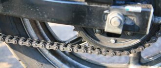
Rice. 28. Installing the chain lock latch, checking the chain tension
To apply lubricant to the chain, disconnect the lock, remove the chain, wash and apply lubricant (see Table 2) or remove the right crankcase cover and, turning the rear wheel, apply lubricant to the chain. When assembling the chain, connect the links with a lock, install the latch with the cut in the direction opposite to the movement of the chain (Fig. 28).
Check the chain tension by pressing the lower rubber cover of the chain up and down in the middle of the cover (Fig. 28). When moving the chain more than 30 mm, tighten it by changing the position of the rear wheel axis with nut 3 (Fig. 29). After adjusting the chain, tighten the nuts of the axle shaft, axle and braces. If the chain is too long, shorten it by two links using the connecting link and the tool included in the kit. When adjusting the chain, make sure that the wheels are in the same plane. Adjust the alignment of the wheels in one plane using the marks on the pendulum fork and the protrusions of the chain extensions. After adjusting the chain tension, be sure to adjust the rear wheel brake.
Rice. 29. Chain tension adjustment:
1, 2, 3 — nuts; 4 - lock nut
5.3.9. Motorcycle speedometer gearbox IZH 7.107-01
Maintenance of the speedometer gearbox involves lubricating the gears. To do this, remove the disc brake housing, unscrew the bolt, remove the flexible shaft and gear bushing. Wash and lubricate parts. Reassemble in reverse order.
content .. 10
11 12