Extreme.Newline.by
Motorcycle engines have either constant or variable ignition timing . With constant ignition timing , the beginning of the breaker break, and, consequently, the appearance of a spark, remains unchanged in all engine operating modes. With variable ignition timing, the moment of spark appearance is changed manually or automatically - with a centrifugal regulator, which, as the speed increases, increases the ignition timing from 10 to 30°. (see continuation)
In domestically produced motorcycles, the ignition timing according to factory data:
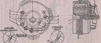
For two-cylinder engines M-61 and K-750, the breaker cam is a continuation of the camshaft, so the ignition timing is set at the factory. These machines have the same hammer break value for the right and left cylinders.
- - hole for decompressor;
- - rod for determining c. m.t.;
- — fixed contact of the breaker;
- — breaker lever;
- - fist.
The procedure for adjusting the ignition of a Java 350
Remove the right engine crankcase cover. Remove the spark plug and replace it with a device for determining the position of the piston. Turning the crankshaft with a wrench S=10 mm, placed on the head of the cam mounting bolt, place the piston in the idle position.
Set a gap between the contacts equal to 0.3 - 0.4 mm, to do this, loosen the screw securing the anvil and turn it around its axis in the desired direction. After tightening the screw, check the gap - a 0.3 mm thick feeler gauge should go through easily , but a 0.4 mm thick feeler gauge should not go through .
Connect the test lamp with one wire to the terminal clamp of the hammer, and the other to any ground point of the motorcycle. Turn on the ignition , and the lamp connected in parallel to the breaker contacts should light up.
Turning the crankshaft counterclockwise, lower the piston by the amount of ignition timing specified in the instructions. Count down according to the device. At the moment when the piston takes the desired position, the lamp should go out, signaling the closure of the contacts. If the contacts close earlier (the lamp goes out), it means the ignition is later , and later the ignition is early. In both cases, slightly loosen the screws securing the breaker disk and lightly hit the bent stop 12 (using a screwdriver) and turn it clockwise if the ignition is early, and counterclockwise if it is late. Tighten the base mounting screws and check the ignition installation. To do this, lower the piston 5 - 7 mm (the lamp does not light - the contacts are closed) and slowly raise it again. The lamp should light up (the contacts will open) at the moment when the piston does not reach TDC. by the amount of ignition timing (see TABLE ABOVE). Turn the crankshaft several times using the kick starter, and then check the ignition timing again when the piston moves to the top dead center. It should be remembered that when performing this work, you cannot keep the ignition on for a long time, so as not to damage the ignition coil.
On the Java-350 the ignition timing is adjusted in a similar way, first for the right cylinder - accordingly, the upper breaker, then for the left - the lower breaker. To do this, loosen the fastenings of the base (disk), and then for the left cylinder - the fastenings of the sector. To ensure synchronous engine operation, the ignition in both cylinders should be set to the same.
It sometimes happens that the required ignition timing of the JAVA 350 cannot be set due to the insufficient length of the groove limiting the rotation of the base. This indicates excessive wear on the breaker hammer stop or chipping. In this case, you need to replace the stop or install a new hammer.
During operation, the heel of the breaker hammer wears out and its height decreases. The anvil and hammer with contacts less than 0.5 mm thick are replaced with new ones. The wear occurs especially intensively after installing a new hammer. Changing the height of the heel of the hammer causes a change in the ignition timing.
Wear reduces the gap between the breaker contacts and the initial advance , and installing a new unused hammer to replace the failed one increases the gap between the breaker contacts and the ignition timing . Therefore, after replacing the breaker parts, it is necessary to adjust the ignition timing.
FUOZ Saruman
Control and adjustment of ignition timing of Java 634 and Java 638 motorcycles.
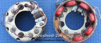
Rice.
1. Breaker Java 638 Monitoring and adjusting the ignition timing on the Java 350/638 motorcycle can be considered one of the main adjustment operations. Let us only recall that advance refers to a certain moment before the end of the compression stroke, at which the fuel mixture in the combustion chamber of the cylinder is ignited. Adjusting the ignition timing consists of two main operations, namely: setting the specified separation of both choppers located on the top of the generator, and adjusting the fuel ignition timing.
For this purpose, as a rule, gap checking probes are used, which are included in the standard equipment of the motorcycle, and a special measuring device from the service tool kit, which is alternately screwed into the holes for the spark plugs of the right and left cylinders. This measuring device is a cylindrical body (with a M14x1.25 thread at one end), through which a rod passes with marks along the circumference at a distance of 1 mm from each other. For more accurate measurements, you can also use a micrometer with a threaded end.
If you're tired of constantly adjusting your ignition, upgrade to Saruman's state-of-the-art electronic ignition system. It is easy to set up, produces a strong spark and ensures fast acceleration of your motorcycle. Go to FUZ Saruman
Procedure for monitoring and adjusting Java 634 and Java 638 motorcycles.
After removing the right engine crankcase cover, first check that the alternator stator mounting bolts and the cam center screw are properly tightened. If necessary, tighten them with a screwdriver and a 10mm spanner. Check the condition of the breaker contacts, and if necessary, trim their supporting surfaces with a file or sandpaper. If they are worn or burned, replace the rocker arms and contacts. The contacts in the closed state must be adjacent to each other with their entire surface. Unscrew the spark plugs and screw a special millimeter measuring device into the hole under the right spark plug. Do not extend the measuring device, but leave approximately 1 mm from the supporting surface, so that during subsequent measurements you can accurately determine the starting position. First, the ignition advance of the right cylinder is set by the upper chopper, and only then the ignition advance of the left cylinder is set by the lower chopper.
First you need to check and, if necessary, set the correct separation. The separation refers to the maximum distance between the fixed contact of the breaker and the contact of the breaker lever when the lever is raised as much as possible by the cam on the generator rotor. Place a flat or socket wrench of 10 on the central screw of the cam (see figure) and turn clockwise. The position in which the breaker lever is maximally raised by the cam must be noted on a millimeter measuring device. Its rod is in the highest position, which means that the piston of the right cylinder is at top dead center. The distance now between both contacts of the breaker represents its separation, which should be 0.3 mm. This size is checked with gap gauges. The motorcycle accessory kit contains a double dipstick consisting of two plates: 0.3 mm and 0.4 mm. The thin plate (0.3 mm) of the probe should pass between the breaker contacts, but the thicker plate should not pass. If the distance does not correspond to the specified value, use a screwdriver to loosen the fixing screw of the fixed contact holder. Then move the contact holder either towards or away from the breaker lever so as to adjust the separation to the desired value of 0.3 mm. Slightly tighten the screw of the breaker contact holder, and measure the adjusted separation size again with feeler gauges. If everything is in order, tighten the screw completely.
Rice. 2.Java 638 Interrupter
If the breaker lift is correctly adjusted, the ignition timing should be checked and, if necessary, adjusted. To do this, you need to check whether the piston of the right cylinder is still at top dead center. Then turn the cylindrical body of the measuring device so that the mark of the movable rod coincides with the control edge of the body. By turning the crank mechanism counterclockwise, reduce the piston position by the specified ignition timing value of 2.7 ± 0.2 mm before top dead center. The beginning of the separation should be in this position. This is the moment when the breaker contacts begin to move away from each other and there is a gap of about 0.05 mm between them. As you know, the fuel mixture in the cylinder is ignited just at the moment when the breaker contacts are disconnected. To determine the moment of separation, a strip of thin foil or cigarette paper is used, which is inserted between the contacts of the breaker. While turning the crank mechanism, as stated above, slightly move the foil between the contacts until you feel it being compressed by the contacts in the desired position. However, it should be noted that the correct torque may be distorted depending on how much force is applied to the strip of foil or paper, and therefore when it is considered compressed.
The angular rotation of the crank mechanism and thus the displacement of the piston can be quite large and thus the measurement can be distorted. Therefore, we recommend that to determine the exact moment of disconnecting or connecting the contacts of the breaker, use a regular 12 V electric light bulb (preferably 3 W), in a socket to which two wires with clamps at the ends are attached. One clamp is connected to the terminal of the breaker, the adjustable cylinder, and the other to ground (see figure).
If, with such a connection, the breaker contacts are open and if at the same time the key in the ignition switch is in the “ignition on” position, then the primary ignition circuit is open and the control lamp is on, because current can only flow through the newly connected circuit. The lamp goes out only at the moment we are looking for, when the breaker contacts are connected. If the lamp goes out or if the foil (or paper) is completely compressed between the contacts until the piston position decreases by 2.7 + 0.2 mm from top dead center, then the ignition timing should be increased. Conversely, it should be reduced if, after a given decrease in the piston position, the lamp continues to burn or the control foil passes freely. The ignition timing should be adjusted by turning the base plate of the breakers, slightly loosening the two mounting screws. When the plate is turned to the left, the advance increases and, conversely, when turning in the direction of rotation of the crank mechanism, the advance decreases. Having adjusted the distance between the contacts of the breaker, which corresponds to the moment the separation begins, use a screwdriver to tighten both fastening screws of the foundation slab. Then check the ignition timing again and correct it if necessary. The order of the cylinders mentioned above when adjusting the ignition timing should be observed due to the fact that as a result of installing the foundation plate, the ignition timing of the right cylinder is adjusted, and then on it, as a basis, the breaker plate of the left cylinder is shifted and adjusted. It follows from this that when adjusting the ignition timing of the left cylinder, the order of work is the same, however, with the only difference that it is not the foundation plate that should be turned, but only the lower breaker plate.
If you're tired of constantly adjusting your ignition, upgrade to Saruman's state-of-the-art electronic ignition system. It is easy to set up, produces a strong spark and ensures fast acceleration of your motorcycle. Go to FUZ Saruman
moto-fuoz.ru
Ignition adjustment Java 638
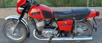
The Czechoslovak motorcycle has a number of advantages compared to other Soviet units, but is almost the same in terms of electrical equipment. The JAVA 638 wiring diagram is quite simple. Even an inexperienced motorist can handle repairs and maintenance.
Adjusting the ignition of the JAVA 638 is very important for the correct operation of the engine. You can do it yourself at home. To do this you need:
- Remove the spark plugs from both cylinders and remove the sump cover.
- After removing the spark plugs, install the indicator in the hole of the right cylinder.
- Now you need to fix the piston at top dead center. To do this, turn the crankshaft using a key.
- Then the cylinder contact spacing is adjusted. They should only touch slightly (distance approximately 0.35 millimeters ).
- A light bulb is connected to the contact on which the advance is set. This is done before setting up the ignition on the JAVE 638, to accurately measure the distances between the contacts.
- Zero is measured on the indicator, after which the position is fixed.
- The advance is different for each gasoline. So, when using the 92nd and 95th, the adjustment is 2.7-3.1 millimeters, for the 80th – 2.9-3.3 millimeters.
- If the installation is correct, the light goes out. Otherwise, adjustment will be carried out by a movable disk.
- An identical procedure is carried out on the other cylinder.
- When the adjustment is completed, crank the crankshaft several times using the kickstarter. Then the control ignition advance is performed. This completes the YAVA 638 ignition installation.
It is important to understand that if the ignition is incorrectly measured, the engine's operating life will be reduced.
Ignition BSZ CDI, FUOZ, IZH, URAL, YAVA, TMZ
Sale of contactless ignition system (BSZ) for motorcycles IZH/URAL/DNEPR(K750,M61)/YAVA/TMZ/SNOWMOBILE BURAN/TAIGA 6-12 volts Show in full…
Any kit and parts (except cdi) can be purchased as a set or separately. Fuoz Saruman, optical sensors (slit and reflection), inductive sensors, pads, modulators-butterfly curtains, switches, adapter for Dnepr K 750, Saruman ignition unit (2in1 switch + fuoz), wiring with and without fuoz
You can ask questions in the comments of the photos and on the group wall. Sending by Russian Post with prepayment (cash on delivery is temporarily not available) and by transport company anywhere in Russia, Kazakhstan, Belarus, Moldova, etc., preferably “SDEK”, “ENERGY”.
In Ufa (Russia, Republic of Bashkortostan) you can pick it up. Before asking questions, please watch the video and discussions (->Prices)
Ignition BSZ with Fuoz Izh/Ural/Dnepr/Java/Buran/Opposit Buy ignition with Fuoz on an opto-sensor
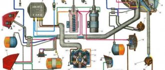
Electrical diagram
The electrical circuit of the YAVA 638 has been modernized based on the wiring of the previous model. The experimental 12-volt equipment was completely replaced and required the installation of a larger battery. Features of this innovation:
- the appearance of a 210-watt generator;
- possibility of installing an additional fog lamp;
- The stroller consumers were provided with current from a standard generator.
Thanks to the new system, the level of luminous flux was increased, which ensured driving safety at night. Spark formation has also improved, which contributes to more uniform and dynamic engine operation.
The new generator contains such basic elements as a rotor, stator and a metal casing. Its efficiency significantly exceeds the previously used 6-volt generator. This system allows charging even when the engine is running at low speeds.
However, the created system generated direct current, which needed to be converted into alternating current. For this purpose, a rectifier was built into the system. Its convenient location under the saddle makes it easy to carry out maintenance yourself.
However, when installing such equipment, the problem of overheating of the generator walls arose. It became impossible to use the rectifier inside a metal casing, so it was located under the driver's seat, providing air flow to cool the system.
The permissible power to a temperature of 150 degrees Celsius was 15 amperes. With the stroller and the use of all devices, it became possible to connect one additional consumer that does not require more than 40 watts of power.
Adjusting the gap between the contacts of the breaker and the ignition timing of the Java motorcycle
Setting the ignition timing is a very subtle and important adjustment.
The smooth and uninterrupted operation of the engine depends on the quality of this operation. Before you begin setting the ignition timing, it is advisable to make two devices that will greatly facilitate the upcoming work and increase its accuracy.
The first is a control light to determine when the breaker contacts begin to open. To do this, solder a crocodile-type contact and a connecting soft wire, also ending in a crocodile, to a regular 6 V, 1.5-5 W light bulb (see Fig. 35).
The second is an indicator for determining the ignition timing. A simple indicator can be made according to the drawing shown in Fig. 20; It is possible to make a more accurate device by adapting a dial indicator for this purpose.
Rice. 20. Indicator for setting ignition timing
Before starting the adjustment, it is necessary to inspect the breaker contacts, which must be in perfect condition and in full contact with each other. You cannot begin adjustment if the contacts are burnt or there are irregularities on their surfaces. Convexities on the contact planes must be eliminated. To do this, the breaker contacts must be removed and, carefully secured in a vice, the contact must be filed with a finely notched needle file in such a way as not to disturb the parallelism of the contact planes of the hammer and anvil contacts. Then it is recommended to polish the contact planes or at least sand them using fine-grained sandpaper. After finishing work, the breaker must be thoroughly cleaned of sawdust and washed in clean gasoline.
The plane of the newly filed contacts is checked by aligning them after installation in place. After making sure that the breaker contacts are in good condition and clean, you can proceed directly to setting the ignition timing itself.
The ignition timing of the Java-350 motorcycle must be adjusted in the following order.
1. Remove the spark plugs from both cylinders.
2. Remove the right crankcase cover.
3. Screw the indicator into the threaded hole of the spark plug in the right cylinder.
4. Set the piston of the right cylinder to top dead center (TDC) by turning the crankshaft with a wrench by the head of the bolt securing the generator rotor to the axle, or by rotating the rear wheel with direct transmission engaged.
5. In the position of the piston at i.d.t. set the gap between the contacts of the upper breaker (for the right cylinder) equal to 0.35-0.40 mm. To adjust the gap, it is necessary to loosen screw 8 (Fig. 27) securing the base of the anvil (fixed contact) and turn the base in the direction of increasing or decreasing the gap.
6. Having established the required gap between the contacts, turn the crank in the opposite direction and lower the piston 3.5-4.0 mm from the top. With this position of the piston and the ignition set correctly, the contacts of the breaker should begin to open and, accordingly, a spark should jump through the spark plug. It is most convenient to control the beginning of contact opening with a light bulb connected parallel to the breaker contact. When the ignition is turned on, at the moment the contacts begin to open, the light comes on, but when the contacts are closed, it does not light up.
To set the required contact opening moment, do the following:
a) loosen two screws 5 and 9 (Fig. 21) securing the main disk 7 to the body of the generator, and, turning clockwise or vice versa, install the disk so that the beginning of the opening of the breaker contacts coincides with the set position of the piston (3, 5-4.0 mm to b.m.t.); : the moment of the beginning of rupture is monitored by the flashing of the light bulb;
b) tighten screws 5 and 9 and again check the moment when the contacts begin to open; If necessary, if the adjustment is lost when tightening the screws, repeat the installation of the disk.
7. After setting the ignition timing for the right cylinder, set the ignition timing for the left cylinder. The sequence of operations and actions will be similar to those described above, but to adjust the moment when the contacts begin to open, you need to turn the base 2 of another breaker, attached to the main disk with two screws 1 and 4 (the main disk with the breaker for the right cylinder remains stationary). In no case is it permissible to adjust the gap between the contacts of the breaker after setting the ignition timing, since any change in the gap between the contacts significantly changes the amount of ignition timing.
Rice. 21. Motorcycle breaker "Java-350": 1 and 4 - screws securing the base of the left cylinder breaker; 2 – base of the left cylinder breaker; 3 — screw securing the base of the fixed contact of the left cylinder breaker; 5 and 9 - types of fastening of the main disk; 6 - protrusion; 7 - main disk; 8 — screw securing the base of the fixed contact of the right cylinder breaker.
Despite its apparent simplicity, ignition adjustment operations require certain skills. Complications may appear after final tightening of the screws securing the breakers to the base, especially if the screws were previously turned out significantly.
As the screws are tightened, the base of the breaker changes its position on the main disk (or the main disk changes position on the generator housing when adjusting the timing for the right cylinder). At the same time, the heel of the hammer changes its position in relation to the breaker cam; the gap between the contacts and the moment at which the contacts begin to ignite change accordingly. Therefore, when setting the ignition timing, it is necessary to take into account changes in the position of the chopper after tightening the screws and be able to make corrections to the measurements and to the position of the chopper before final tightening of the mounting screws.
Preventative maintenance of the ignition system. To ensure uninterrupted operation of the ignition system, the following rules should be followed.
1. Systematically clean the external ignition system devices from dust and dirt (ignition system devices must be spotlessly clean).
2. After 3000 km: a) lubricate with a drop of oil used for the gearbox, the fillets and the axles of the breaker hammers; b) check the condition and monitor the gaps between the contacts of the breaker and between the electrodes of the spark plugs; c) check the ignition installation and, if necessary, adjust it. To clean the breaker contacts during operation, use fine-grained sanding paper folded in half (Fig. 22).
Rice. 22. Cleaning the breaker contacts with sanding paper
This article is from the section - electrical equipment
, which is devoted to the topic of
adjusting the gap between the contacts of the breaker and the ignition timing of a Java motorcycle
. I hope you appreciate it!
Electronic ignition for Java 634
To page
1
, 2, 3. 21, 22, 23 Next
| Previous topic :: Next topic | |
| Author | Message |
| DooM Pros |
Registration: 04/05/2006 Messages: 258 Topics: 12 From: Azov, Rostov region Motorcycle: Java 638
And so today it happened! I installed and made the BSZ work at 6 volts. At the same time, I used a high-voltage coil from OKI 12 volts, a hall sensor, assembled a simple 6 volt transistor switch (in 20 minutes I had time to drink a beer) I used wires with a cross-section of 1.5 mm. Heads of wire from OKI. The modulator supplied a regular strip 11 mm wide. I installed all this miracle on IZHA Yu3. Everything worked perfectly! True, I was worried about how to properly connect the coil to the power supply, but I did (I had to drink another beer).
The result was a working 6-volt BSZ.
Pros: One coil left. No more fucking contacts. Starting the motorcycle has become much easier. It's much easier to set the ignition. I don’t see any downsides yet, I’ll do test drives tomorrow, I don’t really feel like it after the beer today. If anyone is interested, I can draw and post a diagram.
PS The idea may not be mine, but I brought it to life. _________________ It doesn't matter how it works, as long as it works..
Registration: 10/01/2005 Messages: 20 Topics: 4
Registration: 04/21/2005 Messages: 352 Topics: 16 From: Nizhnekamsk Motorcycle: Cz 455-05, Jawa 350-360-00, Sova 175
Registration: 04/05/2006 Messages: 258 Topics: 12 From: Azov, Rostov region Motorcycle: Java 638
Registration: 08/01/2005 Messages: 217 Topics: 3 From: Kurgan Moto: Java 350 634
Registration: 04/05/2006 Messages: 258 Topics: 12 From: Azov, Rostov region Motorcycle: Java 638
Registration: 09/17/2006 Messages: 470 Topics: 18 From: Tashkent Moto: kawasaki GPz400R
Registration: 09/17/2006 Messages: 470 Topics: 18 From: Tashkent Moto: kawasaki GPz400R
Well, what can you tell me? _________________ www.biker.uz
Registration: 04/05/2006 Messages: 258 Topics: 12 From: Azov, Rostov region Motorcycle: Java 638
Well, what can you tell me? Sorry, I don’t have any time right now, write to me on icq 236195646, we’ll figure it out there _________________ It doesn’t matter how it works, as long as it works..
Registration: 04/05/2006 Messages: 258 Topics: 12 From: Azov, Rostov region Motorcycle: Java 638
| This idea came to mind after I installed 638 BSZ with optics and FUOZ on Java. And I had Izhak for almost 3 years, lifeless. | ||
| to come back to the beginning | ||
| KDSUP Pioneer | ||
| Very interesting. Please write in more detail! I have Yavka-634 sitting idle here. The general from Izha wanted to install it, but he couldn’t get the faceplate. So for now I’ll do the BSZ on a 6-volt native generator. And then I’ll still set it to 12. What parts did you install? Everything in order, if possible | ||
| to come back to the beginning | ||
| Evgenn Cards: 3 Pros | ||
| Doom, yes. You must draw a diagram of the switch! | ||
| to come back to the beginning | ||
| DooM Pros | ||
| I made the switch according to this circuit (at the bottom of the article) https://twowheel.nm.ru/ignition.htm everything else is exactly the same as on a 12 volt BSZ tomorrow I’ll draw a circuit _________________ It doesn’t matter how it works, as long as it works.. | ||
| to come back to the beginning | ||
| Sergey (ASA) Experienced | ||
| I didn’t want to do it with a Hall sensor, maybe I could add an optocoupler? Waiting for the diagram _________________ JAWA 350 634.5 1981 | ||
| to come back to the beginning | ||
| DooM Pros | ||
| Sergey (ASA), you can use an optocoupler, it will be even better. For an optocoupler, the operating voltage from 5 volts is even better. _________________ It doesn't matter how it works, as long as it works.. | ||
| to come back to the beginning | ||
| Den Profi | ||
| Not long ago I bought a 634, 6 volt! Tell me everything from scratch where to connect and what to solder, diagrams and, if possible, photos, please. | ||
| to come back to the beginning | ||
| Den Profi | ||
| Dan wrote: | ||
| Not long ago I bought a 634, 6 volt! Tell me everything from scratch where to connect and what to solder, diagrams and, if possible, photos, please. | ||
| to come back to the beginning | ||
| DooM Pros | ||
| Dan wrote: | ||
| Dan wrote: | ||
| Not long ago I bought a 634, 6 volt! Tell me everything from scratch where to connect and what to solder, diagrams and, if possible, photos, please. | ||
| to come back to the beginning | ||
| DooM Pros | ||
| Here's a diagram. I took the switch from the Tambov bikers website: https://twolfs.narod.ru. In the diagram, the switch is surrounded by a frame. The breaker can be installed without additional modifications. The power of the resistors is: R1 and R5 – 0.5W, R2 and R3 – 2W, R4 – 5W, but can easily be reduced to R3 – 0.5W, R4 – 2W. The numbering of the transistor pins is given from the marking side. Transistors must be installed on the radiator. The size of the radiator can be small (the 30x50mm pin heats up only slightly). Because Since the heat sink of the transistors is connected to the collector (pin 2), it is impossible to place them on the same radiator without insulation! Mica spacers and dielectric washers are required to insulate the screws. The heatsink must be attached to the board with screws; it cannot hang only on the transistors (it will tear off)! Make the power paths (all to transistor VT2) as wide as possible on the board and cover them with a layer of solder to avoid burnouts. I assembled all the elements except the transistors on the legs of the same transistors, placed it on the radiator from the cooler under socket-A, installed the necessary gaskets, covered everything with thick wires and eventually filled the entire structure with a glue gun (molten polyethylene). This will save you from vibration and moisture. Place capacitor C2 as close as possible to the hall sensor; it serves to remove interference. The coil used is a regular one from OKI; during tests it “worked” at 5 volts. The only negative is a weak spark, but it is quite enough for stable operation. You should not leave the ignition on for a long time as the transistors and coil begin to overheat and may fail. Modulator strip 11 mm wide. The hall sensor was screwed directly to the generator through a thick gasket. This scheme was implemented on my Izh-Yu3. I did not carry out sea trials because there was a problem in the box. But the motorcycle started up better, kept stable idle, and revved up the gas quickly. | ||
| scheme_6v.jpg | ||
| Description: | ||
| this is a miracle |