Are you ready to take a risk?
In terms of complexity and abundance of systems, this carburetor can compete with the most sophisticated automobile ones (only those with electronic control are more complex). Hence the advice: if your experience with the motorcycle power system is limited to two or three successful repairs of devices like K-65, do not take risks - contact specialists. And second: work on a table covered with a sheet of clean white paper under the light of a bright lamp - this makes it easier to see the details and harder to lose them. And it is extremely difficult to examine the holes of the jets: they are so small that they can be clogged by the smallest speck of dust. Some channels are comparable in size to them. The outside of the carburetor must be clean before disassembling. The hands are the same as those of a surgeon before an operation. To work, you will need screwdrivers with unworn working surfaces. Most of the screws here are not only tightly tightened, but also secured with thread sealant, so that a screwdriver with a bad tip will only break their slots. Stock up on tweezers to make it easier to “catch” little things. Well, are you scared? If not, let's get started.
You can remove the carburetor through the hatch under the seat, but it will be easier if you first remove the entire trunk.
Removing the carburetor
You can get to it through a hatch in the trunk, under the saddle. But it’s easier to do this if you unscrew five bolts and dismantle the entire trunk along with the saddle, loosening the clamps. Loosen the one on the engine side more firmly so that the flange on the rubber pipe can come out of the deep groove on the carburetor outlet pipe. Usually, when the engine is not running, the gas valve with a pneumatic drive is securely closed, but it is better to be on the safe side - secure the end of the hose removed from the carburetor above the gas tank. Then disconnect the throttle cable and the connector of the wires A going to the carburetor starter. Clean the carburetor from dust with a soft brush, wash your hands and begin disassembling.
Float mechanism
Unscrew the three bolts and remove the float chamber cover. The float axis is held in place by a bolt. Unscrew it and remove the float block with the shut-off needle. The needle of this carburetor has a rubber conical part, and a spring-loaded rod rests against the float tongue. This design makes the unit sealed, very durable and resistant to abrasive wear.
Back view
: 1 — starting device; 2 - channel leading into the cavity under the spool membrane; 3 — air channel of the starting device; 4 — air jet of the main dosing system; 5 — accelerator pump nozzle; 6 - channel in which the air jet of the idle system is located; 7 - accelerator pump.
Possible malfunctions. The tide on the side walls of the floats should be parallel to the plane of the upper carburetor connector. If this is not the case, bend the metal tongue to achieve the correct position. Check it by placing the carburetor on its side - the tongue should just touch the needle rod, but not recess it.
Front view
: 1 - channel for the exit of the fuel-air mixture from the starting device; 2 — tube through which excess gasoline is drained if the float mechanism malfunctions; 3 - channel through which vacuum from the intake manifold is supplied to the idle air system shut-off mechanism.
Main dosing system
Its jet is located in the center of the float chamber. Through it, the fuel enters the emulsion tube, where it mixes with air and forms an emulsion. Air enters through a jet located at the carburetor inlet. The emulsion is dosed with a needle, which is fixed in the spool. A constant vacuum in the sprayer area is ensured by the spool. Next to the metering needle there is a hole through which the vacuum is transmitted to the cavity above the membrane, while the spring is compressed and the spool rises to the desired height.
Right view
: 1 — accelerator pump drive lever; 2 - throttle valve drive sector; 3 — screw for adjusting the amount of fuel-air mixture at idle.
To lean or enrich the combustible mixture, unscrew the screws securing the membrane cover and remove the spool with the membrane. Be very careful - the lid is made of fragile plastic. Remove the needle plug and the needle itself.
The range of adjustments is small - there are only three grooves on the needle; with the factory adjustment, the stopper is in the middle. During engine operation, spool oscillations occur due to air fluctuations in the intake tract. To prevent the stopper from breaking the needle groove, a rubber ring is installed under it. If you damage or lose it, you will not only shorten the service life of the unit, but also impoverish the mixture - the needle will drop lower without this part.
Left view
: 1 — idle quality adjustment screw; 2 — fuel inlet fitting; 3 - fitting through which you can drink fuel from the float chamber; 4 — screw-plug of the float chamber.
When you install the membrane in place, make sure that the protrusion on it fits into the recess on the body.
Possible malfunctions.
There may be two of them. The first is that the fuel nozzle is clogged. Blow it out. Second, the spool membrane is damaged. In this case, you cannot do without replacing the membrane with the spool.
Parts in the float chamber
: 1 — fuel tube of the starting device; 2 — block of floats; 3 - lock bolt; 4 — needle with a rubber tip and a spring-loaded rod; 5 - axis; 6 - tongue; 7 - main fuel jet..., 8 - ...and its emulsion tube; 9 — idle fuel jet.
Idle system
The idle speed (XX), as in most carburetors, is adjusted with two screws: mixture quality and quantity. The quality screw is located under the throttle valve axis on the left side of the carburetor, and the quantity screw is located on the axis sector stop. At the factory, quality adjustment is carried out as follows: the screw is tightened until it stops, and then unscrewed 2.5 turns. The XX system fuel nozzle is located next to the main fuel system nozzle; it and the emulsion tube form a single unit. The air jet is pressed into a tube-like boss to the right of the air jet of the main fuel system. The emulsion is supplied to three holes under the throttle valve. Why - by three? As the damper opens, its cut moves from one to the other, and they alternately find themselves in the zone of the highest air flow speed, and therefore in the zone of greatest vacuum. Thanks to this, the operation of the carburetor at the beginning of the throttle valve is improved and “dips” are eliminated.
When installing the spool, make sure that the protrusion on the diaphragm is in the recess of the housing (highlighted in red). The arrow indicates the hole through which additional air enters the idle system to turn it off.
When the damper is open to a large angle, the XX system is turned off by a special device. If the damper is closed, vacuum from the intake manifold enters the cavity above the device membrane and attracts it to the cover, compressing the spring. In this case, the XX system operates normally. When the throttle is open sufficiently, the vacuum in the manifold is too low to compress the spring, and it opens the valve with the diaphragm protrusion. Air from under the main fuel system valve diaphragm enters system XX. The vacuum in the XX system decreases - it becomes insufficient to supply gasoline. Possible malfunctions.
The XX system is one of the most vulnerable in any carburetor. First of all, due to the fact that the flow sections of the jets here are the smallest, which means they easily become clogged. If the diaphragm of the system that turns off XX becomes leaky due to age or for any other reason, the vacuum of the intake manifold will not be able to keep its valve closed, the fuel supply will be disrupted and the engine will stop running on XX. The same will happen if the valve loses its seal. The connector area between the membrane cover and the carburetor body (it contains the channel through which vacuum is supplied) is sealed with a rubber ring. The tightness of the seal will deteriorate - the operation of the membrane mechanism will be disrupted, and in addition, air will be sucked into the intake manifold, thereby making the mixture leaner. And it will become impossible to adjust the engine operation at XX.
Acceleration pump
When the throttle valve is opened sharply, the vacuum near the nozzle decreases, there is not enough of it to suck in a sufficient amount of gasoline - and a “failure” occurs in the engine’s operation. The purpose of the accelerator pump, as its name suggests, is to help the engine accelerate the scooter during this carburetor confusion.
Spool and related parts
: 1 — spool assembly with diaphragm; 2 — spool cover; 3 - screws; 4 — needle cover; 5 - spring; 6 - needle; 7 - rubber ring; 8 — needle stopper.
Its mechanism is located in the cover of the carburetor float chamber. When you open the throttle, its sector presses the lever. With his other shoulder he recesses the rod, at the opposite end of which there is a spring-loaded membrane. From the cavity under it, gasoline is supplied to a tube located in front of the spool, and, being ejected in a thin stream, enriches the mixture.
To prevent gasoline from coming back out of the tube when the membrane reverses, a ball valve is installed in its path. Under the pressure of the membrane, it opens, and when it returns back, it closes - and gasoline is sucked out of the float chamber through a very small hole in its cover.
Acceleration pump
: 1 - membrane; 2 — sealing ring of the inlet and outlet channels. The accelerator pump inlet port is highlighted in red. The accelerator pump check valve is shown with an arrow.
It is made much smaller than the hole in the ball valve plug. For what? The fact is that you only need to inject gasoline when you sharply open the throttle. In this design, gasoline has two paths: either through a small hole back into the float chamber, or, overcoming the force of the ball valve spring, into the carburetor diffuser. When the rod moves slowly, there is not enough pressure to open the valve, and gasoline has time to return to the chamber. But with fast, most of it ends up in the diffuser. Possible malfunctions.
Most often, the aged membrane fails. But the device can also be damaged due to excess zeal of the scooter owner. The inlet hole is very small and well “hidden” at the bottom of the float chamber. This is what this information is all about. Some scooter riders are accustomed to wiping off dirt with a rag, but for this carburetor such a method of cleaning is strictly contraindicated: you risk rubbing a speck or lint from a rag into the system. The result is clear - system failure.
Check valve device
: 1 - ball; 2 - spring; 3 - saddle.
Each time you turn the throttle of a scooter equipped with such a carburetor, you inject a portion of gasoline into the intake tract. And many onlookers strive to approach someone else’s equipment and twist the gas handle. Drive them away! Otherwise, they will “screw” so much fuel into the intake manifold that the engine will “flood” and you will not start it. It will work only after you unscrew and dry the spark plug and blow out the cylinder by turning the crankshaft with an electric starter.
Starting device
This system is fully automatic. Many people know how it works, so I won’t describe it again. I'll tell you about the location of the channels in the carburetor.
The air inlet is located to the left of the air jet of the main dosing system. The fuel jet is in the float chamber cover. The fuel flows through it into the well, and from there through a tube to the metering needle. Then the fuel-air emulsion is sent to the channel that leads it beyond the throttle valve.
Idle cut-off device parts
: 1 - spring; 2 - cover; 3 - membrane with a protrusion that opens the valve; 4 - valve; 5 - channel through which vacuum is supplied from the intake manifold; 6 - sealing ring.
Possible malfunctions.
If you have difficulty starting the engine, first check the resistance of the thermostat heater: it should be between 4 and 45 ohms. In our case it was 9.4 ohms. If the resistance is normal, remove the float chamber cover and introduce air into the tube through which fuel is supplied to the starter: it should flow easily. Then connect the heater to a 12V power source and after 5-7 minutes, feed air into the same tube again: no air should pass through.
Other “culprits” may be the fuel jet in the float chamber cover and a torn gasket sealing the joint of the float chamber cover in the well area. A faulty starting device or a torn gasket must be replaced, and the clogged nozzle must be blown out.
Starting device
: 1 - dosing needle; 2 - cylinder with a seal at the end; 3 - heater and thermostat in one housing; 4 - saddle; 5 — fastening of the starting device; 6 — fuel jet; 7 - fuel channel.
In order to disassemble the engine of a Chinese scooter, you don’t need to be a super mechanic or an overly gifted person. First of all, you need desire, accuracy and the availability of the necessary tools. Unfortunately, you can’t go anywhere without a good tool. Of course, there are people who repair scooters using a crowbar and a sledgehammer, but if you do it for yourself and for a long time, then you need to use only good tools. If you don’t have the tools, then it’s better to leave this idea.
Tools
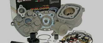
- Generator puller
- Variator puller (you can make it yourself)
- Kickstart sprocket puller (157QMJ engine only)
- Heads for 8, 10, 12, 17 mm
- Phillips and flathead screwdriver
- Small hammer
- Wish
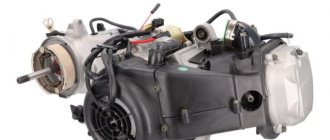
Most Chinese four-stroke scooter engines can be divided into two main types
- First type: 139QMB-series engine. This engine is very popular in the CIS countries and is installed on most Chinese four-stroke scooters
- Second type: 157QMJ-series engine. This engine has a larger volume than the first and, due to its higher price, is not so popular
Essentially, these two engines are a copy of the ancient Honda GY6 and differ from each other in displacement, kickstarter design, oil pump drive and electric starter drive. In all other respects, these engines are identical.
Typical 139QMB, in fact JL1P139QMB-2
And this is what a typical 157QMJ looks like, in fact LK162QMK
From a four-stroke internal combustion engine to a car
The team of engineers who worked on the creation of the unit included one talented guy - Gottlieb Daimler.
He was then passionate about the idea of creating a real car based on this engine. But Otto did not want to modernize an already successful engine. Daimler was forced to leave the project, but the desire to build a car did not go away.
As a result, together with his friend and like-minded person in 1889, Daimler assembled a car based on a four-stroke gasoline engine operating according to the Otto algorithm.
The first thing we will need to do:
- Remove the muffler
- Remove cooling shrouds
- Remove the generator
- Remove the variator
- Clean and blow out connectors
Removing the muffler is very easy and simple: unscrew the two nuts and two bolts on the cylinder head that secure the muffler to the frame (139QMB) or the rear wheel booster (157 QMJ)
Cooling shrouds are even easier to remove: unscrew all the bolts and screws that secure the shrouds to the engine and remove them.
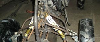
Removing the variator
Remove the variator cover. There is nothing complicated about this: we unscrew all visible bolts and remove the cover from the engine. On the 157QMJ engine, in order not to bend the kickstarter return spring bracket, first remove the crank, remove the retaining ring from the kickstarter shaft, and only then remove the cover itself. You can, in principle, remove it this way, but then you will have to trim the bracket a little.
Removing a variator is not much easier than removing a generator. As with a generator, you need a good puller. Fortunately, you can make a puller yourself: for a 139QMB engine, instead of a puller, you can use a metal plate: remove the bendix from the niche, insert the plate into it, press the variator impeller tooth against the plate and unscrew the nut.
You can also make a more advanced puller: look for an unnecessary clutch disc from an IZH motorcycle, weld a rod and several hooks for the impeller teeth to it
For the 157QMJ engine, the puller is made according to a slightly different principle
You can go to the nearest tool store and buy a universal key for the grinder. It is very suitable for removing the variator of the 157QMJ engine and costs a penny
The principle of removing the variator is identical to the principle of removing the generator: fix the impeller with a puller, unscrew the nut, remove the variator from the axle. After removal, we completely disassemble the variator and check all its parts for wear.
On the 157QMJ engine there is a kickstarter gear behind the CVT. It is not so easy to remove, but if you are going to subsequently halve the engine, you will have to remove it.
Troubleshooting
What to do if the hoverboard does not charge? Here are some simple tips for troubleshooting:
- First, disassemble the hoverboard.
To remove the bottom panel, use a screwdriver or screwdriver with the appropriate bit. This will allow you to get to the inside of the vehicle and try to find the problem of poor charging.
The side of the scooter with the charging port is the area you need to work on. Be careful during disassembly. Do not lose screws or washers, or use a drill to remove screws or bolts that will not come loose. There will be several wires directly on the inside of the plastic cover you just unscrewed.
They are responsible for charging the hoverboard: they connect the charger ports and the lithium-ion battery. The other wire line goes to the motherboard. You can temporarily disconnect it to avoid an unexpected power surge (only if the board is disconnected by a connector). If the wires are soldered, it is better not to touch them.
Is there blackening of the wire or oxidation of the contacts, is there a large amount of dust present? This may well be the reason for the device to not work correctly. Accumulations of dust must be removed, damaged wires must be replaced, and contacts must be cleaned to a metallic shine.
Having completed such an impromptu diagnosis, screw the cover back to the hoverboard, tightening all the removed bolts one by one.
They will help you make diagnostics more efficiently and without risk to the scooter. True, it is no longer free.
If, despite all this, your scooter continues to work incorrectly, you will need to contact the manufacturer and request repair instructions. In the worst case, the hoverboard will have to be sent back to the manufacturer under warranty. It may be that the device was initially faulty and will be replaced under warranty. It often happens that a newly purchased hoverboard does not charge.
Removing the piston
We clean and blow off the cylinder connectors, cylinder heads and valve covers. Unscrew the bolts on the valve cover and remove it from the head
Unscrew the nuts and bolts on the cylinder head
Remove the camshaft bed. The camshaft bed is practically not subject to wear. After removing it, just wash it and check for cracks.
We remove the chain from the camshaft and take it out of bed. The camshaft has two problematic points that are worth paying attention to: wear of the support bearings and the working surfaces of the cams
The cylinder, head and camshaft bed are centered relative to each other using guide bushings. These bushings tend to fall out of their sockets and then try to find it. To avoid this, immediately remove the bushings and put them somewhere away. Here and below, the bushings will be indicated by arrows.
Remove the cylinder head. The cylinder head is the most vulnerable part of the engine and the operating parameters of the engine directly depend on its condition. To avoid problems later: the head must be completely disassembled, inspected for cracks, the valve seats cut, new valves installed, the valves ground into the seats, new oil seals installed and the plane ground in on a plate or milled
Remove the cylinder. Immediately after removal, check the cylinder for liner wear and
We remove the retaining ring from the piston boss, push it out of the pin, and remove the piston. We check the piston for cracks and wear, paying special attention to the condition of the ring grooves and the rings themselves
Troubleshooting
The first and main sign that the equipment needs repair is the inability to start the engine. Scooter repair begins with identifying the fault and then eliminating it. In this case, the breakdown must be looked for starting from the place where the thermal energy of the burnt fuel is converted into mechanical energy of the rotating crankshaft of the engine. So let's get started:
— determine whether fuel enters the combustion chamber,
— is there a spark between the spark plug contacts?
If all of the above factors are present, then the following malfunctions are possible:
1. There was a breakdown of the spark plug insulator. To do this, simply replace the spark plug.
2. The ignition timing is off, and the fuel mixture does not ignite at the moment when the piston almost reaches its top dead center (TDC). Here you can no longer do without an indicator, with the help of which the position of the piston in the cylinder relative to TDC is determined, and at what moment a spark appears on the spark plug, igniting the fuel mixture. In this case, repairing the scooter will consist of setting the correct ignition timing recommended for this type of engine.
If there is no spark at the spark plug, then the following problems may occur:
1. The spark plug is faulty.
2. The candle holder is faulty.
3. The armored wire is broken.
4. The ignition coil has burned out.
5. If the ignition is electronic, then either the ignition unit or only the Hall sensor may be damaged.
If the fuel mixture does not enter the combustion chamber, this may be caused by such problems.
If the scooter is two-stroke:
1. fuel filter clogged;
2. The carburetor is clogged or broken.
If it is a four-stroke engine, then a malfunction of the gas distribution system (burnouts or bent valves) may be added to the breakdowns.
Disassembling the crankcase: removing the crankshaft, timing chain
We unscrew the bolts on the cover (139QMB fewer bolts: 8), lightly tap it with a mallet and remove it from the engine. The crankcase guide bushings, as in the case of the cylinder head, will be marked with arrows. Covers especially on 139QMB engines. When you remove the cover, carefully inspect its body and if the cracks are not significant,
157 QMJ looks more complex inside
To disassemble 157QMJ you need to do the following:
- Remove the starter idler gear
- Unscrew the nut on the freewheel
- Remove the chain from the oil pump
- Unscrew the last bolt securing the engine crankcase
With 139QMB there is much less fuss:
- Remove the oil pump gear
- Unscrew the last crankcase tightening bolt
Take an old blunt screwdriver and use a hammer to unscrew the overrunning clutch nut (the thread is left-handed: unscrew strictly clockwise!)
One of the most important parts of any scooter is the carburetor; it is responsible for the correct supply of fuel, and therefore you should have a properly configured carburetor. Initially, the manufacturer makes scooters that would be suitable for a certain climatic situation, and the fuel system may not be able to cope with our weather changes, as a result of which the carburetor does not work correctly and most often does not maintain speed. That is why modern scooters are equipped with various adjusting bolts so that the vehicle owner can adjust the engine to the desired parameters, and adjusting the scooter’s carburetor does not cause difficulties.
A carburetor is a specific part of a scooter that is responsible for preparing the fuel mixture, mixing gasoline with air. The standard ratio of gasoline to air is 1 to 15, so any carburetor should produce these figures. Also, depending on this ratio, the mixture may be different; in the above parameters it will be optimal. But if you want to get a mixture that does not stall the engine at idle, use a ratio of 1 to 13.
After this, you can call the mixture “rich.” And finally, the last type is a lean mixture. This is the worst option, where the ratio of fuel to air is 1 to 17. With a lean mixture, there is a risk of carbon formation in the piston and its complete breakdown, so next we will talk about how the carburetor is adjusted on a 4t scooter.
Do-it-yourself wheel studding.
Good day everyone!
This article is from the category “It was evening, there was nothing to do.” This is not an instruction manual, it is just a description of my studding process. I haven’t discovered America, but maybe someone will find it useful. I’ll try to explain everything in an accessible way. Lyrical digression
Recently my wife and I moved to my mother-in-law, and now I live in a remote village. The nearest city, where there are glimpses of civilization, is about 20 kilometers away. Of these, 5 kilometers are off-road, where the wheels of snow removal equipment have never driven, the remaining 15 are just snow rolled by cars. For personal transport, I have a mountain bike and a scooter. No, a bicycle is, of course, good, but it’s slow, and the load capacity of a scooter is better.
As always, winter suddenly came, and the question became acute: how to get to the city? After the first attempt to ride in snowy weather on ice, thoughts about preparing the scooter for winter appeared in my head. It was decided to install studded tires. Because Factory tires are expensive, so I started googling how to make studs with my own hands. Unfortunately, this issue is poorly covered on the Internet. On one forum I came across instructions from Evgeny Matveev. TYTS
In principle, from what I read, almost everything becomes clear, the only thing that is not clear is what the length of the screws and the diameter of the washers should be. And it’s not clear how much there should be, and how much all this fun will cost. I have experimentally determined that the optimal length of screws for me is 16 millimeters (5x16), although it’s probably possible to take it shorter. And the washers needed are 5x15. I didn’t have spare tires, so I went to a scooter workshop, where they kindly gave me two dead tires. They gave us different tires, one a little larger. But, as they say, “Don’t look under the tail of a gift horse.” Having marked the tenon markings with a pencil, I counted 100-150 screws per wheel. I decided to take with a reserve (in case my imagination runs wild), and took only 350 pieces. All this cost 95 UAH (about $11.5).
The tenon took 225 screws. 75 for the front, and 150 for the rear wheel. One tire was softer, so I had to put washers on the inside to prevent the screw heads from falling through. I have cameras in my wheels. To prevent them from rubbing against the heads of the screws, I made gaskets from old inner tubes around the entire circumference of the wheel. Perhaps it will also hold air on tubeless cameras, because... everything is held together very tightly. I note that the most convenient way is to tighten all the nuts and tighten everything with a screwdriver with the appropriate attachment. The spikes protrude by 10-11mm. There are 6-8 studs per contact patch.
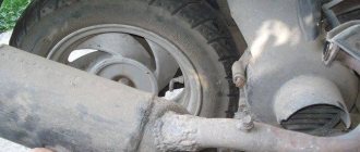
Studded tires side view
I immediately carried out a test run, the result exceeded all expectations! The scooter handles very confidently on snow and sometimes drifts a little on ice. It also drives fine on asphalt. You can drive on a flat surface at speed without fear of falling. The wheels do not slip, the spikes cling tightly. The brakes work very well. Since I put wide tires on the front, the spikes caught the beak a little when driving, so I had to shorten them a little. If you drive on asphalt, the spikes may wear off quickly.
PS.PS: On video
test drive immediately after studding. I drove slowly, because... I’m not used to it yet, and the thorns caught the beak. Now I drive faster and more confidently.
The hand is FAIL
Adjusting the carburetor of a 4-stroke scooter
In general, the number of strokes in a scooter does not play such an important role when adjusting, because the jets are almost the same everywhere (fuel and idle), so the process occurs according to the individual indicators of the scooter.
Important
: Adjustment of the carburetor of a 4t 80cc scooter or other volume is carried out only on a warm engine. It is also important to consider that before adjusting, the carburetor must be disassembled and cleaned of dirt.
Setting up the carburetor includes several manipulations:
- Fuel level adjustment;
- Idle speed adjustment;
- Adjusting the quality of the mixture using a jet;
- Adjusting the quality of the mixture by setting the needle position.
Let's start with the simplest action - adjusting the idle speed.
Adjusting the idle speed on a scooter
After the engine is warmed up, you can adjust the idle speed, this is done using a special screw located on any carburetor. The idle speed is adjusted to ensure that the scooter operates correctly and smoothly when not in use. The location of the screw may vary depending on the scooter model. For example, the screw is located in the center, and the mixture quality screw is installed on the left side.
The adjustment process is quite simple, as soon as the scooter starts, rotate the screw, where when tightened the speed will increase, opening the jet reduces the speed. Again, adjustments are made only on a well-warmed engine.
Setting the fuel level
This procedure is also carried out using a jet located at the very bottom of the float chamber. The first step is to unscrew this screw, but gasoline should not come out of the tube. The tube is located below the jet and is usually transparent. It shows the fuel level, so lift it in a vertical position. If the fuel level in the float chamber is normal, the gasoline in the tube will be slightly less than the cap curb.
Important
: You need to check this indicator only with a warm running engine.
Adjusting the fuel level in the carburetor of a 4t scooter is as follows: remove the float chamber and find the needle inside. The needle has marks and a small locking ring. You can increase the fuel level by installing the ring above this indicator, and decrease it by doing the opposite.
Adjusting the mixture quality on a scooter
We indicated above that the mixture can be optimal, rich or lean. So, manufacturers of a certain scooter model recommend using specified proportions, which means that sooner or later you will have to make adjustments. Most 4t scooters have an adjustment screw, otherwise the procedure is done using a needle in the throttle. The mixture is enriched by turning the screw clockwise; when the screw is turned counterclockwise, the mixture becomes lean. Adjusting the indicator on scooters without a mixture quality screw occurs by increasing or decreasing the height of the needle.
Troubleshooting
Malfunctions of electrical equipment and fuel systems are the most regular of all problems that arise among scooter owners.
It often happens that a breakdown suddenly occurs to the scooter. Repairing the carburetor, as a rule, allows you to resume the functioning of your “faithful horse”.
Usually, to do this, it is enough to remove the carburetor, clean the dust from the outside and the tarry deposits of gasoline and other debris inside. Clean and blow out the air and fuel channels and jets, check the condition of the fuel needle and throttle valve, and then reassemble and adjust it.
Fixing more complex breakdowns at home is not always possible, since specific tools are often required that are not widely available.
Thus, for a technically literate person, repairing a scooter with your own hands will not be very difficult if you have minimal knowledge and skills in handling equipment, as well as the necessary tools.
How do you know if the mixture is rich or lean?
To find out this indicator, you should look at the condition of the spark plug, namely at its electrodes. When the mixture is lean, the electrodes are quite white and traces of melting are visible; when the mixture is rich, the electrodes are too black and strong carbon deposits are visible. Of course, the optimal mixture is characterized by the normal state of the candle.
It might be useful to read:
- Ethiopia: the country and its description;
- Solaris maintenance;
- The car shakes and the ESP light is on. The ESP on a Volkswagen is on;
- Galvanizing the body: which cars are better protected from corrosion;
- Which gear oil is better to use: test results and reviews Oil for the VAZ 2110 gearbox recommended by the manufacturer;
- At what age can you ride in the front seat?
- Particulate filter: why is it needed on a car? ;
- Weaknesses and disadvantages of the Nissan Note Driving characteristics of the Nissan Note;